
EX78934E-0VB - Network Card/Adapter EtherWAN - Free user manual and instructions
Find the device manual for free EX78934E-0VB EtherWAN in PDF.


| Product Type | Network Adapter / Interface Card |
| Brand | EtherWAN |
| Model | EX78934E-0VB |
| Dimensions (approx.) | 120 x 80 x 20 mm |
| Weight (approx.) | 150 g |
| Power Supply | Power over Ethernet (PoE) or external 12V DC adapter |
| Network Interface | 1x 10/100/1000Base-T RJ45, 1x SFP slot |
| Compliance | IEEE 802.3, IEEE 802.3u, IEEE 802.3ab, IEEE 802.3z |
| Operating Temperature | -40°C to 75°C |
| Main Functions | Ethernet data transmission, network bridging, media conversion |
| LED Indicators | Power, Link/Activity per port |
| Mounting | DIN rail or wall mount |
| Cleaning and Care | Wipe with a dry, lint-free cloth; avoid liquids |
| Safety Precautions | Disconnect power before cleaning; use only supplied power adapter |
| Spare Parts and Repairability | No user-serviceable parts; contact EtherWAN support |
| General Information | Industrial-grade network adapter for harsh environments |
Frequently Asked Questions - EX78934E-0VB EtherWAN
User questions about EX78934E-0VB EtherWAN
0 question about this device. Answer the ones you know or ask your own.
Ask a new question about this device
Download the instructions for your Network Card/Adapter in PDF format for free! Find your manual EX78934E-0VB - EtherWAN and take your electronic device back in hand. On this page are published all the documents necessary for the use of your device. EX78934E-0VB by EtherWAN.
USER MANUAL EX78934E-0VB EtherWAN
natural_image
Abstract blue brushstroke design resembling a stylized letter or symbol (no text or symbols present)EtherWAN
natural_image
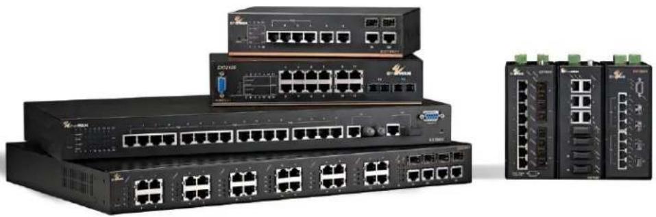
Exterior view of multiple network switches and networking equipment (no visible text or labels)Hardened Managed Ethernet Switch Firmware 4.02
User's Guide
FastFind Links
Computer Setup
Setting the initial IP address
All Rights Reserved
Dissemination or reproduction of this document, or its contents, is not authorized except where expressly permitted. Violators are liable for damages. All rights reserved, for the purposes of patent application or trademark registration.
Disclaimer of Liability
The information contained in this document is subject to change without notice. EtherWAN is not liable for any errors or omissions contained herein or for resulting damage in connection with the information provided in this manual.
Registered Trademarks
The following words and phrases are registered Trademarks of EtherWAN Systems Inc. EtherWAN
All other Trademarks are property of their respective owners.
Warranty
For details on the EtherWAN warranty replacement policy, please visit our web site at: www.etherwan.com
Products Supported by this Manual:
EtherWAN switches running firmware version 4.02:
EX61000 / EX63000 / EX71000 / EX73000 / EX78000 / EX87000 / EX77000 / EX27000
Contact EtherWAN Systems
Corporate Headquarters
EtherWAN Systems Inc.
2301 E Winston Rd Anaheim
Anaheim, CA 92806
Tel: (714) 779 3800
Fax: (714) 779 3806
E-mail: support@etherwan.com
Table of Contents
Preface....xiv
Applicable Models....xiv
Release Notes for Firmware 4.02 xiv
Safety and Warnings ...... xvi
Typographic Conventions ...... xvi
Computer Setup.... 17
Management Methods and Protocols ...... 17
Default IP....18
Login Process and Default Credentials....18
Setting the initial IP address.... 19
Simple IP Addressing ....19
CLI Command Usage.... 20
Navigating the CLI Hierarchy....20
CLI Keyboard Shortcuts....21
CLI Command modes....21
Global Configuration Mode 21
MSTP Configuration Mode....21
Interface Configuration Mode....22
VLAN Database Configuration Mode 22
Saving a Configuration from the CLI 23
System Menu (web interface) 23
System Information....23
System Name/Password....24
System Name/Password using the CLI....26
Show Switch Model using the CLI....27
Configure the Reset Button....27
IP Address....28
DHCP Client 29
DHCPv6....29
Default Gateway 29
iii
DNS Server....30
IP Address - Configuration using the CLI 32
IP Address 32
Default Gateway 33
Domain Name Server (DNS)....33
Enable/Disable DHCP Client on a VLAN....34
Enable/Disable Static IP on a VLAN....35
Set the IPv6 Address of an Interface....35
Set the IPv6 Address through DHCP 36
Enable/Disable DHCP Server for IPv6 36
Configure DHCPv6 server settings ....37
Management Interface....37
HTTPS....37
Telnet....38
SSH (Secure Shell)....38
Management Interface Configuration using the CLI 39
Enabling/Disabling Telnet 39
Enabling/Disabling SSH....40
Enabling/Disabling HTTP and/or HTTPS 41
Save Configuration Page....42
Save Configuration 43
Load Configuration....43
Backup Configuration....43
Restore Default....43
Auto Save 44
Saving and Loading Configurations Using EB-232....44
Configure Reset Button....46
Show Running Configuration using the CLI....47
Show Configuration....47
Control Access to show running-config 47
Save Configuration Page using the CLI 47
Saving a Configuration....47
Restore Default Settings....48
Load Configuration from a TFTP Server 48
Save Configuration to a TFTP Server 48
Auto Save Configuration....49
Firmware Upgrade....49
Firmware Update using the CLI 50
Reboot....51
Reboot using the CLI 51
Logout 51
Logout from the CLI....51
User Account Page....52
Changing the User Mode 52
Creating a New User....53
Changing an Existing User Account....53
User Privilege Configuration ....54
User Account Settings using the CLI....57
Multi-User Mode....57
Single User Mode ....57
Radius User Mode....58
Tacacs User Mode....58
Creating a New User....59
Permissions 59
Diagnostics 60
Utilization....60
System Log....60
System log using CLI commands....62
Remote Logging 64
Remote Logging using CLI commands....66
ARP Table....67
ARP Table using CLI Commands 68
Route Table....68
Route Table Using CLI Commands 69
Alarm Setting....69
Alarm Setting Using CLI Commands 70
Set Normal State for Alarm Relay....71
Configuring Email Alarm Notifications....72
Email Alarm Notifications Using CLI Commands 73
Port 74
Configuration....74
Port Status....76
Rate Control....77
RMON Statistics 78
Per Port VLAN Activities 79
Port Security 80
Port Configuration Examples Using CLI Commands....83
Setting the Port Description 83
Enable or Disable a Port 84
Setting the Port Speed....84
Setting Port Duplex....85
Enable or Disable Port Flow Control 85
Display Port Status 85
Setting a Port's Rate Control....86
Display a Port's RMON Statistics....86
Display a Port's VLAN Activities....86
Disable Port on Link Down....86
Enable MAC port security 87
Disable MAC port security....87
Assign MAC Addresses for Port Security 87
Delete MAC Address for Port....88
Set Port Security to Sticky Mode....88
Disable Sticky Mode 89
Display Port Security MAC Addresses 89
Switching....90
Bridging 90
Aging Time....91
Threshold Level 91
Storm Control Type....91
Loopback Detect....92
Loopback Detection (Global)....93
Loopback Detect Action 93
Loopback Detect Recovery Time....93
Polling Interval 93
Loopback Detection (Per Port)....94
Storm Detect....95
Enable/Disable Storm Detection 95
Static MAC Entry 96
Adding a Static MAC Address to a Port....97
Removing a Static MAC Address from a Port....97
Adding a MAC to the Static-MAC-Entry Discard Table....98
Removing a MAC address from the Static-MAC-Entry Discard Table .....98
Port Mirroring....99
Link State Tracking....101
Enable/Disable Link State Tracking ....101
Port Settings....101
PoE (Power over Ethernet) - System and Port Settings....102
PoE System Setting....102
PoE Port Setting 103
PoE Scheduling....105
PoE Watchdog....106
Switch Configuration Examples Using CLI Commands....108
Setting the Aging Time Value....108
Enabling Port Isolation....108
Setting Storm Control....109
Enabling Loopback Detect (Global)....109
Setting the Loopback Detect Action 109
Setting the Loopback Detect Recovery Time ....110
Setting the Loopback Detect Polling Interval....110
Enabling Loopback Detect (Port) 110
Configuring Storm-Detect....111
Adding a MAC Address for Static-MAC-Entry Forwarding....114
Discard a Static MAC Entry....115
Configuring Port Mirroring....115
Enabling a Link State Tracking Group....116
Assigning a Port to a Link State Tracking Group....116
Setting PoE Power Budget....116
PoE Port Settings....117
PoE Scheduling 120
PoE Watchdog....122
Extend PoE to 250 Meters ....123
Trunking 123
Overview 123
Static Channel Trunking....124
Link Aggregation Control Protocol....124
Port Trunking....125
LACP Trunking 127
Trunking Configuration Examples Using CLI Commands....131
Adding an Interface to a Static Trunk....131
Adding an Interface to a LACP Trunk....131
Setting the LACP Port Priority....132
Setting the LACP Timeout....132
STP/Ring Page – Overview 133
Choosing the Spanning Tree Protocols....133
Spanning Tree Protocol (STP) 133
Rapid Spanning Tree protocol (RSTP)....133
Multiple Spanning Tree Protocol (MSTP)....133
STP/Ring Page - Configuring RSTP 134
Global Configuration Page....134
Enabling the RSTP Protocol ....134
Additional Global Configuration page settings....134
The Root Bridge & Backup Root Bridge 136
Setting the MAX Age, Forward Delay and Hello Timer....137
RSTP Port Setting Page 138
Spanning Tree Port Roles....138
Path Cost & Port Priority 139
Point to Point Link....141
Edge Port....142
RSTP Configuration Examples Using CLI Commands....142
Enabling the Spanning Tree Protocol....142
Bridge Priority, Max Age, Forward Delay, and Hello Time....142
Modifying the Port Priority and Path Cost....143
Manually Setting a Port to be a Shared or Point to Point Link 143
Enabling/Disabling a port to be an Edge Port....144
STP/Ring Page - Configuring MSTP 145
Global Configuration Page....145
Enabling the MSTP Protocol....145
The CIST Root Bridge & Backup CIST Root Bridge 146
Setting Bridge Priority 147
Configuring the CST Network Diameter 148
MSTP Properties Page 149
Configuring an MSTP Region....149
Configuring the IST Network Diameter....150
MSTP Instance Setting Page....151
Setting an MSTP Instance ....151
Modifying MSTP parameters for load balancing....153
MSTP Port Setting page 155
Adjusting the blocking port in a MSTP network....155
MSTI Instance Port Membership....156
MSTP Configuration Examples Using CLI Commands ....157
Enabling Spanning Tree for MSTP....157
Bridge Priority, Max Age, Forward Delay, and Hello Time....158
IST MAX Hops....158
MSTP Regional Configuration Name and the Revision Level....159
Creating an MSTI Instance ....159
Setting MSTI Priority....160
Modifying CIST Port Priority and Port Path Cost....160
viii
Adding a Port to an MSTI Instance 161
STP/Ring Page - Alpha Ring 162
Alpha Ring Setting Page....162
EtherWAN Alpha-Ring Technology 162
Implementing a Simple Alpha-Ring 162
Alpha-Ring V2....163
Connecting two Alpha-Ring Networks together (Ring Coupling)....164
Connecting Additional Rings (Redundancy Pairs)....165
Configuring Alpha Ring using CLI commands....168
Enable Alpha Ring and Alpha Ring V2 Protocols....168
Set the Ring Ports....169
Show Ring, Port and All States....169
Define a Ring's Blocked Port 170
Set Delay Time for Restoration of a Failed Port 170
Enable Ring Coupling 170
Set Ring Coupling Ports....171
Enable Redundancy Pairs....171
Configure Redundancy Pairs ....171
Show Ring Coupling, Port Coupling, and Redundancy Pair States ....172
STP/Ring Page – Alpha Chain 173
The Alpha Chain Protocol....173
General Overview....173
Alpha Chain Settings 173
Global Settings 174
Configuring the Alpha Chain Ports 175
Alpha Chain Pass-Through Ports....176
Configuring Alpha Chain using CLI commands....177
Storm Control....177
Configuring Chain Ports....177
Configuring Chain Pass-Through Ports....178
STP/Ring Page - Advanced Setting.... 179
Advanced Bridge Configuration 179
Advanced Per Port Configuration....180
Configuring Spanning Tree Advanced Settings using CLI commands....182
Enabling BPDU Guard Globally 182
Enabling BPDU Guard on a Port....182
Enabling BPDU Guard Error Disable-timeout....183
VLAN....184
Port Based VLAN vs. Tagged Based VLAN....184
Configuring VLANs in Port Based VLAN Mode....184
Enabling Port Based VLAN 184
Port Based VLAN Configuration Examples ....185
Port Based VLAN Configuration Examples using CLI Commands ....187
VLAN Configuration in 802.1Q Tag Based VLAN Mode....188
General Overview 188
Enabling 802.1Q Tagged Based VLAN....189
Configuring 802.1Q VLAN Database....190
802.1Q Tag Based VLAN Configuration Examples Using CLI Commands .....191
Configuring a 802.1Q VLAN....191
Configuring an IP Address for a Management VLAN 192
Removing an IP Address from a Management VLAN....192
Configuring an Access Port....192
Configuring a Trunk Port....193
Add an IP to the Management VLAN 194
Configuring the Port Type and the PVID setting....195
Configuring the VLAN Egress (outgoing) Member Ports ....195
QoS 198
Global Configuration Page....199
Web GUI Interface 199
QoS Global Configuration using the CLI Interface ....201
Enable/Disable QoS Trust....201
Configuring the Egress Expedite Queue 202
802.1p Priority Page 203
Web GUI Interface 203
802.1p Priority Submenu – CLI Interface 204
DSCP Page – HTTP Interface ......205
DSCP Submenu – CLI Interface 206
QoS Interface Commands – CLI Interface 206
ACL (Access Control List) 207
General Overview....207
Configuring ACL....208
ACL Policy Map....209
IP Access List 211
IP Access List (Extended)....212
Mac Access List....214
Layer 4....216
x
Bandwidth Limiting....217
Applying a Policy Map to a Port 219
Modifying/Adding an Existing Policy Map....219
Adding a New ACL Class to an Existing Policy Map 220
Adding an Existing ACL Class to an Existing Policy Map 221
Removing an ACL Class....223
ACL Configuration Examples Using CLI Commands 227
Enabling QoS....227
Creating a Standard IP Access List....227
Creating an Extended IP Access List 228
Creating a MAC Access List ....228
Creating an ACL Class Map with Layer 4 Access List....229
Creating a ACL Class Map with an IP or MAC Access List ....230
Creating an ACL Policy Map....231
Appling an Existing ACL Policy to a Port....232
Deleting an ACL Class....232
Deleting an ACL Policy ....233
SNMP 234
SNMP General Settings....234
Configuring SNMP v1 & v2 Community Groups....238
Configuring SNMP v3 Users....240
Adding SNMP v3 Users to the switch....240
Deleting SNMP v3 Users from the switch....243
SNMP Configuration Examples Using CLI Commands....244
Enabling SNMP and configuring general settings....244
Configuring SNMP Traps ......245
Configuring SNMP v1 & v2 Community Groups 246
Adding SNMP v3 Users ....247
AAA/802.1x (Authentication, authorization, and accounting).... 247
Configuring Radius from the GUI....248
Enabling Radius....248
Adding a Radius Server 249
Enabling 802.1X on a Port ....250
Configuring TACACS+ from the GUI....251
Enabling TACACS+ 251
Adding a TACACS+ Server....252
AAA/802.1x Configuration Using the CLI 253
View RADIUS Status 253
Enable RADIUS Globally 253
Configure RADIUS on Ports....254
Configure MAC-Based Authentication....254
TACACS+ Authentication and Authorization 255
Configure TACACS+ Server 255
LLDP 255
LLDP General Settings....256
Enable/Disable LLDP 256
Holdtime Multiplier 256
Global TLV Setting....257
LLDP Ports Settings 258
Enabling LLDP transmission for a specific Port....258
Enabling LLDP Reception for a specific Port....259
Enabling Notifications 259
LLDP Neighbors 261
LLDP Statistics 262
LLDP MED Network Policy 262
LLDP MED Location ID....264
LLDP MED Port Settings 266
LLDP Configuration Examples Using CLI Commands 268
Enable/Disable LLDP 268
LLDP Holdtime Multiplier....268
LLDP Transmit Interval 269
Enable/Disable Global LLDP TLVs 269
Enabling LLDP Transmit on a Port....270
Enabling LLDP Receive on a Port....270
Enabling LLDP Notify....271
Enabling Transmission of the Management IP 271
Enabling Specific TLV's on a Port 272
Enabling LLDP MED TLV's on a Port 272
Set LLDP-MED location information....273
Other Protocols.... 274
GVRP 274
General Overview 274
Enabling the GVRP Protocol at the Global Level 275
Enabling the GVRP Protocol at the Port Level 276
GVRP Configuration Examples Using CLI Commands 278
IGMP Snooping 281
General Overview 281
Enabling the IGMP Snooping Modes 282
Configuring IGMP Snooping General properties 282
Configuring IGMP Passive Mode Specific properties 283
Configuring IGMP Querier Mode Specific properties....285
Configuring IGMP Unknown Multicast Forwarding 286
Monitoring Registered Multicast Groups 290
IGMP Configuration Examples Using CLI Commands 291
Network Time Protocol (NTP) 298
Setting RTC Time 299
Enabling NTP....299
Setting the NTP Server IP Address....299
Setting the Time Zone....299
Setting the Polling Period....300
Manually Syncing Time....300
Daylight Savings Time - Weekday Mode....300
Daylight Savings Time – Date Mode 301
Network Time Protocol Configuration Examples Using CLI Commands....302
GMRP....305
General Overview 305
GMRP Normal mode....306
GMRP Fixed mode ....306
GMRP Forbidden mode....306
GMRP Forward All mode 306
GMRP Disabled mode 306
Enabling the GMRP Feature Globally on the Switch 307
Configuring the GMRP Feature Per Port....307
GMRP Configuration Examples Using CLI Commands....309
DHCP Server....311
General Overview 311
Configuring the DHCP Server ....312
DHCP Configuration Examples Using CLI Commands ....314
DHCP Relay 316
General Overview 316
Configuring the DHCP Relay ....316
DHCP Relay Configuration Examples Using CLI Commands....317
Contact Information 320
PREFACE
Audience
This guide is designed for the person who installs, configures, deploys, and maintains the Ethernet network. This document assumes the reader has moderate hardware, computer, and Internet skills.
Document Revision Level
This section provides a history of the revision changes to this document.
| Revision | Document Version | Date | Description |
| A | Version 1 | 08/08/2019 | Initial release for Firmware version 4.02 |
| A | 2 | 12/04/2019 | Added Applicable models EX87000, EX77000, and EX27000 |
| A | 3 | 12/19/2019 | Modified port truking information |
| A | 4 | 02/25/2020 | Fixed many incorrect field data errors |
| A | 5 | 09/24/2020 | Added info about PoE extend mode |
| B | 1 | 08/27/2021 | Added Port Security configuration info |
| B | 2 | 12/16/2021 | Firmware 4.02.4.3. Support SFTP firmware/configuration upgrade feature, added multi-VLAN support for Port Security |
Applicable Models
EtherWAN switches running firmware version 4.02.4.3:
EX27000 / EX61000 / EX63000 / EX71000 / EX73000 / EX77000 / EX78000 / EX87000
Release Notes for Firmware 4.02
NEW FEATURES
- Supports AES encryption standard for SNMPv3, including support for AES-128, AES-192, and AES-256.
- Add neighbor only option.
- Support for password complexity and set maximum number of failed logins
- Log can be saved to flash
-
Email alarm notifications – New feature allows switch to send email alerts to up to three recipients when an environmental alarm is triggered, configurable from GUI and CLI.
-
LinkDown Disable – As a security feature, a port can be configured to automatically shut down when it becomes disconnected. When this feature takes effect, the port must be re-enabled manually.
- Control Access to show running-config
- Multiple (up to 2) NTP servers can be configured
- Show system uptime in CLI
- EX78000 only: PoE can be extended to 250m with 10Mbps transfer speed. When the extend mode is enabled, single POE port supports 250m transmission distances and 10Mbps speed. New CLI Commands: poe extend-mode enable
Changed
Loopback detect MAC address changed from 01-80-C2-00-00-05 to 01-80-C2-00-03-00.
Note: It is suggested to pre-test the PoE Extend Mode function before deployment. The maximum available transmission distance of PoE depends on the negotiation result of PD and PSE. Some PDs using EtherWAN PoE/PSE switches may only support a standard distance of 100 meters. Contact EtherWAN if assistance is needed.
Firmware 4.02.3.2
- Static and dynamic (sticky) port security feature added.
Document Conventions
This guide uses the following conventions to draw your attention to certain information.
Safety and Warnings
This guide uses the following symbols to draw your attention to certain information.
| Symbol | Meaning | Description |
 | Note | Notes emphasize or supplement important points of the main text. |
 | Tip | Tips provide helpful information, guidelines, or suggestions for performing tasks more effectively. |
 | Warning | Warnings indicate that failure to take a specified action could result in damage to the device, or could result in serious bodily injury. |
 | Electric Shock Hazard | This symbol warns users of electric shock hazard. Failure to take appropriate precautions such as not opening or touching hazardous areas of the equipment could result in injury or death. |
Typographic Conventions
This guide also uses the following typographic conventions.
| Convention | Description |
| Bold | Indicates text on a window, other than the window title, including menus, menu options, buttons, fields, and labels. |
| Italic | Indicates a variable, which is a placeholder for actual text provided by the user or system. Angled brackets (<>) are also used to indicate variables. |
| screen/code | Indicates text that is displayed on screen or entered by the user. |
| <>angled brackets | Indicates a variable, which is a placeholder for actual text provided by the user or system. Italic font is also used to indicate variables. |
| [] square brackets | Indicates optional values. |
| {} braces | Indicates required or expected values. |
| | vertical bar | Indicates that you have a choice between two or more options or arguments. |
COMPUTER SETUP
The end user's management computer may need to be reconfigured prior to connecting to the switch in order to access the switch's web interface through its default IP address (See Default IP).
Management Methods and Protocols
There are several methods that can be used to manage the switch. This manual will show the details of configuring the switch using a web browser. Each section will be followed by the CLI (Command Line Interface) commands needed to achieve the same results as described in that section.
The methods available to manage the EtherWAN Managed Switch include:
- SSH - Secure Shell CLI that is accessible over TCP/IP networks which and is generally regarded as the most secure method of remotely accessing a device.
- Telnet - is like SSH in that it allows a CLI to be established across a TCP/IP network, but it does not encrypt the data stream. This type of connection requires a terminal, or a computer running a terminal emulation application (such as HyperTerminal or Putty).
- HTTP (Hypertext Transfer Protocol) is the most popular switch management protocol involving the use of a web browser.
- RS-232 – The switch is equipped with a RS-232 serial port that can be used to access the switch's CLI. The Serial port is DCE DB9F. A straight through serial cable is used to connect to a typical computer serial port (Also requires terminal emulation application).
Default IP
The switch's default IP address is 192.168.1.10. The management computer must be set up so that it is on the same network as the switch. For example, the IP address of the management computer can be set to 192.168.1.100 with a subnet mask of 255.255.255.0.
Login Process and Default Credentials
Once a compatible IP address has been assigned to the management computer, the user is ready to log in to the switch. To log in, type the URL http://192.168.1.10/ into the address field of the browser and hit return. The following will appear in the browser window (See Figure 1)
• The Default Login is root (case sensitive)
• There is no password by default
- Enter the login name and click the Login button
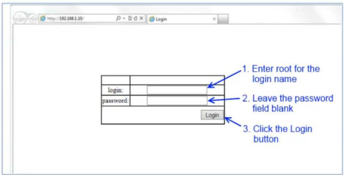
Figure 1: Login screen
SETTING THE INITIAL IP ADDRESS
Once logged in the user can now configure the switch per the network requirements. The two major addressing options are:
- Simple IP addressing
- Multiple VLAN addressing (See Add an IP to the Management VLAN on page 194).
Simple IP Addressing
A new IP address can now be assigned to the switch. From the System Information screen, go to the left hand navigation menu.
- Click on the + next to System
- Click on IP address
- Enter the desired IP address and subnet mask in the IP Address/Subnet Mask fields associated with VLAN 1
- Click the Apply & Save button (See Figure 2)

Figure 2: Assigning an IP address
CLI COMMAND USAGE
This chapter describes accessing the EtherWAN Managed Switch by using Telnet, SSH, or serial ports to configure the switch, navigating the Command Line Interface (CLI), typing keyboard shortcuts, and moving between the levels. This chapter assumes the user has a working understanding of Telnet, SSH and Terminal emulation applications.

Note: For a serial port connection use a standard DB9F to DB9M Modem Cable. The ult Serial port parameters are Baud rate: 115,200bps, Data bits: 8, Parity: none, Stop , Flow control: none.
Navigating the CLI Hierarchy
The CLI is organized into a hierarchy of command modes. The basic modes are User exec mode, Privileged exec mode, and Global configuration mode. There are also other modes, specific to certain configurations. Each mode has its own group of commands for a specific purpose. Below are the CLI commands needed to enter a specific mode:
switch_a> ← User exec mode
switch_a> enable
switch_a# ← Privileged exec mode
switch_a# configure terminal
switch_a(config) ← Global configuration mode
switch_a(config) spanning-tree mst configuration
switch_a(config-mst)# ← MSTP configuration mode

switch_a(config)# line console 0
switch_a(config-line) ← Line configuration mode

switch_a(config)# interface fe1
switch_a(config-if)# ← Interface configuration mode

switch_a(config)#vlan database
switch_a(config-vlan)# ← VLAN database configuration mode
CLI Keyboard Shortcuts
Ctrl + a: place cursor at the beginning of a line
Ctrl + b: backspace one character
Ctrl + d: delete one character
Ctrl + e: place cursor at the end of the line
Ctrl + f: move cursor forward one character
Ctrl + k: delete from the current position to the end of the line
Ctrl + I: redraw the command line
Ctrl + n: display the next line in the history
Ctrl + p: display the previous line in the history
Ctrl + u: delete entire line and place cursor at start of prompt
Ctrl + w: delete one word back
CLI Command modes
Throughout this manual, each section that has CLI commands relevant to that section requires that the CLI be in a specific configuration mode. This section shows the main CLI commands to need to enter a specific mode.
Global Configuration Mode
To set the switch to Global Configuration Mode, run the following commands from the CLI:
- enable
- configure terminal
Example:
switch_a>enable
switch_a#configure terminal
switch_a(config)#
MSTP Configuration Mode
To set the EtherWAN Managed Switch to General MSTP configuration mode, run the following commands from the CLI:
-
enable
-
configure terminal
-
spanning-tree mst configuration
Example:
switch_a>enable
switch_a#configure terminal
switch_a(config)#spanning-tree mst configuration
switch_a(config-mst)#
Interface Configuration Mode
Interface mode on the EtherWAN Managed Switch is used to configure the Ethernet ports and VLAN information. Valid interfaces are:
- fe
- 100mb ports use fe followed by the port number. Example: fe1 - ge
- Gigabit ports use ge followed by the port number. Example: ge1 - vlan1.
Example 1 configures 100mb port 1 switch_a>enable switch_a#configure terminal switch_a(config)#interface fel switch_a(config-if)
Example 2 configures VLAN ID 9 switch_a>enable switch_a#configure terminal switch_a(config)#interface vlan1.9 switch_a(config-if)
VLAN Database Configuration Mode
VLAN Database Configuration Mode on the EtherWAN Managed Switch is used to configure the VLAN settings.
Example:
switch_a>enable
switch_a#configure terminal
switch_a(config)#vlan database
switch_a(config-vlan)#
Saving a Configuration from the CLI
Example:
switch_a>enable
switch_a#write memory
Building configuration.....
[OK]
switch_a#>
SYSTEM MENU (WEB INTERFACE)
System Information
The System information link on the Left menu of the Web Configuration page takes you to a page that shows the following (see Figure 3):
- System Name
- The System name is typically used by network administrators. If SNMP is enabled on the switch, the system name can be found using MIB II (RFC1213) in the sysName property.
- Firmware Version
- If SNMP is enabled on the switch, the Firmware version can be found using MIB II in the sysDesc property
- System Time
- System time can be changed using NTP
- MAC Address
- The hardware (MAC) address of the Management interface
- Default Gateway
- The IP address of your networks Gateway (Typically a Router on your network)
- DNS Server
- The Dynamic Name Server (DNS) for your network
- System Location
- SNMP location information
- VLAN ID
○ One or more listings depending on the number of VLANs defined on the switch
- Lists VLAN ID, IP address, and subnet mask of the VLAN Interface(s)
- Current User Information
- Lists the current the currently logged in user and their user privileges
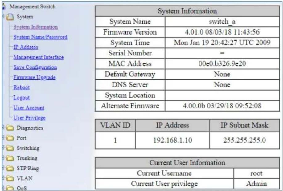
Figure 3: System Information
System Name/Password
The System name is typically used by network administrators to make it easier to document a networks infrastructure and locate equipment on large networks. If SNMP is enabled on
the switch, the system name can be found using MIB II (RFC1213) in the sysName property.
To change the system name:
- Click on the + next to System.
- Click on System Name/Password (see Figure 4).
- Use your mouse to place the cursor in the System Name text box.
- Replace the existing name with the name you want to assign to the switch.
- Click on the Update Setting button.
By default there is no password assigned to the switch. To add or change a password:
- Click on the + next to System.
- Click on System Name/Password (see Figure 4).
- Use your mouse to place the cursor in the Password text box.
- Enter the new password.
- Retype the password in the Retype Password text box.
- Click on the Update Setting button below the Retype Password text box.

NOTE: Password complexity requirements are:
Minimum of 8 and maximum of 35 characters password length, without leading or trailing spaces.
The password must contain at least one character from the following categories:
- Uppercase English letters, (A to Z), lowercase English letters, (a to z), and numbers, (0 to 9)
• Non-alphanumeric characters (such as @, #, \$), but not including (", ?, !).
User account will be locked out after 10 unsuccessful password attempts. The account will be locked out for 5 minutes.

Figure 4: System Name/Password
NOTE: To reboot the switch, press and hold the reset button for less than 10 seconds.
To reset the switch to the default password, press and hold the reset button for more than 10 seconds. This is the default function of the reset button. The reset button can also be configured to reset the entire configuration. See Configure the Reset Button.
System Name/Password using the CLI
System Name
To set the system name on a switch, use the following CLI commands (Hostname must not contain spaces. Use the dash and underscore characters):
CLI Command Mode: Global Configuration Mode
CLI Command Syntax:
hostname
no hostname
Usage Example 1: Setting a Hostname
switch_a>enable
switch_a#configure terminal
switch_a(config)#hostname switch_a
switch_a(config)#write memory
Usage Example 2: Removing a Hostname
switch a>enable
switch_a#configure terminal
switch_a(config)#no hostname
switch_a(config)#write memory
Password
To enable a password on a switch, use the following CLI commands:
CLI Command Mode: Global Configuration Mode
CLI Command Syntax:
enable password
Usage Example
switch_a>enable
switch_a#configure terminal
switch_a(config)#enable password mypassword
switch_a(config)#write memory
Show Switch Model using the CLI
For more information on CLI command usage see CLI Command Usage.
System Name
To see the model number of a switch, use the following CLI command:
CLI Command Mode: User Exec Mode or Privileged Exec Mode
CLI Command Syntax:
show integrate product series
Usage Example 1:
switch_a>enable
switch_a# show integrate product series
EX78000 series
Configure the Reset Button
Reset Button
The reset button can be configured to reset the switch password when it is pressed for thirty
seconds. This is the default function. The reset button can also reset the switch configuration when pressed for the same amount of time:
CLI Command Mode: Global config
CLI Command Syntax:
reset-button (configuration, password)
Usage Example:
switch_a(config)# reset button configuration
IP Address
To navigate to the IP Address page:
- Click on the + next to System
- Click on IP Address (see Figure 5)
There are 4 settings under the heading Static IP:
VLAN ID (IPv4) (see Simple IP Addressing)
IPv6 Enable / Disable
VLAN ID (IPv6)

DHCP Client
Use this to enable or disable DHCP on a VLAN.
To enable the DHCP Client:
- Use the drop down box to enable the DHCP client on a particular VLAN
- Click the Submit Button
DHCPv6
- This functions the same way as the DHCP Client fields, but for IPv6.
Default Gateway
If DHCP is enabled, the gateway setting is controlled by the DHCP server. The setting will be grayed out and the gateway supplied by the DHCP server will be displayed. The default gateway setting can be used when using a Static IP address. To enable the default gateway:
- Use the dropdown box to enable the default gateway.
- Type in the default gateway in the Default Gateway text box.
- Click on the Apply & Save button.
DNS Server
If DHCP is enabled, the DNS Server setting is controlled by the DHCP server. The setting will be grayed out and the DNS Server supplied by the DHCP server will be displayed. The DNS Server setting can be used when using a Static IP address. To enable the DNS Server:
- Use the dropdown box to enable the DNS Server.
- Type in the default gateway in the Default Gateway text box.
- Click on the Submit button.

Note: After making changes to settings in the IP address section, the configuration needs to be saved using the System/Save configuration page (See Save Configuration)
| DHCP Client: | ||
| DHCP Client | Disable ▼ | |
| VLAN ID | IP Address | IP Subnet Mask |
| DHCP Disable | ||
| Submit | ||
| DHCPv6 | Disable ▼ | |
| VLAN ID | IPv6 Address | Prefix Length |
| Disabled | ||
| Submit | ||
| DNS Server | Disable ▼ | |
| Submit | ||
| MAC Address | 00e0.b326.9e20 | |
Figure 5: IP Address
IP Address - Configuration using the CLI
For more information on CLI command usage see CLI Command Usage.
IP Address
To set the IP address, use the following CLI commands:
CLI Command Mode: Global Configuration Mode
CLI Command Syntax:
ip address
no ip address

Note: The Subnet Mask is defined as a Network Prefix instead of the common dotted decimal (ex. 255.255.255.0).
The most commonly used Network Prefixes are:
• /8 – Known as Class A. Also known in dotted decimal as 255.0.0.0
• /16– Known as Class B. Also known in dotted decimal as 255.255.0.0
• /24— Known as Class C. Also known in dotted decimal as 255.255.255.0
Usage Example 1: Assigning an IP address
switch_a>enable
switch_a#configure terminal
switch_a(config)#ip address 192.168.1.1/24
switch_a(config)#q
switch_a#write memory
Building configuration.....
[OK]
switch_a#q
switch_a#
Usage Example 2: Removing an IP address
switch_a>enable
switch_a#configure terminal
switch_a(config)#no ip address
switch_a(config)#q
switch_a#write memory
Building configuration....
[OK]
switch_a#q
switch_a#
Default Gateway
To set the Default Gateway, use the following CLI commands:
CLI Command Mode: Global Configuration Mode
CLI Command Syntax:
ip default-gateway
no ip default gateway
Usage Example 1: Setting the Gateway
switch_a>enable
switch_a#configure terminal
switch_a(config)#ip default-gateway 192.168.1.254
switch_a(config)#q
switch_a#write memory
Building configuration....
[OK]
switch_a#q
switch_a#
Usage Example 2: Removing the Gateway
switch_a>enable
switch_a#configure terminal
switch_a(config)#no ip default-gateway
switch_a(config)#q
switch_a#write memory
Building configuration.....
[OK]
switch_a#q
switch_a#
Domain Name Server (DNS)
To set the DNS, use the following CLI commands:
CLI Command Mode: Global Configuration Mode
CLI Command Syntax:
ip dns
Usage Example:
switch_a>enable
switch_a#configure terminal
switch_a(config)#ip dns 192.168.1.253
switch_a(config)#q
switch_a#write memory
Building configuration.....
[OK]
switch_a#q
switch_a#
Usage Example 2: Remove a DNS IP Address
switch_a>enable
switch_a#configure terminal
switch_a(config)#no ip dns
switch_a(config)#q
switch_a#write memory
Building configuration.....
[OK]
switch_a#q
switch_a#
Enable/Disable DHCP Client on a VLAN
To enable the DHCP client on a VLAN, use the following CLI commands:
CLI Command Mode: Interface Configuration Mode
CLI Command Syntax: get ip dhcp enable no get ip dhcp enable
Usage Example – Enable DHCP Client on VLAN2:
switch_a>enable
switch_a#configure terminal
switch_a(config)#interface vlan1.2
switch_a(config-if)#get ip dhcp enable
switch_a(config-if)#q
switch_a(config)#q
switch_a#write memory
Building configuration.....
[OK]
switch_a#q
switch_a#
Enable/Disable Static IP on a VLAN
To set the IP address, use the following CLI commands:
CLI Command Mode: Interface Configuration Mode
CLI Command Syntax:
ip address <A.B.C.D>
no ip address <A.B.C.D>
Usage Example 1 – Enable Static IP on VLAN2:
switch_a>enable
switch_a#configure terminal
switch_a(config)#interface vlan1.2
switch_a(config-if)#ip address 192.168.1.11
switch_a(config-if)#q
switch_a(config)#q
switch_a#write memory
Building configuration......
[OK]
switch_a#q
switch_a#
Usage Example 2 – Disable Static IP on VLAN2:
switch_a>enable
switch_a#configure terminal
switch_a(config)#interface vlan1.2
switch_a(config-if)#no ip address 192.168.1.11
switch_a(config-if)#q
switch_a(config)#q
switch_a#write memory
Building configuration.....
[OK]
switch_a#q
switch_a#
Set the IPv6 Address of an Interface
To set the IP address, use the following CLI commands:
CLI Command Mode: Interface Configuration Mode
CLI Command Syntax:
ipv6 address X:X::X:X/M
no ipv6 address (X:X::X:X/M |)
Usage Example 1 – Set IPv6 address on VLAN1:
    switch_a>enable
    switch_a#configure terminal
    switch_a(config)#interface vlan1.1
    switch_a(config-if)#ipv6 address 3ffe:506::1/48
    switch_a(config-if)#q
    switch_a(config)#q
    switch_a#write memory
Set the IPv6 Address through DHCP
To set up DHCP for IPv6 address, use the following CLI commands:
CLI Command Mode: Interface Configuration Mode
CLI Command Syntax:
get ipv6 dhcpv6 enable
no get ipv6 dhcpv6 enable
Usage Example -
switch_a>enable
switch_a#configure terminal
switch_a(config)#interface vlan1.2
switch_a(config-if)#get ipv6 dhcpv6 enable
switch_a(config-if)#q
switch_a(config)#q
switch_a#write memory
Enable/Disable DHCP Server for IPv6
To set up DHCP for IPv6 address, use the following CLI commands:
CLI Command Mode: Interface Configuration Mode
CLI Command Syntax:
dhcpv6-server enable
no dhcpv6-server enable
Usage Example -
switch_a>enable
switch_a#configure terminal
switch_a(config)#interface vlan1.2
switch_a(config-if)#dhcpv6-server enable
switch_a(config-if)#q
switch_a(config)#q
switch_a#write memory
Configure DHCPv6 server settings
To configure DHCPv6 settings, use the following CLI commands:
CLI Command Mode: Configuration Mode
CLI Command Syntax:
dhcpv6-server lease-time <0-864000>
dhcpv6-server range
Usage Example –
switch a>enable
switch a#configure terminal
switch a(config)# dhcpv6-server lease-time 5000
switch a(config)#q
switch_a#write memory
Management Interface
To navigate to the Management Interface page:
- Click on the + next to System
- Click on Management Interface
The Management Interface configuration page has three settings that allow the user to configure the methods available to manage the EtherWAN Managed Switch.
HTTPS
HTTPS (Hypertext Transfer Protocol Secure) allows the user to determine what method, if any, is used to configure the EtherWAN Managed Switch. The default is unencrypted HTTP (see Figure 6).
To disable the Web interface:
- Uncheck Http and Https.
- Click on the Update setting button.

Warning! Once the Submit button is pressed, the Web console will no longer function. As a safety precaution, the configuration is not saved by default. Rebooting the switch will restore the Web Console. To save the configuration, connect using the new IP address.
To enable the Web Interface:
- Check HTTP, HTTPS or both
- Enable Login Failure Lock if needed. This feature will lock the account for five minutes after ten unsuccessful login attempts.
- Click on the Update Setting button.
- Save the Configuration (see Save Configuration)

Warning! Enabling both HTTP and HTTPS may lead to potential security vulnerabilities. Therefore, it is suggested to only enable HTTP or HTTPS.
Telnet
Telnet is a network protocol that allows a remote computer to log into the switch to access its CLI (Command Line Interface). The CLI can be access using Telnet, SSH and the serial port on the switch. The secure method of accessing the CLI over a network is SSH.
To enable or disable Telnet:
- Click the Enable or Disable radio button in the Telnet section on the Management Interface page (see Figure 6 below)
- Click on the Update Setting button
- Save the Configuration (see Save Configuration)
SSH (Secure Shell)
Secure Shell or SSH is a network protocol that allows data to be exchanged using a secure channel between two networked devices such as a computer and the managed switch. SSH is disabled by default on the switch.
To enable or disable SSH:
- Click the Enable or Disable radio button in the SSH section on the Management Interface page (see Figure 6)
- Click on the Update Setting button
- Save the Configuration (see Save Configuration)

Figure 6: Management Interface
Management Interface Configuration using the CLI
For more information on CLI command usage see CLI Command Usage.
Enabling/Disabling Telnet
To enable or disable telnet, use the following CLI commands:
CLI Command Mode: Global Configuration Mode
CLI Command Syntax:
ip telnet
no ip telnet
Usage Example 1: Enabling Telnet:
switch_a>enable
switch_a#configure terminal
switch_a(config)#ip telnet
switch_a(config)#q
switch_a#write memory
Building configuration......
[OK]
switch_a#q
switch_a#
Usage Example 2: Disabling Telnet:
switch_a>enable
switch_a#configure terminal
switch_a(config)#no ip telnet
switch_a(config)#q
switch_a#write memory
Building configuration......
[OK]
switch_a#q

Note: If using Telnet to run the CLI Commands that disable Telnet you will lose your connection. To Disable Telnet using the CLI, use SSH or the RS-232 Console port on the switch.
Enabling/Disabling SSH
To enable or disable SSH, use the following CLI commands:
CLI Command Mode: Global Configuration Mode
CLI Command Syntax: ip ssh no ip ssh
Usage Example 1: Enabling SSH:
switch_a>enable
switch_a#configure terminal
switch_a(config)#ip ssh
switch_a(config)#q
switch_a#write memory
Building configuration.....
[OK]
switch_a#q
switch_a#
Usage Example 2: Disabling SSH:
switch_a>enable
switch_a#configure terminal
switch_a(config)#no ip ssh
switch_a(config)#q
switch_a#write memory
Building configuration......
[OK]
switch_a#q

Note: If using SSH to run the CLI Commands that disable SSH you will lose your connection. To Disable SSH using the CLI, use Telnet or the RS232 Console port on the switch.
Enabling/Disabling HTTP and/or HTTPS
To enable or disable telnet, use the following CLI commands:
CLI Command Mode: Global Configuration Mode
CLI Command Syntax:
ip http server
ip http secure-server
no ip http server
no ip http secure-server
Usage Example 1: Enabling HTTP:
switch_a>enable
switch_a#configure terminal
switch_a(config)#ip http server
switch_a(config)#q
switch_a#write memory
Building configuration.....
[OK]
switch_a#q
switch_a#
Usage Example 2: Disabling HTTP:
switch_a>enable
switch_a#configure terminal
switch_a(config)#no ip http server
switch_a(config)#q
switch_a#write memory
Building configuration....
[OK]
switch_a#q
Usage Example 3: Enabling HTTPS:
switch_a>enable
switch_a#configure terminal
switch_a(config)#ip http secure-server
switch_a(config)#q
switch_a#write memory
Building configuration.....
[OK]
switch_a#q
switch_a#
Usage Example 4: Disabling HTTPS:
switch_a>enable
switch_a#configure terminal
switch_a(config)#no ip http secure-server
switch_a(config)#q
switch_a#write memory
Building configuration......
[OK]
switch_a#q
Save Configuration Page
To navigate to the Save Configuration page:
- Click on the + next to System
- Click on Save Configuration
The Save Configuration page contains the following configuration functions (see Figure 7). Select TFTP (Trivial File Transfer Protocol) or SFTP (SSH File Transfer Protocol) to save or load a configuration.
Save Configuration
To save the currently running configuration to the flash memory:
- Click the Save Configuration button
- If the save is successful you will see the message:
Building configuration.... [OK]
Load Configuration
This function is used to load a previously saved configuration. Backing up and loading a configuration is achieved using a TFTP server.
To load a configuration:
- Enter the IP address of your TFTP server in the TFTP Server text box
- Enter the name of the configuration file in the FILE text box
- Click on the Backup button
- If the file is successfully loaded the following message will be shown: Success! System reboot is required!
Backup Configuration
This function is used to back up the current configuration of the managed switch. Backing up the configuration is achieved using a TFTP server such as TFTPD32.
To back up a configuration:
- Enter the IP address of your TFTP server in the TFTP Server text box
- Enter the name of the configuration file in the FILE text box
- Click on the Backup button
- If the backup is successful the following message will be shown:
tftpto ip success!!
Restore Default
To restore the switch to factory defaults:
- Click on the Restore Default button.
Auto Save
The Auto Save function is used to set the switch to automatically save the configuration to flash. If the saved configuration is the same as the running configuration then a save is not made. The Auto Save interval is used to determine how often the running configuration is checked for changes.
To set the Auto Save function:
- Click the dropdown box next to Auto Save.
- Set the Auto Save interval (5\~65535 sec)

Note: If a Firewall is running on the PC that is running the TFTP server, it may need to be temporarily disabled.

Figure 7: Save Configuration Page
Saving and Loading Configurations Using EB-232
The EB-232 dongle (sold separately) can save and load configuration files for EtherWAN managed switches. This improves maintenance efficiency, and allows for a failed switch to be quickly replaced with a new one running the same configuration. To use, simply plug the EB-232 into the switch's RS-232 serial interface. The various functions are described below.
Enable / Disable Automatic Restore
When the Restore function is enabled, the configuration currently saved on the EB-232 will automatically be loaded onto the switch when the EB-232 is connected to the switch's serial (RS-232) port and the switch is rebooted or power cycled. This function is enabled by default.
Save switch configuration to EB-232
By selecting this options and clicking Submit, the switch's configuration settings will be saved to the EB-232. Note that the data to be backed up will be the saved configuration on the switch regardless of what is currently running. When the save operation is complete, the Power LED will flash momentarily, and then both LEDs will light up for a few seconds. When only the green Power LED is lit, the EB-232 can be operated further on the same switch or removed.
Load switch configuration from EB-232
This operation will load configuration settings from the EB-232 to the switch. When the transfer is complete, the switch will reboot with the new settings in effect. Wait at least 3 minutes for the switch to fully reboot, then refresh the browser window (you will have to log into the web interface again). Note that the configuration loaded onto the switch includes the switch name. If you are using a specific naming convention, you will need to rename the switch and save changes.
Save configuration from TFTP server to EB-232
Use this feature to transfer switch configuration data from a TFTP server to the EB-232. Enter the TFTP server IP address and file name in the fields provided, and click Submit. When the transfer is complete, the Power LED will flash momentarily, and then both LEDs will light up for a few seconds.
Delete configuration data on EB-232
This option will erase all data from the EB-232. Data erased from the dongle in this way cannot be recovered.
Compare configuration data on EB-232 to switch
This feature will compare the configuration data on the switch with the data stored on the EB-232, notifying the user if the data differ or are identical. This allows the administrator to quickly assess if a switch is running a specific configuration.
EB-232 Firmware upgrade
Enter TFTP server IP address and file name, then click "Submit." When the EB-232 firmware has been upgraded, the Power LED will flash momentarily, and then both LEDs will light up for a few seconds.
Show firmware version on EB-232
Displays the current firmware version running on the EB-232 (not on the switch).
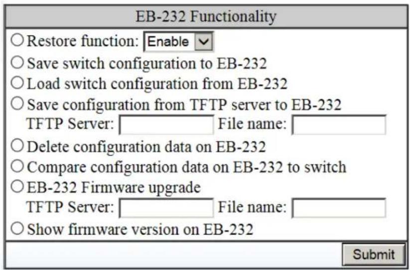
Figure 8: EB-232 Dongle Functions
Configure Reset Button
The reset button can be configured to reset the switch password when it is pressed for thirty seconds. This is the default function. The reset button can also reset the switch configuration.
| Reset Button Setting | ||
| Reset Behavior | Default Password ▼ | |
| Default Password Default Configuration Submit | ||
Show Running Configuration using the CLI
Show Configuration
CLI Command Mode: Privileged Exec Mode
CLI Command Syntax:
show running config
Control Access to show running-config
CLI Command Mode: Global Config
CLI Command Syntax:
multiuser-access show-running-config tech (hide | show) oper (hide | show)
Save Configuration Page using the CLI
Saving a Configuration
To save a running configuration, use the following CLI commands:
CLI Command Mode: Global Configuration Mode
CLI Command Syntax:
write memory
Usage Example 1: Saving a Configuration
switch_a>enable
switch_a#write memory
Building configuration......
[OK]
switch_a#q
switch_a#
To restore the switch to its default settings, use the following CLI commands:
CLI Command Mode: Privileged Exec Mode
CLI Command Syntax:
restore default
Usage Example 1: Restoring Defaults
switch_a>enable
switch_a#restore default
switch_a#q
switch_a#
Load Configuration from a TFTP Server
To Load a Configuration from a TFTP server, use the following CLI commands:
CLI Command Mode: Privileged Exec Mode
CLI Command Syntax:
install config-file
Usage Example: Loading a Configuration
switch_a>enable
switch_a#install config-file 192.168.1.100 file_name.txt
switch_a#q
switch_a#
Save Configuration to a TFTP Server
To Save a Configuration to a TFTP server, use the following CLI commands:
CLI Command Mode: Privileged Exec Mode
CLI Command Syntax:
write config-file
Usage Example: Saving a Configuration
switch_a>enable
switch_a#write config-file 192.168.1.100 flash.tgz
switch_a#q
switch_a>
Auto Save Configuration
To set the Auto Save Configuration, use the following CLI commands:
CLI Command Mode: Global Configuration Mode
CLI Command Syntax:
service auto-config enable
no service auto-config enable
service auto-config interval
Usage Example 1: Enabling Auto Save and setting the interval
switch_a>enable
switch_a#service auto-config enable
switch_a#service auto-config interval 10
switch_a#q
switch_a>
Usage Example 2: Disabling Auto Save
switch_a>enable
switch_a#no service auto-config enable
switch_a#q
switch_a>
Firmware Upgrade
To navigate to the Firmware Upgrade page:
- Click on the + next to System
- Click on Firmware Upgrade
To upgrade the switch firmware, a TFTP server is required. The firmware file is in a .TGZ or .IMG format. This is a compressed file; however, it should not be decompressed before updating the switch.
To update the firmware, (see Figure 9):
-
Copy the firmware file to the correct directory for your TFTP server. The correct directory depends on your TFTP server settings
-
Enter the filename of the firmware in the Filename text box.
- Enter the IP Address of your TFTP server in the TFTP Server IP text box.
- Click on the Upgrade button.
- During the firmware upgrade you will see the following messages. Do not reboot or unplug the switch until the final message is received.
a. Downloading now, please wait...
b. tftp
c. Firmware upgrade success!

Note: If a Firewall is running on the PC that is running the TFTP server it may need to be temporarily disabled.
| Firmware Version | 4.00.0 07/17/17 17:59:04 | |
| Filename | ||
| TFTP Server IP | ||
| Upgrade | ||
Figure 9: Firmware Upgrade Page
Firmware Update using the CLI
CLI Command Mode: Privileged Exec Mode
CLI Command Syntax:
install image
Usage Example:
switch_a>enable
switch_a#install image 192.168.1.100 flash.tgz
switch_a#q
switch_a#

Note: Depending on the firmware being loaded, the extension may not be .tgz. The
Switch does not use the extension to validate firmware.
Reboot
To navigate to the Reboot page:
- Click on the + next to System
- Click on Reboot
To reboot the switch:
- Click on the Reboot button.
- Click OK on the popup message.
Reboot using the CLI
For more information on CLI command usage see CLI Command Usage.
CLI Command Mode: Privileged Exec Mode
CLI Command Syntax: reload
Usage Example:
switch_a>enable
switch_a#reload
Reboot now, please wait...
Logout
To logout of the Web Configuration Console:
- Click on the + next to System
- Click on Logout
Logout from the CLI
CLI Command Mode: User Exec mode or Privileged Exec Mode
CLI Command Syntax:
logout
User Account Page
To navigate to the User Account page:
- Click on the + next to System
- Click on User Account
From the User Account page, multiple users can be setup with different access privileges to the switch. There are two modes that can be used, Single-User or Multi-User.
Changing the User Mode
To set the user mode (see Figure 10):
- Select Single-User, Multi-User, Radius-User or Tacacs in the dropdown box in the Multi-User Mode section. Information on Tacacs+ can be found on page 220.
- Click on the Update Setting button.
- Click OK on the Popup message that appears.

Note: Changing the user mode saves the configuration and reboots the switch.

Figure 10: User Mode
Creating a New User
To create a new user (see Figure 11):
- Choose the Create option from the dropdown list next to the User Account row heading.
- Enter a User Name (case sensitive) for the new user in the User Name text box.
- Enter a Password for the new user in the Password text box.
- Re-enter the Password in the Confirm Password text box.
- Select a Privilege Level from the dropdown list next to the Privilege Level row heading. For more information on Privilege levels see the User Privilege Configuration.
- Click on the Update button.
- Save the configuration (See the Save Configuration Page)
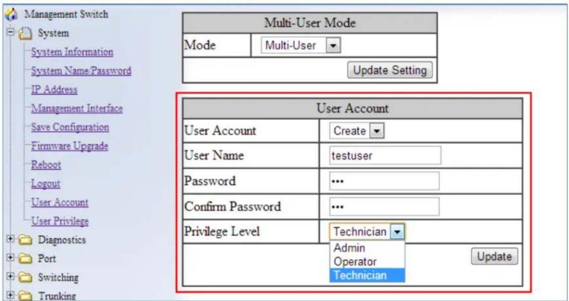
Figure 11: Creating Users
Changing an Existing User Account
To make modifications to an existing user account:
- Choose an existing user from the dropdown list next to the User Account row heading (see Figure 12).
- Change the password and/or access level following the steps in Creating a New User.
- To delete an existing user, select the user as in step 1 and then click on the Delete button (see Figure 13).
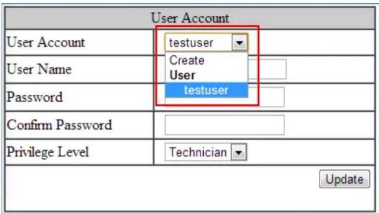
Figure 12: Selecting an Existing User Account

Figure 13: Deleting a User Account
User Privilege Configuration
To navigate to the User Privilege page:
- Click on the + next to System.
- Click on User Privilege.
There are 3 different Privilege levels on the switch.
- Admin – Has access to all configuration and administration of the switch.
- Technician – Configurable by Admin – By default no configuration ability is given.
- Operator – Configurable by Admin – By default no configuration ability is given.
The User Privilege Configuration page allows specific configuration and/or administration levels to be assigned or removed from the Technician and Operator user roles.

Note: For each function, an operator's privilege cannot be higher than a technician's
To configure the privileges for each user access level, follow the below steps:
- For each of the configuration options listed under Web function \ User Privilege (see Figure 14), select the proper privilege from the drop-down list under the appropriate user access level (Technician or Operator). The valid options are:
a. Show, Hidden, Read-Only, Read-Write
- Click on the Update button at the bottom of the page.
- Save the configuration (see Save Configuration)
| Web Function \ User Privilege | Technician | Operator | Detail |
| System | Show | Show | |
| System Information | Show | Show | |
| System Name/Password | Hidden | Hidden | |
| IP Address | Read-Only | Read-Only | |
| Management Interface | Read-Only | Read-Only | |
| Save Configuration | Hidden | Hidden | |
| Firmware Upgrade | Hidden | Hidden | |
| Reboot | Hidden | Hidden | |
| Logout | Show | Show | |
| User Account | Hidden | Hidden | |
| User Privilege | Hidden | Hidden | |
| Diagnostics | Show | Show | |
| Utilization | Show | Show | |
| System Log | Show | Show | |
| Remote Logging | Read-Only | Read-Only | |
| APP Table | Show | Show |
Figure 14: User Privilege Page
User Account Settings using the CLI
For more information on CLI command usage see CLI Command Usage.
Multi-User Mode
To enable the multi-user feature, use the following CLI commands:
CLI Command Mode: Line Configuration Mode
CLI Command Syntax: login local
Usage Example:
switch_a>enable
switch_a#configure terminal
switch_a(config)#line console 0
switch_a(config-line)#login local
% Switching Single/Multi/Radius-User mode need to reboot the switch to take effect!
switch_a(config-line)#q
switch_a(config)#q
switch_a#
Single User Mode
To enable the single-user feature, use the following CLI commands:
CLI Command Mode: Line Configuration Mode
CLI Command Syntax: login
Usage Example:
switch_a>enable
switch_a#configure terminal
switch_a(config)#line console 0
switch_a(config-line)#login
% Switching Single/Multi/Radius-User mode need to reboot the
switch to take effect!
switch_a(config-line)#q
switch_a(config)#q
switch_a#
Radius User Mode
To enable the radius-user feature, use the following CLI commands:
CLI Command Mode: Line Configuration Mode
CLI Command Syntax: login radius
Usage Example:
switch_a>enable
switch_a#configure terminal
switch_a(config)#line console 0
switch_a(config-line)#login radius
% Switching Single/Multi/Radius-User mode need to reboot the
switch to take effect!
switch_a(config-line)#q
switch_a(config)#q
switch_a#
Tacacs User Mode
To enable the Tacacs-user feature, use the following CLI commands:
CLI Command Mode: Line Configuration Mode
CLI Command Syntax: login tacplus
Usage Example:
switch_a>enable
switch_a#configure terminal
switch_a(config)#line console 0
switch_a(config-line)#login tacplus
% Switching Single/Multi/Radius/Tacacs-User mode need to reboot the switch to take effect!
switch_a(config-line)#q
switch_a(config)#q
switch_a#
Creating a New User
To create a new user, use the following CLI commands:
CLI Command Mode: Global Configuration Mode
CLI Command Syntax:
username
characters>

Note: The optional <8> CLI command after the CLI command password is used to specify that the password should be displayed in encrypted form in the configuration file.
Usage Example:
switch_a>enable
switch_a#configure terminal
switch_a(config)#username user1 privilege operator password 1234
switch_a(config)#username user1 privilege operator password 8 1234
switch_a(config)#username user2 privilege technician password 4321
switch_a(config)#username user2 privilege technician password 8 4321
switch_a(config)#username user3 privilege admin password 5678
switch_a(config)#username user3 privilege admin password 8 5678
switch_a(config)#q
switch_a#
Permissions
Permissions must be set using the Web GUI. See User Privilege Configuration.
DIAGNOSTICS
Utilization
To navigate to the Utilization page:
- Click on the + next to Diagnostics.
- Click on Utilization.
The Utilization page shows (see Figure 15):
• CPU Utilization – Current and Max Utilization
• Memory Utilization – Total, Used and Free Memory
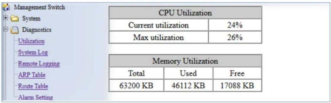
Figure 15: Utilization Page
System Log
To navigate to the System Log page:
- Click on the + next to Diagnostics.
- Click on System Log.
In addition to saving the system logging messages in the memory (RAM) of the switch, messages can be also saved into the switch's non-volatile memory (flash). Messages saved on the flash memory persist even when the switch is rebooted.
Log Severity Levels
Each log message contains a Severity field that indicates the severity of the event that caused the log message. For each log destination, you can define a severity level threshold.
This switch will filter log messages based on severity level. A message will be logged to permanent memory (Flash) or the RAM when a message's severity level is less than or equal to this setting. This change will take effect immediately. Each of the RAM and the Flash has its own severity setting.
Examples:
Set the level to value 3. All messages with severity level from 0 (Emergency) to 3 (Error) will be saved to the flash.
Set the level to value 7. All messages with severity level from 0(Emergency) to 7(Debug) will be saved to the flash.
To configure system log settings (see Figure 16):
-
Select a Severity Level from 0 to 7 for messages saved to RAM or Flash memory. A message will be logged to permanent memory (Flash) or the RAM when a message's severity level is less than or equal to this setting.
-
Click a radio button next to either Flash or Memory to view the logs on that medium.
-
Select Enable or Disable for Auto Refresh, and select the maximim number of messages to be viewed on one page.
-
Click Update Setting.
| System Log Setting | |
| Permanent Memory(Flash) | |
| Severity Level | 4 ▼ |
| Memory | |
| Severity Level | 4 ▼ |
| Log Display | |
| View Messages From | ● Flash ● Memory |
| Auto Refresh | Disable ▼ |
| Max Number of Messages Per Page | 50 ▼ |
| Update Setting | |
Figure 16: System Log Setting
At the bottom of the screen, the System Log shows the logs for either Permanent Memory (Flash) or Memory (RAM), depending on the System Log Settings (above). Use the Clear Log button to clear the System Log for the selected medium.
| System Log(Flash) | |
| 1 | At Jan 9 02:22:26 Accounting user.err(3) systemlog.cgi: MSG_FAIL_GEN!! |
| 2 | At Jan 9 02:22:26 Accounting user.err(3) systemlog.cgi: MSG_FAIL_GEN!! |
| 3 | At Jan 9 02:22:26 Accounting user.err(3) systemlog.cgi: MSG_FAIL_GEN!! |
| 4 | At Jan 9 02:22:26 Accounting user.err(3) systemlog.cgi: MSG_FAIL_GEN!! |
Figure 17: System Log
System log using CLI commands
Configure the message view in the GUI.
CLI Command Mode: Global config
CLI Command Syntax:
system-log display permanent
system-log display memory
Usage Example:
switch_a(config)# system-log display memory
System Log general configuration – set severity for saved logs. Storage location: Flash (permanent memory). This command will take effect immediately.
CLI Command Mode: Global config
CLI Command Syntax:
switch_a(config)# system-log severity permanent <0-7>
Usage Example:
switch_a(config)# system-log severity permanent 5
Set severity for saved logs - Storage location: Memory (RAM). This command will take effect immediately.
CLI Command Mode: Global config
CLI Command Syntax:
switch_a(config)# system-log severity memory <0-7>
Usage Example:
switch_a(config)# system-log severity memory 5
Configure Auto Refresh on the WebUI (in number of minutes). The messages on the web page will be refreshed automatically, at the specified interval. However, this command applies to the first page of messages only.
CLI Command Mode: Global config
CLI Command Syntax:
system-log page refresh (disable | 1 | 2 | 5 | 10)
Usage Example:
switch_a(config)# system-log page refresh 10
Configuring Page Size. Specify the maximum number of messages to be displayed with each SHOW command. This command applies to flash view only.
CLI Command Mode: Global config
CLI Command Syntax:
system-log page size (50 | 100 | 200 | 1000)
Usage Example:
switch_a(config)# system-log page size 50
Clear the Log. Clear all messages in flash or memory.
CLI Command Mode: Global config
CLI Command Syntax:
Flash
system-log permanent clear
Memory
system-log clear
Usage Example:
switch_a(config)# system-log clear
Show commands. Display messages stored in the flash (permanent memory) or in memory (RAM).
CLI Command Mode: Exec Mode or Privileged Exec Mode
CLI Command Syntax:
Flash
show system-log permanent (first | next | prev)
Memory
show system-log
Usage Example:
switch_a(config)# show system-log
Remote Logging
To navigate to the Remote Logging page:
- Click on the + next to Diagnostics.
- Click on Remote Logging.
Remote Logging to a Syslog server allows administrators to log important system and debugging information. The Remote Logging configuration page allows reporting to a Syslog server to be enabled or disabled as well as management of a list of Syslog servers to report to (see Figure 18).
To configure Remote Logging:
- Click on the Enable or Disable radio button under Remote Logging.
- Click on the Update Setting button.
To add a Syslog server:
- Enter the IP Address of the Syslog Server in the Syslog Server IP text box.
- Click on the Add Syslog Server button.
To delete a Syslog server from the list of servers currently on the switch:
- Select the Syslog server from the Drop down box

2. Click on the Delete Syslog Server button

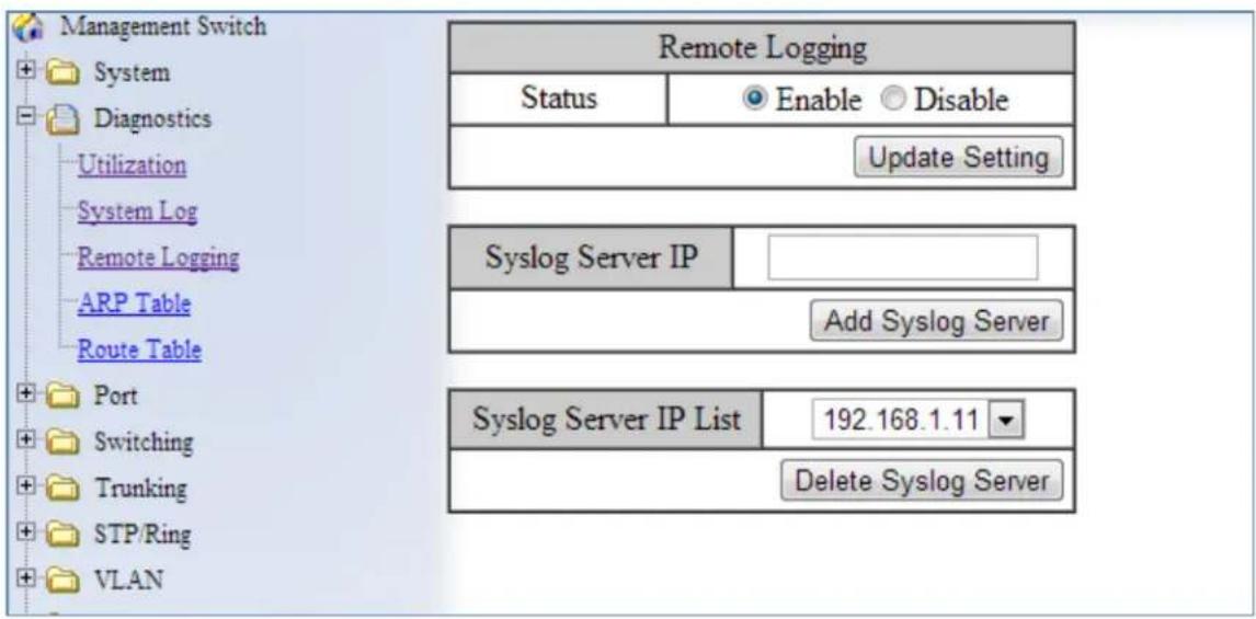
Figure 18: Remote Logging Page
Remote Logging using CLI commands
For more information on CLI command usage see CLI Command Usage.
Enable/Disable Remote Logging
CLI Command Mode: Global Configuration Mode
CLI Command Syntax:
remote-log enable
no remote-log enable
Usage Example 1: Enable Remote Logging
switch a>enable
switch_a#remote-log enable
switch_a#q
switch_a#
Usage Example 2: Disable Remote Logging
switch_a>enable
switch_a#no remote-log enable
switch_a#q
switch_a#
Add/Delete a Remote Logging Host
CLI Command Mode: Global Configuration Mode
CLI Command Syntax:
remote-log add
remote-log del
remote-log del all
Usage Example 1: Add a Remote Logging Host
switch a>enable
switch a#remote-log add 192.168.1.100
switch_a#q
switch_a#
Usage Example 2: Delete a Remote Logging Host
switch_a>enable
switch_a#remote-log del 192.168.1.100
switch_a#q
switch_a#
ARP Table
To navigate to the ARP Table page:
- Click on the + next to Diagnostics.
- Click on ARP Table.
The ARP Table page shows ARP (Address Resolution Protocol) entries that are stored in the Switches ARP Table. This is useful for System Administrators for troubleshooting purposes. The information shown is:
• IP Address of the listed device
- Hardware Type – For Ethernet devices this will always be 1.
- Flags
○ 2 = Device responded to ARP Request
○ 0 = No response to ARP Request
- Hardware Address – MAC Address of the listed device
• VLAN – The VLAN that the listed device is on
| Management Switch System Diagnostics Utilization System.Log Remote Logging ARP Table Route Table Port Switching Trunking STP/Ring VLAN QoS ACL SNMP 8021X LLDP | ARP Table | |||||
| IP Address | Hardware Type | Flags | Hardware Address | Mask | VLAN | |
| 10.58.7.114 | 1 | 2 | 00:18:8B:5B:B7:11 | * | 1 | |
| 10.58.7.112 | 1 | 2 | 90:18:7C:1F:D0:2B | * | 1 | |
| 10.58.7.113 | 1 | 2 | BC:30:5B:C7:43:49 | * | 1 | |
| 10.58.7.119 | 1 | 2 | 5C:51:4F:10:E9:01 | * | 1 | |
| 10.58.7.117 | 1 | 2 | 2C:B4:3A:EB:7C:AE | * | 1 | |
| 10.58.7.81 | 1 | 2 | 00:25:64:50:82:37 | * | 1 | |
| 10.58.7.105 | 1 | 0 | 00:00:00:00:00:00 | * | 1 | |
| 10.58.7.32 | 1 | 2 | 9C:93:4E:19:38:57 | * | 1 | |
| 10.58.7.107 | 1 | 2 | 00:50:B6:65:2A:22 | * | 1 | |
| 10.58.7.106 | 1 | 2 | 00:26:B9:88:49:4B | * | 1 | |
| 10.58.7.7 | 1 | 2 | B8:A3:86:56:E2:9E | * | 1 | |
| 10.58.7.109 | 1 | 2 | 00:18:8B:5B:B2:AA | * | 1 | |
| 10.58.7.1 | 1 | 2 | 00:16:B6:86:67:14 | * | 1 | |
| 10.58.7.110 | 1 | 2 | 00:4F:4B:53:39:93 | * | 1 | |
Figure 19: ARP Table
ARP Table using CLI Commands
For more information on CLI command usage see CLI Command Usage.
CLI Command Mode: Global Configuration Mode
CLI Command Syntax:
show arp-table
Usage Example:
switch_a>enable
switch_a#show arp-table
IP address HW type Flags HW address Mask VLAN
10.58.7.130 1 2 00:50:B6:65:2A:22 * 1
switch_a#q
switch_a#
Route Table
To navigate to the Route Table page:
- Click on the + next to Diagnostics.
- Click on Route Table.
The Route Table lists the routes to network destinations and metrics (distances) that are associated with those routes. The Route Table contains information about the topology of the network around it.
| Route Table | |||||||
| Destination | Gateway | Genmask | Flags | Metric | Ref | Use | VLAN |
| 192.168.1.0 | 0.0.0.0 | 255.255.255.0 | U | 0 | 0 | 0 | 2 |
| 10.58.7.0 | 0.0.0.0 | 255.255.255.0 | U | 0 | 0 | 0 | 1 |
| 0.0.0.0 | 10.58.7.1 | 0.0.0.0 | UG | 0 | 0 | 0 | 1 |
Figure 20: Route Table
Route Table Using CLI Commands
For more information on CLI command usage see CLI Command Usage.
CLI Command Mode: Global Configuration Mode
CLI Command Syntax:
show route-table
Usage Example:
switch_a>enable
switch_a#show route-table
Destination Gateway Genmask Flags Metric Ref Use VLAN
10.58.7.0 0.0.0.0 255.255.255.0 U 0 0 0 1
switch_a#q
switch_a#
Alarm Setting
This setting applies only to Switch models that have a hardware relay.
To navigate to the Alarm Setting page:
- Click on the + next to Diagnostics.
- Click on Alarm Setting.
The Alarm Setting page allows users to define Ethernet port Link-down and Power failure alarms for triggering an alarm using the relay on the switch.
To configure an Ethernet port or Power input:
- Select an Ethernet port or Power input from the dropdown box (see Figure 21).
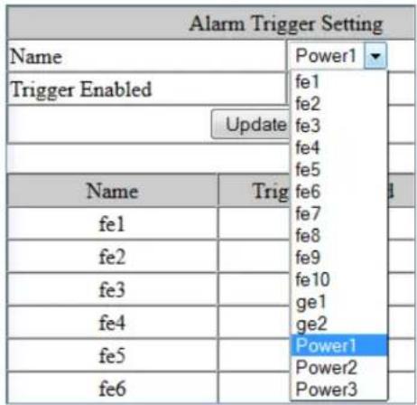
Figure 21: Alarm Trigger
- Select YES or NO from the dropdown box next to Trigger Enabled (see Figure 22).
- Click Update Setting to save any changes made.

Figure 22: Trigger Enable
To configure the normal state for the alarm relay, check the corresponding radio button for either closed or open, and click Update Setting.
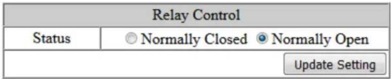
Figure 23: Relay Control
Alarm Setting Using CLI Commands
For more information on CLI command usage see CLI Command Usage.
CLI Command Mode: Global Configuration Mode
CLI Command Syntax:
alarm-trigger if
no alarm-trigger if
Usage Example:
Enable alarm on interface fe1
switch_a>enable
switch_a#conf t
switch_a(config)alarm-trigger if fel
switch_a(config)#q
switch_a#
Enable alarm on input power 2
switch_a>enable
switch_a#conf t
switch_a(config)alarm-trigger power 2
switch_a(config)#q
switch_a#
Set Normal State for Alarm Relay
This command is only available in models with Power over Ethernet (PoE) functionality.
For more information on CLI command usage see CLI Command Usage.
CLI Command Mode: Global Configuration Mode
CLI Command Syntax:
closed-on-alarm
open-on-alarm
Usage Example:
Set the alarm relay normal state to closed
switch_a>enable
switch_a#conf t
switch_a(config)relay closed-on-alarm
switch_a(config)#q
switch_a#
NOTE: The hardware relay on the PoE switch is normally open. This means that if all power is lost on the switch the relay will revert to the open position, and not signal an alarm,
regardless of the relay closed-on-alarm setting. The relay closed-on-alarm command is only used to set the switch to close the relay in an alarm condition other than all power lost. If using a closed relay position to indicate an alarm, the alarm will not function if all power is lost to the switch.
Configuring Email Alarm Notifications
The switch can send email alerts to up to three recipients when an environmental alarm is triggered.
To enable email notifications:
- Choose Enable from the drop down menu in the SMTP Server field.
- Click on the Update Setting button under the field.
To configure mail server and recipient email addresses:
- Enter the name of the SMTP server to be used in the corresponding field, and the server port.
- Enter the email address of the sending account.
- Enter the password for the email account being used, and select Enable or disable for SSL (Secure Sockets Layer).
- Click the Update button.
NOTE: If SSL is disabled, port 25 will be used to send email. If SSL is enabled, port 465 will be used.
You can view, add, and delete email recipients in the fields at the bottom of the page. Only one email address can be added at a time.

Email Alarm Notifications Using CLI Commands
To send a test mail with a timeout of 60 seconds:
CLI Command Mode: Privileged exec mode
CLI Command Syntax:
msmtp event-email send test
To configure email alarm settings and parameters:
CLI Command Mode: Global config
To set SMTP authentication for SMTP server, port, username, password, and SSL.
CLI Command Syntax: msmtp auth host WORD
msmtp auth passwd WORD
msmtp auth port <1-65535>
msmtp auth ssl
msmtp auth username WORD
Usage Example:
switch_a(config)#msmtp auth host smtp.companyserver.com
switch a(config)#msmtp auth passwd abcppwqabc
switch a(config)#msmtp auth port 50
switch a(config)#msmtp auth ssl
switch a(config)#msmtp auth username user@domain.com
Enable/disable email alerts.
CLI Command Syntax: [no] msmtp enable
Set recipients for email alerts. Up to three email addresses can be entered.
CLI Command Syntax: [no] msmtp event-email recipient WORD
Usage Example:
switch_a(config)#msmtp event-email recipient
sysadmin@company.com;user@domain.com
Set SMTP server authentication, port, username, password, and SSL).
CLI Command Syntax: msmtp host WORD
msmtp port <1-65535>
msmtp username WORD
msmtp passwd WORD
msmtp ssl
Usage Example:
switch_a(config)#msmtp host smtp.companyserver.com
switch_a(config)#msmtp passwd abcppwqabc
switch_a(config)#msmtp port 50
switch_a(config)#msmtp ssl
switch_a(config)#msmtp username user@domain.com
PORT
Configuration
To navigate to the Configuration page:
- Click on the + next to Port.
- Click on Configuration.
Port configuration contains such useful features as flow control, port speed, and duplex settings. Some users will find these settings very valuable such as when the switch is connect to a latency-critical device such as a VOIP phone or IP camera or video multiplexor. In these cases and others the ability to alter the port settings can make the difference between a poorly responding device and one that functions without loss of data or clarity.
.The Configuration page shows (see Figure 24):
- Port Number – fe(n) for 100mb ports and ge(n) for Gigabit ports
- Link Status – Operational State of the Port's Link (Read-Only)
- Port Description – User-supplied Port Description
- Admin Setting – Administratively Enable or Disable the Port.
• Speed – Speed and Duplex Settings for Port. - Flow Control – State of Flow Control for the Port.
To provide a description to a port:
- Click in the Description text box for the appropriate port.
- Type in the description of the port.
- Click on the Submit button.
To enable or disable a port:
- Click on the drop-down box under Admin Setting and select either Link Up or Link Down.
- Click on the Submit button.
To set the Port Speed and/or Port Duplex Settings:
-
Click on the drop-down box under Speed and select the desired port speed / duplex settings for that port. Please note, not all port types will have the same options. For example, 100Mb fiber ports will typically be limited to a single option of 100M/FD (100Mbps and Full Duplex) while running 1Gb UTP ports will have six options for speed/duplex.
-
Click on the Submit button.
To enable or disable a port's Flow Control settings:
- Click on the drop-down box under Flow Control and select either Enable or Disable.
- Click on the Submit button.
| Port | Link Status | Port Description | Admin Setting | Speed | Flow Control |
| fe1 | Running | Link Up ▼ | Auto ▼ | Enable ▼ | |
| fe2 | Down | Link Up ▼ | Auto ▼ | Enable ▼ | |
| fe3 | Down | Link Up ▼ | Auto ▼ | Enable ▼ | |
| fe4 | Down | Link Up ▼ | Auto ▼ | Enable ▼ | |
| fe5 | Down | Link Up ▼ | Auto ▼ | Enable ▼ | |
| fe6 | Down | Link Up ▼ | Auto ▼ | Enable ▼ | |
| fe7 | Down | Link Up ▼ | Auto ▼ | Enable ▼ | |
| fe8 | Down | Link Up ▼ | Auto ▼ | Enable ▼ | |
| ge1 | Down | Link Up ▼ | Auto ▼ | Enable ▼ | |
| ge2 | Down | Link Up ▼ | Auto ▼ | Enable ▼ | |
Figure 24: Port Configuration
Port Status
To navigate to the Port Status page:
- Click on the + next to Port.
- Click on Port Status.
This page is a read-only page that lists the settings described in the previous section. It is useful if all the user intends to do is read the values of the port settings, not modify the port settings. .The Port Status page shows (see Figure 25):
- Port Number – fe(n) for 100mb ports and ge(n) for Gigabit ports
- Link Status – Operational State of the Port's Link
• Medium type – Indicates whether the cable is copper or fiber - Port Description – User-supplied Port Description
• Speed – Speed Settings for Port - Duplex – Duplex status
• Flow Control – State of Flow Control for the Port
| Port | Medium Type | Link Status | Port Description | Speed | Duplex | Flow Control |
| fe1 | copper | Running | 100M | Auto | Disable | |
| fe2 | copper | Running | 100M | Auto | Disable | |
| fe3 | copper | Down | 100M | Auto | Disable | |
| fe4 | copper | Running | 100M | Auto | Disable | |
| fe5 | copper | Down | 100M | Auto | Disable | |
| fe6 | copper | Down | 100M | Auto | Disable | |
| fe7 | copper | Down | 100M | Auto | Disable | |
| fe8 | copper | Down | 100M | Auto | Disable | |
| ge1 | SFP | Down | 1000M | Auto | Disable | |
| ge2 | SFP | Down | 1000M | Auto | Disable |
Figure 25: Port Status
Rate Control
To navigate to the Rate Control page:
- Click on the + next to Port.
- Click on Rate Control.
The Rate Control page allows the user to set the maximum throughput on a port or ports on both packets entering the port (from the connected device) or packets leaving the port.
The Ingress text box controls the rate of data traveling into the port while the Egress text box controls the rate of data leaving the port.

Note: Entries will be rounded down to the nearest acceptable rate value. If the value entered is below the lowest acceptable value then the lowest acceptable value will be used.
The Rate Control page is shown below (see Figure 26):
To provide either an ingress or egress rate control for a port:
- Click in the Ingress or Egress Text Box for the appropriate port.
- Type in the ingress/egress rate for the port according to the values listed above.
- Click on the Update Setting button.
| Port | Ingress | Egress | ||
| fe1 | 992 kbps | 800 kbps | ||
| fe2 | 0 kbps | 0 kbps | ||
| fe3 | 0 kbps | 0 kbps | ||
| fe4 | 0 kbps | 0 kbps | ||
| fe5 | 0 kbps | 0 kbps | ||
| fe6 | 0 kbps | 0 kbps | ||
| fe7 | 0 kbps | 0 kbps | ||
| fe8 | 0 kbps | 0 kbps | ||
| ge1 | 0 kbps | 0 kbps | ||
| ge2 | 0 kbps | 0 kbps | ||
| Update Setting | ||||
Figure 26: Rate Control
RMON Statistics
To navigate to the RMON Statistics page:
- Click on the + next to Port.
- Click on RMON Statistics.
RMON Statistics gives a detailed listing of the types and quantity of packets that a particular port has seen since the last reboot of the switch (see Figure 27).
To view the RMON statistics for a particular:
- Click on the link to the port at the top of the RMON Statistics page.
To clear the RMON statistics for a particular port:
- Click on the link to the port at the top of the RMON Statistics page.
- Click on the Clear button at the bottom of the page.
- The statistics for the port will update every ten seconds.

Pay particular attention to the values for CRC/Alignment errors and collisions. Nonzero values for these fields can indicate that a port speed or duplex mismatch exists on the port.
| fe1 | fe2 | fe3 | fe4 | fe5 | fe6 |
| fe7 | fe8 | fe9 | fe10 | ge1 | ge2 |
| Port 1/fel Statistics | |||||
| Drop Events | 0 | ||||
| Broadcast Packets Received | 836467 | ||||
| Multicast Packets Received | 1584880 | ||||
| Undersize Packets Received | 0 | ||||
| Oversize Packets Received | 0 | ||||
| Fragments Packets Received | 0 | ||||
| 64-byte Packets Received | 606350 | ||||
| 65 to 127-byte Packets Received | 381794 | ||||
| 128 to 255-byte Packets Received | 321375 | ||||
| 256 to 511-byte Packets Received | 961517 | ||||
| 512 to 1023-byte Packets Received | 163465 | ||||
| 1024 to 1518-byte Packets Received | 4339 | ||||
| Jabber Packets | 0 | ||||
| Bytes Received | 574580429 | ||||
| Packets Received | 2438841 | ||||
| Collisions | 0 | ||||
| CRC/Alignment Errors Received | 0 | ||||
| TX No Errors | 312082 | ||||
| RX No Errors | 2438841 | ||||
| Status of statistics will be refresh per 30 seconds after click Clear. | |||||
| Clear | |||||
Figure 27: RMON Page
Per Port VLAN Activities
To navigate to the Per Port VLAN Activities page:
- Click on the + next to Port.
- Click on Per Port VLAN Activities.
This is a read-only page that will allow the user to see what devices are connected to a particular port and the vlan associated with that device and port.
To clear the MAC addresses for a particular port (see Figure 28):
-
Click on the link to the port at the top of the Per Port VLAN Activities page.
-
Click on the Clear MAC button at the bottom of the page.
-
The statistics for the port will update every ten seconds.

Figure 28: Port VLAN Activities
Port Security
To navigate to the Port Security page:
- Click on the + next to Port.
- Click on Port Security.
One way for an attacker to gain unauthorized access to a network is by connecting to an available port on an unsecured switch. By default, there is no limit to the number of MAC addresses that can be accessed by a port, and no prohibited MAC addresses. The Port Security feature can be used to prevent this kind of unauthorized network access.
Port Security uses dynamically or statically learned MAC addresses to restrict ingress traffic by limiting the MAC address that are allowed to send traffic to the port. Port Security is disabled by default.
There are two options for configuring Port Security:
The Enable mode is for the manual entry of static MAC addresses for a port. It is the most common method but requires much effort and time. The maximum number of static MAC addresses that can be set per port is 256.
Sticky mode allows an interface to dynamically (learn automatically) the MAC address of the connected device, and afterwards will only accept packets from that MAC address. Only one MAC address is set for each port in this mode.
To set a port to dynamically learn MAC addresses from connected devices:
- Select Sticky from the Mode column for the port you want to configure.
- Click the Update Setting button.
The first MAC address learned dynamically from the connected port will be shown in the Add MAC address field if the page is reloaded. Existing static MAC addresses (set from enable mode) for the port will not be converted to sticky MAC addresses for the port.
To remove a static MAC address from a port:
- Select the MAC address from the dropdown list in the Delete MAC address column next to the port that you want to configure.
- Click the Update Setting button.
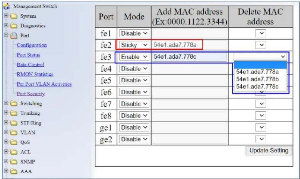
Figure 29: Port Security
Using Port Security with Multiple VLANs
If creating VLANs while using the Port Security feature, the PVID is what determines if the VLAN will pass packets. If different VLANs have the PVID, then packets will be allowed to pass. If the PVID is different for the VLANs, then packets will not be allowed to pass.
Once the PVID has been changed, then Port Security must be disabled and then re-enabled for the new PVID to take effect. In the following example, switch port 1 is connected to computer 1.
Step 1: Enable port1 Port Security sticky (default PVID=1).
switch_a(config)#int fel
switch_a(config-if)# port-security mac-address sticky
switch_a(config-if)#
Step 2: Get dynamic Mac address from computer 1.
switch_a#show port-security address
Secure Mac Address Table
VID Ports Mac Address Type
1 fel 408d.5ccf.4c88 dynamic
switch_a#
Step 3: Change PVID from 1 to 10. Now port security will not work. (PVID=10)
switch_a(config)#vlan database
switch_a(config-vlan)#vlan 10 bridge 1
switch_a(config-vlan)#exit
switch_a(config)#int fel
switch_a(config-if)#switchport
access hybrid mode portbase trunk
switch_a(config-if)#switchport hybrid vlan
switch_a(config-if)#switchport hybrid vlan 10
Step 4: Because the PVID has been changed, Port Security must be set again.
switch_a(config)#int fel
switch_a(config-if)#no port-security
allowed-address enable sticky
switch_a(config-if)#no port-security sticky
switch_a(config-if)#port-security mac-address sticky
switch_a(config-if)#exit
switch_a(config)#exit
switch_a#show port-security address
Secure Mac Address Table
----
VID Ports Mac Address Type
----
10 fel 408d.5ccf.4c88 dynamic
switch_a#
Step 5: Save dynamic Mac address to startup-config.
switch_a#
switch_a#write
Building configuration......
[OK]
switch_a#
Port Configuration Examples Using CLI Commands
For more information on CLI command usage see CLI Command Usage.
Setting the Port Description
To provide a description of a port use the CLI commands below:
CLI Command Mode: Interface Configuration Mode
CLI Command Syntax: description
Usage Example:
switch_a>enable
switch_a#configure terminal
switch_a(config)#int fel
switch_a(config-if)#description A_Port_Description
switch_a(config-if)#q
switch_a(config)#
Enable or Disable a Port
To administratively enable or disable a port use the CLI commands below:
CLI Command Mode: Interface Configuration Mode
CLI Command Syntax:
shutdown
no shutdown
Usage Example 1: Disabling a port:
switch_a>enable
switch_a#configure terminal
switch_a(config)#int fel
switch_a(config-if)#shutdown
switch_a(config-if)#q
switch_a(config)#
Usage Example 2: Enabling a port:
switch_a>enable
switch_a#configure terminal
switch_a(config)#int fe1
switch_a(config-if)#no shutdown
switch_a(config-if)#q
switch_a(config)#
Setting the Port Speed
To set the port speed for a port use the CLI commands below:
CLI Command Mode: Interface Configuration Mode
CLI Command Syntax: bandwidth <1-10000000000 bits> (usable units : k, m, g)
Usage Example:
switch_a>enable
switch_a#configure terminal
switch_a(config)#int fel
switch_a(config-if)#bandwidth 100m
switch_a(config-if)#q
switch_a(config)#q
switch_a#
Setting Port Duplex
To set the duplex for a port use the CLI commands below:
CLI Command Mode: Interface Configuration Mode
CLI Command Syntax: duplex
Usage Example:
switch_a>enable
switch_a#configure terminal
switch_a(config)#int fel
switch_a(config-if)#duplex full
switch_a(config-if)#q
switch_a(config)#
Enable or Disable Port Flow Control
To enable or disable flow control for a port use the CLI commands below:
CLI Command Mode: Interface Configuration Mode
CLI Command Syntax: flowcontrol on
Usage Example:
switch_a>enable
switch_a#configure terminal
switch_a(config)#int fe1
switch_a(config-if)#flowcontrol on
switch_a(config-if)#q
switch_a(config)#
Display Port Status
To display the port status for a port use the CLI commands below:
CLI Command Mode: Privileged Exec Mode
CLI Command Syntax: show interface
Usage Example:
switch_a>enable
switch_a#show interface fe1
Setting a Port's Rate Control
To set a ports rate control use the CLI commands below:
CLI Command Mode: Interface Configuration Mode
CLI Command Syntax: rate-control
Usage Example:
switch_a(config-if)#rate-control ingress value 100000
Display a Port's RMON Statistics
To display a ports RMON statistics use the CLI commands below:
CLI Command Mode: Privileged Exec Mode
CLI Command Syntax: show interface statistics
Usage Example:
switch_a#show interface statistics fel
Display a Port's VLAN Activities
To display a port's VLAN activities use the CLI commands below:
CLI Command Mode: Privileged Exec Mode
CLI Command Syntax: show bridge interface
Usage Example:
switch_a#show bridge interface fe1
Disable Port on Link Down
As a security feature, a port can be configured to automatically shut down when it becomes disconnected. When this feature takes effect, the port must be re-enabled manually.
CLI Command Mode: Interface Configuration Mode
CLI Command Syntax: [no] linkdown-disable
Usage Example:
switch_a>enable
switch_a#configure terminal
switch_a(config)#int fe1
switch_a(config-if)#linkdown-disable
Enable MAC port security
To enable MAC port security, use the CLI commands below:
CLI Command Mode: Interface Configuration Mode
CLI Command Syntax: port-security enable
Usage Example:
switch_a>enable
switch_a#configure terminal
switch_a(config)#int fel
switch_a(config-if)# port-security enable
switch_a(config-if)#q
Disable MAC port security
To disable MAC port security, use the CLI command below. Note that this command will clear all MAC address that have been created, both statically and dynamically.
CLI Command Mode: Interface Configuration Mode
CLI Command Syntax: no port-security enable
Usage Example:
switch_a>enable
switch_a#configure terminal
switch_a(config)#int fel
switch_a(config-if)#no port-security enable
switch_a(config-if)#q
Assign MAC Addresses for Port Security
To set the allowed MAC addresses (maximum of 256 per port), use the CLI commands below:
CLI Command Mode: Interface Configuration Mode
CLI Command Syntax: port-security allowed-address
Usage Example:
switch_a>enable
switch_a#configure terminal
switch_a(config)#int fe1
switch_a(config-if)#port-security allowed-address
00aa.0062.c609
switch_a(config-if)#q
Delete MAC Address for Port
To delete an allowed MAC address use the CLI commands below:
CLI Command Mode: Interface Configuration Mode
CLI Command Syntax: no port-security allowed-address
Usage Example:
switch_a>enable
switch_a#configure terminal
switch_a(config)#int fe1
switch_a(config-if)# no port-security allowed-address
00aa.0062.c609
switch_a(config-if)#q
Set Port Security to Sticky Mode
To set sticky mode, use the CLI command below:
CLI Command Mode: Interface Configuration Mode
CLI Command Syntax: port-security mac-address sticky
Usage Example:
switch_a>enable
switch_a#configure terminal
switch_a(config)#int fel
switch_a(config-if)# port-security mac-address sticky
switch_a(config-if)#q
Disable Sticky Mode
To disable sticky mode, use the CLI commands below:
This command will clear MAC addresses previously acquired via sticky mode.
CLI Command Mode: Interface Configuration Mode
CLI Command Syntax: no port-security mac-address sticky
Usage Example:
switch_a>enable
switch_a#configure terminal
switch_a(config)#int fel
switch_a(config-if)#no port-security mac-address sticky
switch_a(config-if)#q
Display Port Security MAC Addresses
To display the Port Security MAC addresses from all ports, use this CLI command:
CLI Command Mode: Privileged Exec Mode
CLI Command Syntax: show port-security address
Usage Example:
switch_a>enable
switch_a# show port-security address
SWITCHING
Bridging
To learn MAC addresses, a switch reads all packets that it detects on the LAN or on the local VLAN, looking for MAC addresses of sending nodes. It places these addresses into its Ethernet Switching table, along with the interface on which the traffic was received and the time when the address was learned. When the switch receives traffic on an interface, it searches the Ethernet switching table for the MAC address of the destination. If the MAC address is not found, the traffic is flooded out all of the other interfaces associated with the VLAN. If traffic is received on an interface that is associated with VLAN 1 and there is no entry in the Ethernet switching table for VLAN 1, then the traffic is flooded to all access and trunk interfaces that are members of VLAN 1.
Flooding allows the switch to learn about destinations that are not yet in its Ethernet switching table. If a certain destination MAC address is not in the Ethernet switching table, the switch floods the traffic to all interfaces except the interface on which it was received. When the destination node receives the flooded traffic, it sends an acknowledgment packet back to the switch, allowing the switch to learn the MAC address of the node and to add the address to its Ethernet switching table.
The switch uses a process called aging to keep the Ethernet switching table current. For each MAC address in the Ethernet switching table, the switch records a timestamp of when the information about the network node was learned. Each time the switch detects traffic from a MAC address that is in its Ethernet switching table, it updates the timestamp of that MAC address. A timer on the switch periodically checks the timestamp, and if it is older than the value set for mac-table-aging-time, the switch removes the node's MAC address from the Ethernet switching table. This aging process ensures that the switch tracks only active MAC addresses on the network and that it is able to flush out from the Ethernet switching table MAC addresses that are no longer available.
The user can configure:
- How long MAC addresses remain in the Ethernet switching table
- Add a MAC address permanently to the switching table
- Prevent a MAC address from ever being registered in the switching table.
To navigate to the Bridging page:
- Click on the + next to Switching.
- Click on Bridging.
Aging Time
The Aging Time value is a global value and represents the time that a networked device's MAC address will live in the switch's memory before being removed. The default value is 300s (5 minutes) (see Figure 30).
To update the Aging Time value:
- Click in the Error Disable Recovery text box at the top of the Port Security Dynamic-MAC page.
- Type in the desired value. Values can be from 0 to 65535 seconds. A value of 0 indicates that the port is not to return to normal operating condition until an administrator resets the port or the switch is restarted.
- Click on the Update Setting button.
Threshold Level
The Threshold Level setting is a per port value. A traffic storm occurs when packets flood the LAN, creating excessive traffic and degrading network performance. The traffic storm control feature prevents LAN ports from being disrupted by a broadcast or multicast traffic storm on physical interfaces. A Threshold is set to determine when the switch will react to Broadcasts and/or Multicasts.
To set the Threshold level per port:
-
Type in the desired value. Values can be from 0.1 to 100. This value is a percentage of allowable broadcast traffic for this port. Once this percentage of traffic is exceeded, all broadcast traffic beyond this percentage is dropped.
-
Click on the Update Setting button.
Storm Control Type
The Storm Control Enabled Type setting is a per port value. The Storm Control Enabled Type allows users to determine the type of storm control to be used by the switch.
To set the Storm Control Enabled Type:
- Select the check box next to Broadcast and/or DFL-Multicast for the port that needs to be changed
- Click on the Update Setting button.

Figure 30: Bridging
Loopback Detect
Loopback detection is quite simply the ability of the switch to detect when a port on the switch has been connected directly (or "looped back") to another port on the switch. This configuration would likely lead to a broadcast storm on the switch which would cause network performance to suffer. Loopback detection offers the ability of the switch to detect this condition and shutdown the loop-backed port before any disruption of network traffic occurs.
To navigate to the Loopback Detect page:
- Click on the + next to Switching.
- Click on Loopback Detect.
Loopback Detection (Global)
To globally enable the Loopback Detect feature (see Figure 31):
- Click on the Loopback Detect drop-down box.
- Select Enable from the drop down list.
- Click on the Update Setting button.
Loopback Detect Action
To change the action that the switch takes when a loopback condition is detected (see Figure 31):
- Choose an action from the Loopback Detect Action dropdown list. The available options are None and Error Disable.
- Click on the Update Setting button.
Loopback Detect Recovery Time
To change the length of time that the Loopback Detect Action will stay in effect (see Figure 31):
- Enter a value in the text box next to Error Disable Recovery. Valid values range from 0 to 65535 seconds.
- Click on the Update Setting button.
Polling Interval
To change the polling interval of the Loopback Detect function (see Figure 31):
- Enter a value in the text box next to Interval. Valid values range from 1 to 65535 seconds.
- Click on the Update Setting button.
| General Setting | |
| LoopBack Detect | Disable (default) ▼ |
| LoopBack Detect Action | None (default) ▼ |
| Error Disable Recovery (0-65535 seconds, Default:0) | 0 |
| Interval (1-30 seconds, Default:1) | 1 |
| NOTE:Error Disable Recovery must over two times of Interval. Update Setting | |
Figure 31: Loopback Detection
Loopback Detection (Per Port)
To enable Loopback Detection for a particular port or ports (see Figure 32):
- Select the value Enable from the Mode drop down list for a port on the Loopback Detect page.
- Click on the Update Setting button.
| Port | Mode | State | |
| fe1 | Disable (default) ▼ | -- | |
| fe2 | Disable (default) ▼ | -- | |
| fe3 | Disable (default) ▼ | -- | |
| fe4 | Disable (default) ▼ | -- | |
| fe5 | Disable (default) ▼ | -- | |
| fe6 | Disable (default) ▼ | -- | |
| fe7 | Disable (default) ▼ | -- | |
| fe8 | Disable (default) ▼ | -- | |
| fe9 | Enable ▼ | Normal | |
| fe10 | Enable ▼ | Normal | |
| ge1 | Disable (default) ▼ | -- | |
| ge2 | Disable (default) ▼ | -- | |
| Update Setting | |||
Figure 32: Loopback Detection (port)
Storm Detect
The Storm Detect feature allows the switch to be configured to disable a port that is receiving a large number of Broadcast and/or Multicast packets. The switch can monitor for packets and take action based on percentage of bandwidth utilization or number of packets per second.
To navigate to the Storm Detect page:
- Click on the + next to Switching.
- Click on Storm Detect.
Enable/Disable Storm Detection
- Enable or Disable Storm Detection by Clicking on the drop down box in the Storm-Detect Configuration box (see Figure 33).
- Set the Storm Detect interval to a number between 2 and 65535 seconds. The Default value is 10 seconds.
- Set the Storm-Detect errdisable-recovery time to value between 0 and 65535 seconds. The Default is 0 (disabled). This value determines if the switch should re-enable the port after the specified value or leave the port disabled.
| Bridge Storm-Detect Configuration | |
| Storm-Detect configuration | Enable ▼ |
| Storm-Detect interval (2..65535 sec), Default: 10 | 10 |
| Storm-Detect errdisable-recovery time (0..65535 sec), 0:no recovery | 10 |
| Storm-Detect state of action | Errdisable |
Figure 33: Storm Detect – Global
- Set the By Utilization(%) for each port in the Storm-Detect Per Port Configuration box (see Figure 34). The default is 0 (not limited). Setting this to a value between 1 and 100 will cause the port to be disabled when the defined percentage of bandwidth is reached.
-
Set the type of packet to be monitored in the Dropdown box under By Broadcast / Multicast+Broadcast Packets Per Second. Set the value to BC to monitor Broadcast packets and BC-MC to monitor both Broadcast and Multicast packets.
-
Set the number of packets per second to a value between 0 and 1000000 packets. The default is 0 (not limited).
| Storm-Detect Per Port Configuration | ||||
| Port | State / Recovery time remains | By Utilization(%) (0-100) 0: not limited | By Broadcast / Multicast+Broadcast Packets Per Second (0-100000) 0: not limited | |
| fe1 | Normal / NA | 80 | MC-BC ▼ | 3000 |
| fe2 | Normal / NA | 80 | MC-BC ▼ | 3000 |
| fe3 | No Detecting | 0 | BC ▼ | 0 |
| fe4 | No Detecting | 0 | BC ▼ | 0 |
| fe5 | No Detecting | 0 | BC ▼ | 0 |
| fe6 | No Detecting | 0 | BC ▼ | 0 |
| fe7 | No Detecting | 0 | BC ▼ | 0 |
| fe8 | No Detecting | 0 | BC ▼ | 0 |
| fe9 | No Detecting | 0 | BC ▼ | 0 |
| fe10 | No Detecting | 0 | BC ▼ | 0 |
| ge1 | No Detecting | 0 | BC ▼ | 0 |
| ge2 | No Detecting | 0 | BC ▼ | 0 |
| Submit | ||||
Figure 34: Storm Detect – Per Port
Static MAC Entry
Occasionally, it may be useful to specify a MAC address on a particular port and VLAN rather than adjusting the ageing time for the entire switch. Alternatively, it is also possible and even desirable to prevent a MAC address from ever being registered with a switch. These features are offered under the Static MAC Entry menu.
To navigate to the Static MAC Entry menu:
- Click on the + next to Switching.
- Click on Static MAC Entry.
Adding a Static MAC Address to a Port
To add a static MAC entry for a particular port (see Figure 35):
- Enter the MAC address for end the corresponding port's text box. The format of the MAC address should be in the form aaaa:bbbb:cccc).
- Select the VLAN that this MAC address is associated with from the VLAN ID drop down list for the port.
- Click on the Submit button.
| Port | Add MAC Address(Ex: 0000.1111.2222) | VLAN ID | Delete MAC Address | |
| fe1 | e0b3.1234.abcf | 1▼ | ▼ | |
| fe2 | ▼ | ▼ | ||
| fe3 | ▼ | ▼ | ||
| fe4 | ▼ | ▼ | ||
| fe5 | ▼ | — | ||
Figure 35: MAC Static Entry
Removing a Static MAC Address from a Port
To remove a static MAC entry for a particular port (see Figure 36):
- For a particular port, select the MAC address to be deleted from the Delete MAC Address drop down box.
- Click on the Submit button.
| Port | Add MAC Address (Ex: 0000.1111.2222) | VLAN ID | Delete MAC Address |
| fe1 | |||
| fe2 | e0b3.1234.abcf vlan 1 | ||
| fe3 | |||
| fe4 | |||
| fe5 | |||
| fe6 |
Figure 36: Removing a Static MAC Address
Adding a MAC to the Static-MAC-Entry Discard Table
To add a MAC address to the Static-MAC-Entry Discard table (see Figure 37):
- Enter a MAC address in the form "0000.1234.abdc" in the Add MAC Address text box of the Static-MAC-Entry-Discard section.
- Select the VLAN associated with the MAC address.
- It should be noted that while static MAC address for forwarding are associated with the switch on a per-port basis. Static MAC discards are associated with the switch for all ports.
- Click on the Submit button.
| Static-MAC-Entry Discard | ||
| Add MAC Address (Ex: 0000.1111.2222) | VLAN ID | Delete MAC Address |
| aabb.1289.cdf3 | 1 : | : |
| Submit | ||
Figure 37: Adding a MAC – Static-MAC-Entry Table
Removing a MAC address from the Static-MAC-Entry Discard Table
To remove a MAC address from the Static-MAC-Entry Discard table (see Figure 38):
-
From the drop down box underneath Delete MAC Address, select the MAC address to be deleted.
-
Click on the Submit button.
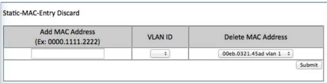
Figure 38: Deleting a MAC – Static-MAC-Entry Table
Port Mirroring
Port mirroring allows network traffic from one port to be copied or mirrored to another port. This is a very useful troubleshooting feature in that all data from one port is sent to another port which is attached to a computer or other network device that is configured to capture packets. This enables a network administrator or technician to see the traffic that is entering or leaving a particular port without disrupting normal network operations on the port that is being mirrored.
To navigate to the Port Mirroring menu:
- Click on the + next to Switching.
- Click on Port Mirroring.
To configure port mirroring for a port or ports (see Figure 39):
- Select the port or ports that traffic is to be mirrored from under the Mirror From column.
-
Select the destination port under the Mirror To drop down box.
-
Select the type of traffic that should be mirrored from the Mirror Mode drop down box. The available options are:
a. TX – transmit only
b. RX - Receive Only
c. TX/RX - Transmit and Receive.
- Click on the Submit button.
| Port Mirror Setup | ||
| Mirror From | Mirror To | Mirror Mode |
| ✓ fe1 ✓ fe2 □ fe3 □ fe4 □ fe5 □ fe6 □ fe7 □ fe8 □ fe9 □ fe10 □ ge1 □ ge2 | fe10 ▼ | Tx/Rx ▼ |
| Submit | ||
Figure 39: Port Mirroring
To disable port mirroring for a port or ports (see Figure 40):
1. Under the Current Settings section, the current port mirroring configuration should be displayed.
2. Click on the Delete button.
| Current Settings | ||
| Mirror From | Mirror To | Mirror Mode |
| fe1 fe2 | fe10 | both |
| Delete | ||
Figure 40: Disabling Port Mirroring
Link State Tracking
Link-state tracking binds the link state of multiple interfaces. Link-state tracking provides redundancy in the network when used with server network interface card (NIC) adapter teaming or bonding. When the server network adapters are configured in a primary or secondary relationship known as teaming and the link is lost on the primary interface, connectivity transparently changes to the secondary interface.
To navigate to the Link State Tracking menu:
- Click on the + next to Switching.
- Click on Link State Tracking.
Enable/Disable Link State Tracking
To enable Link State Tracking for a particular group (see Figure 41):
- Under Group Setting, click the check box of the Link State groups that are to be enabled (or disabled).
- Click on Update Setting.
| Group Setting | ||||||||||
| Group 1 | Group 2 | Group 3 | Group 4 | Group 5 | Group 6 | Group 7 | Group 8 | Group 9 | Group 10 | |
| Enable | ✔ | ✔ | □ | □ | □ | □ | □ | □ | □ | □ |
Figure 41: Link State Tracking
Port Settings
To configure individual ports for a Link State group (see Figure 42):
- Under Port Setting, select the Link State Group that the port will belong to from the Group drop down box
-
Select if the port is upstream or downstream from the Up/Down Stream)drop down box.
-
Click on Update Setting.
| Port Setting | |||
| Port | Group | (Up/Down)Stream | Status |
| fe1 | 1 ▼ | Up ▼ | |
| fe2 | 1 ▼ | Up ▼ | |
| fe3 | ▼ | Up ▼ | |
| fe4 | ▼ | Up ▼ | |
| fe5 | — | Up ▼ | |
Figure 42: Link State Tracking – Port Settings
PoE (Power over Ethernet) - System and Port Settings
This section only applies to Managed EtherWAN Switches with support for PoE.
To navigate to the PoE page:
- Click on the + next to Switching.
- Click on PoE.
PoE System Setting
The PoE Page provides access to PoE System Setting information and configuration. The information provided is (See Figure 43):
- Main Supply Voltage
- System Temperature
- Power Allocation – Actual wattage supplied to attached PoE device(s)
- System Power Budget – Configurable. The default value depends on the model of switch.
| PoE System Setting | |
| Main Supply Voltage | 47.00 (V) |
| System Temperature | 41.74 (C) |
| Power Allocation | 7.81 (W) |
| System Power Budget | 144.11 (W) |
| The value of 'System Power Budget' should greater than the sum of all port's 'Consumption' | |
| Submit | |
Figure 43: PoE System Setting
PoE Port Setting
The PoE Port Setting section provides the following configurable settings and information:
-
Enable Mode – Set the PoE Enable Mode by selecting one of the following settings in the drop-down box under PoE Mode (see Figure 44)
-
Enable – Enable PoE on a specific port
○ Disable – Disable PoE on a specific port -
Scheduling – Schedule time of day that PoE will be enabled per port
-
Power Limit by Classification – This setting tells the switch to negotiate with the attached PoE device to determine the Watts that will be provided by the switch. To change this setting, check (enable) or uncheck (disable) the check box located in the Power Limit by Classification column. The default is checked (Enabled). This is a per port setting (see Figure 44).
- Fixed Power Limit – Provides a fixed Wattage to the attached PoE (PD) device. This setting is only enabled after the Power Limit by Classification is disabled on a port and the Submit button is clicked.
- Power Priority – Use the Drop-Down box in the Power Priority column to set the priority to High, Medium or Low.
- Power Down Alarm – This setting only applies to EtherWAN Switches that have a relay. If this box is checked, losing PoE power on a port triggers the relay on the switch.
-
Status – Informational only. Provides the status of the PoE port
-
PD Class - Informational only. Provides the PoE Classification of the PoE (PD) device attached to the PoE port
-
Current (mA) – Informational only. Shows the current draw from the attached PoE (PD) device.
-
Consumption (W) - Informational only. Shows the power consumption of the attached PoE (PD) device.

NOTE: For EX78000-T series switches, all eight ports (Ports 1 - 8) can now port up to 30W PoE power. However, the total PoE power budget is still 181W.
| PoE Port Setting | |||||||||
| Port | Enable Mode | Power Limit by Classification | Fixed Power Limit (W) | Power Priority | Power Down Alarm | Status | PD Class | Current (mA) | Consumption (W) |
| fe1 | Enable | √ | 0.00 | High | ☐ | Delivering Power | PD Class 0 | 172.02 | 7.71 |
| fe2 | Enable | ☐ | 2.47 | Medium | ☐ | Delivering Power | PD Class 0 | 12.20 | 0.57 |
| fe3 | Enable | ☐ | 0.00 | Low | ☐ | Searching | N/A | 0 | 0 |
| fe4 | Enable | √ | 0.00 | Low | ☐ | Searching | N/A | 0 | 0 |
| fe5 | Enable | √ | 0.00 | High | ☐ | Searching | N/A | 0 | 0 |
| fe6 | Disable | √ | 0.00 | High | ☐ | Disable | N/A | 0 | 0 |
| fe7 | Scheduling | √ | 0.00 | High | ☐ | Disable | N/A | 0 | 0 |
| fe8 | Scheduling | √ | 0.00 | High | ☐ | Disable | N/A | 0 | 0 |
| Submit | |||||||||
Figure 44: PoE Port Setting
PoE Scheduling
PoE Scheduling allows PoE ports to have their power up time scheduled by hour of the day and day of the week. In order for a port to follow a schedule defined here, the port must be set to Scheduling on the PoE settings page (see PoE Port Setting)
To navigate to the PoE Scheduling page:
- Click on the + next to Switching.
- Click on PoE Scheduling.
Each PoE port on the switch can be schedule to power up and down automatically. To configure a port:
- Select the port from the drop-down list (See Figure 45)

Figure 45: Selecting a Port
- Select the hour(s) of day for each day of the week (see Figure 46).
- Click on the Submit button.

Figure 46: PoE Power Scheduling
PoE Watchdog
PoE Watchdog is a management feature to help system administrators monitor and manage critical PoE powered devices. PD Watchdog is only supported on PoE enabled ports. Once enabled, the system will continuously ping a user specified IP address across the port. If the
system does not receive a reply within a specified interval, it can automatically power down or power cycle the powered device.
To navigate to the PoE Watchdog page:
- Click on the + next to Switching.
- Click on PoE Watchdog.
To enable PoE Watchdog on a port, select enable from the drop-down menu, and then enter the IP address to which the device is connected. Set the ping interval and failure count, and choose the response action (No action, Power off PD, or Reboot PD). The StartUp Delay is the initial time delay before the system sends out the first ICMP echo request on the port (Range: 30 - 600 sec). Click Submit when finished.

Switch Configuration Examples Using CLI Commands
For more information on CLI command usage see CLI Command Usage.
Setting the Aging Time Value
To update the Aging Time value, use the CLI commands below:
CLI Command Mode: Global Configuration Mode
CLI Command Syntax: bridge 1 ageing-time (time in ms)
Usage Example:
switch_a>enable
switch_a#configure terminal
switch_a(config)#bridge 1 ageing time 300
switch_a(config)#q
switch_a#
Enabling Port Isolation
To enable Port Isolation for a port, use the CLI commands below:
CLI Command Mode: Interface Configuration Mode CLI Command Syntax: port-isolation enable port-isolation disable
Usage Example:
switch_a>enable
switch_a#configure terminal
switch_a(config)#interface fel
switch_a(config-if)#port-isolation enable
switch_a(config-if)#q
switch_a(config)#
Setting Storm Control
To set the value for the Broadcast and or DLF-Multicast Storm Control value of a port, use the CLI commands below:
CLI Command Mode: Interface Configuration Mode
CLI Command Syntax: stormcontrol
Usage Example:
switch_a>enable
switch_a#configure terminal
switch_a#configure interface fe1
switch_a(config-if)#storm-control broadcast 20
switch_a(config-if)#q
switch_a(config)#
Enabling Loopback Detect (Global)
To enable Loopback Detect, use the CLI commands below:
CLI Command Mode: Global Configuration Mode
CLI Command Syntax: bridge 1 loopback-detect
Usage Example:
switch_a>enable
switch_a#configure terminal
switch_a(config)#bridge 1 loopback-detect enable
switch_a(config)#q
switch_a#
Setting the Loopback Detect Action
To set the action for Loopback Detect, use the CLI commands below:
CLI Command Mode: Global Configuration Mode
CLI Command Syntax: bridge 1 loopback-detect action
Usage Example:
switch_a>enable
switch_a#configure terminal
switch_a(config)#bridge 1 loopback-detect action err-disable
switch_a(config)#q
switch_a#
Setting the Loopback Detect Recovery Time
To set the recovery time for Loopback Detect, use the CLI commands below:
CLI Command Mode: Global Configuration Mode
CLI Command Syntax: bridge 1 loopback-detect errdisable-recovery <0-65535>
Usage Example:
switch_a>enable
switch_a#configure terminal
switch_a(config)#bridge 1 loopback-detect errdisable-recovery 30
switch_a(config)#q
switch_a#
Setting the Loopback Detect Polling Interval
To set the polling interval for Loopback Detect, use the CLI commands below:
CLI Command Mode: Global Configuration Mode
CLI Command Syntax: bridge 1 loopback-detect interval <1-65535>
Usage Example:
switch_a>enable
switch_a#configure terminal
switch_a(config)#bridge 1 loopback-detect interval 5
switch_a(config)#q
switch_a#
Enabling Loopback Detect (Port)
To enable Loopback Detection, use the CLI commands below:
CLI Command Mode: Interface Configuration Mode
CLI Command Syntax: loopback-detect enable
Usage Example:
switch_a>enable
switch_a#configure terminal
switch_a#interface fe1
switch_a(config)# loopback-detect enable
switch_a(config)#q
switch_a#
Configuring Storm-Detect
To Enable or Disable Storm-Detect use the CLI command Below:
CLI Command Mode: Global Configuration Mode
CLI Command Syntax: bridge 1 storm-detect errdisable
no bridge 1 storm-detect errdisable
Default: Disabled
Usage Example – Enabling storm detect:
switch_a>enable
switch_a#configure terminal
switch_a(config)# bridge 1 storm-detect errdisable
switch_a(config)#q
switch_a#
Usage Example – Disabling storm detect:
switch_a>enable
switch_a#configure terminal
switch_a(config)# no bridge 1 storm-detect errdisable
switch_a(config)#q
switch_a#
To set the storm-detect interval use the following CLI commands:
CLI Command Mode: Global Configuration Mode
CLI Command Syntax: bridge 1 storm-detect interval <2-65535>
Default: 10
Usage Example:
switch_a>enable
switch_a#configure terminal
switch_a(config)# bridge 1 storm-detect interval 10
switch_a(config)#q
switch a#
To set the storm-detect recovery time use the following CLI commands:
CLI Command Mode: Global Configuration Mode
CLI Command Syntax: bridge 1 storm-detect errdisable-recovery <0-65535>
Default: 0 No errdisable recovery.
Usage Example:
switch_a>enable
switch_a#configure terminal
switch_a(config)# bridge 1 storm-detect errdisable-recovery 60
switch_a(config)#q
switch_a#
Storm Detect Packet Type
Enable this port's storm detect by detect number of broadcast or broadcast plus multicast packets per second. Unit is packets per second. Set to 0 to disable this feature.
To set the storm-detect packet type use the following CLI commands:
CLI Command Mode: Interface Configuration Mode
CLI Command Syntax: storm-detect (bc | mc-bc) pps <0-100000>
bc = broadcast only
mc-bc = count broadcast & multicast packets together.
Default: 0 (Disabled)
Usage Example 1 – Enabling Multicast + Broadcast:
switch_a>enable
switch_a#configure terminal
switch_a(config)# interface fel
switch_a(config-if)#storm-detect mc-bc pps 50000
switch_a(config-if)#q
switch_a(config)#q
switch_a#
Usage Example 2 – Enabling Multicast + Broadcast:
switch_a>enable
switch_a#configure terminal
switch_a(config)# interface fel
switch_a(config-if)#storm-detect bc pps 50000
switch_a(config-if)#q
switch_a(config)#q
switch_a#
To set the storm-detect utilization use the following CLI commands:
CLI Command Mode: Interface Configuration Mode
CLI Command Syntax: storm-detect utilization <0-100>
Default: 0 (Disabled)
Usage Example:
switch_a>enable
switch_a#configure terminal
switch_a(config)# interface fel
switch_a(config-if)#storm-detect utilization 80
switch_a(config-if)#q
switch_a(config)#q
switch_a#
To disable storm-detect on a port use the following CLI commands:
CLI Command Mode: Interface Configuration Mode
CLI Command Syntax: no storm-detect port enable
Usage Example:
switch_a>enable
switch_a#configure terminal
switch_a(config)# interface fel
switch_a(config-if)#no storm-detect port enable
switch_a(config-if)#q
switch_a(config)#q
switch_a#
To disable storm-detect on a port use the following CLI commands:
CLI Command Mode: Interface Configuration Mode
CLI Command Syntax: no storm-detect port enable
Usage Example:
switch_a>enable
switch_a#configure terminal
switch_a(config)# interface fel
switch_a(config-if)#no storm-detect port enable
switch_a(config-if)#q
switch_a(config)#q
switch_a#
Adding a MAC Address for Static-MAC-Entry Forwarding
To add a MAC address for Static-MAC-Entry Forwarding for a port, use the CLI commands below:
CLI Command Mode: Global Configuration Mode
CLI Command Syntax:
bridge 1 address
Usage Example:
switch_a>enable
switch_a#configure terminal
switch_a(config)# bridge 1 address 00e0.abcd.1245 forward fel vlan 1
switch_a(config)#q
switch_a#
Discard a Static MAC Entry
To discard a static MAC address, use the CLI commands below:
CLI Command Mode: Global Configuration Mode
CLI Command Syntax: bridge 1 address
Usage Example:
switch_a>enable
switch_a#configure terminal
switch_a(config)# bridge 1 address 00e0.abcd.1245 discard vlan 1
switch_a(config)#q
switch_a#
Configuring Port Mirroring
To configure a port for Port Mirroring, use the CLI commands below:
CLI Command Mode: Interface Configuration Mode
CLI Command Syntax: mirror interface
Usage Example:
switch_a>enable
switch_a#configure terminal
switch_a#interface gel
switch_a(config-if)# mirror interface fel direction both
switch_a(config-if)#q
switch_a(config)#q
switch_a#
Enabling a Link State Tracking Group
To enable a Link State Tracking Group, use the CLI commands below:
CLI Command Mode: Global Configuration Mode
CLI Command Syntax: link state track
Usage Example:
switch_a>enable
switch_a#configure terminal
switch_a(config)# link state track 4
switch_a(config)#q
switch_a#
Assigning a Port to a Link State Tracking Group
To assign a port to a Link State Tracking group, use the following CLI commands:
CLI Command Mode: Interface Configuration Mode
CLI Command Syntax: link state group
Usage Example:
switch_a>enable
switch_a#configure terminal
switch_a(config)#interface fel
switch_a(config-if)#link state group 4 downstream
switch_a(config-if)#q
switch_a(config)#q
switch_a#
Setting PoE Power Budget
To set the PoE Power Budget use the following CLI commands
CLI Command Mode: Global Configuration Mode
CLI Command Syntax: poe system-power-budget
Usage Example:
switch_a>enable
switch_a#configure terminal
switch_a(config)#poe system-power-budget 144.14
switch_a(config)#q
switch_a#
PoE Port Settings
The following commands are used to set PoE functions related directly to individual PoE ports:
| CLI Command (click link for syntax) | Function |
| Enable | Enables PoE on a port |
| fixed-power-limit | Sets a fixed wattage for a PoE port |
| Power-classification | Sets a port to negotiate power-classification |
| Power-down-alarm | Turns on alarm by relay on PoE power down |
| Power-priority | Sets priority of power distribution to ports |
| Scheduling | Enable Scheduling |
| Schedule-time | Sets schedule time to power PoE ports |
| Schedule-time-hour | Schedule time (hour) |
Enable
To enable or disable PoE on a port use the following CLI commands
CLI Command Mode: Interface Configuration Mode
CLI Command Syntax: poe enable no poe enable
Usage Example 1 – Enabling PoE on a port:
switch_a>enable
switch_a#configure terminal
switch_a(config)# interface fel
switch_a(config-if)# poe enable
switch_a(config-if)#q
switch_a(config)#q
Usage Example 2 – Disabling PoE on a port:
switch_a>enable
switch_a#configure terminal
switch_a(config)# interface fe1
switch_a(config-if)# no poe enable
switch_a(config-if)#q
switch_a(config)#q
fixed-power-limit
The fixed-power-limit CLI command sets the maximum wattage that a switch port will provide to the attached PoE device. To set a fixed power limit on a port Power Limit by Classification must be disabled on the port first (see Power-classification). To set the fixed-power-limit, use the following CLI command:
CLI Command Mode: Interface Configuration Mode
CLI Command Syntax: poe fixed-power-limit
Usage Example:
switch_a>enable
switch_a#configure terminal
switch_a(config)# interface fel
switch_a(config-if)# poe fixed-power-limit 7.5
switch_a(config-if)#q
switch_a(config)#q
Power-classification
This setting tells the switch to negotiate with the attached PoE device to determine the Watts that will be provided by the switch. To change this setting, check (enable) or uncheck (disable) the check box located in the Power Limit by Classification column. The default is checked (Enabled). This is a per port setting.
CLI Command Mode: Interface Configuration Mode
CLI Command Syntax: poe power-classification enable
no poe power-classification enable
Usage Example 1 – Enabling PoE Power Classification on a port:
switch_a>enable
switch_a#configure terminal
switch_a(config)# interface fel
switch_a(config-if)# poe power-classification enable
switch_a(config-if)#q
switch_a(config)#q
switch_a#
Usage Example 2 – Disabling PoE Power Classification on a port:
switch_a>enable
switch_a#configure terminal
switch_a(config)# interface fel
switch_a(config-if)# no poe power-classification enable
switch_a(config-if)#q
switch_a(config)#q
switch_a#
Power-down-alarm
This setting only applies to EtherWAN Switches that have a relay. If this setting is enabled, losing PoE power on a port triggers the relay on the switch.
To enable or disable the power down alarm, use the following CLI commands:
CLI Command Mode: Interface Configuration Mode
CLI Command Syntax:
poe power-down-alarm enable
no poe power-down-alarm enable
Usage Example 1 – Enabling PoE power down alarm on a port:
switch_a>enable
switch_a#configure terminal
switch_a(config)# interface fel
switch_a(config-if)# poe power-down-alarm enable
switch_a(config-if)#q
switch_a(config)#q
switch_a#
Usage Example 2 – Disabling PoE power down alarm on a port:
switch_a>enable
switch_a#configure terminal
switch_a(config)# interface fel
switch_a(config-if)# no poe power-down-alarm enable
switch_a(config-if)#q
switch_a(config)#q
switch_a#
Power-priority
Use this setting to set the priority to High, Medium or Low.
To set the PoE power priority, use the following CLI command:
CLI Command Mode: Interface Configuration Mode
CLI Command Syntax: poe power-priority
Usage Example:
switch_a>enable
switch_a#configure terminal
switch_a(config)# interface fel
switch_a(config-if)# poe power-priority medium
switch_a(config-if)#q
switch_a(config)#q
switch_a#
PoE Scheduling
PoE Scheduling allows PoE ports to have their power up time scheduled by hour of the day and day of the week.
Scheduling
To enable PoE Power Scheduling on a port, use the following CLI command:
CLI Command Mode: Interface Configuration Mode
CLI Command Syntax: poe scheduling enable
To disable PoE scheduling on a port use the no poe Enable command
Usage Example:
switch_a>enable
switch_a#configure terminal
switch_a(config)# interface fel
switch_a(config-if)# poe scheduling enable
switch_a(config-if)#q
switch_a(config)#q
switch_a#
Schedule-time
To enable PoE Power Scheduling on a port, use the following CLI command:
CLI Command Mode: Interface Configuration Mode
CLI Command Syntax: poe schedule-time
Day = 0 (Sunday) to 6 (Saturday)
Hour = 1 to 23. Multiple hours can be defined using a dash (ex. 1-23)
To disable PoE scheduling on a port use the no poe Enable command
Usage Example 1:
switch_a>enable
switch_a#configure terminal
switch_a(config)# interface fel
switch_a(config-if)# poe schedule-time 0 10
switch_a(config-if)#q
switch_a(config)#q
switch_a#
Usage Example 2 – Multiple hours:
switch_a>enable
switch_a#configure terminal
switch_a(config)# interface fel
switch_a(config-if)# poe schedule-time 0 10-14
switch_a(config-if)#q
switch_a(config)#q
switch_a#
Schedule-time-hour
To enable PoE Power Scheduling on a pse the following CLI command:
CLI Command Mode: Interface Configuration Mode
CLI Command Syntax: poe schedule-time
Day = 0 (Sunday) to 6 (Saturday)
Hour = 1 to 23
To disable PoE scheduling on a port use the no poe Enable command.
Usage Example:
switch_a>enable
switch_a#configure terminal
switch_a(config)# interface fe1
switch_a(config-if)# poe schedule-time 0 10
switch_a(config-if)#q
PoE Watchdog
To configure PoE Watchdog use the following CLI commands
CLI Command Mode: Interface Configuration Mode
CLI Command Syntax: poe watchdog check-address AAA.BBB.CCC.DDD poe watchdog enable
poe watchdog failure-action < noaction | powercycle |
poweroff >
poe watchdog failure-count <1-10>
poe watchdog ping-interval <30-600>
poe watchdog startup delay <30-600>
Usage Example:
switch_a>enable
switch_a#configure terminal
switch_a(config)#interface fel
switch_a(config-if)#poe watchdog enable
switch_a(config-if)#poe watchdog check-address 10.10.10.120
switch_a(config-if)#poe watchdog startup-delay 45
switch_a(config-if)#poe watchdog ping interval 60
switch_a(config-if)#poe watchdog failure-action <powercycle>
Extend PoE to 250 Meters
EX78900 only: PoE can be extended to 250m with 10Mbps transfer speed. When the extend mode is enabled, single POE port supports 250m transmission distances and 10Mbps speed.
CLI Command Mode: Interface Configuration Mode
CLI Command Syntax: [no] poe extend-mode enable
Note: It is suggested to pre-test the function before deployment. The maximum available transmission distance of PoE depends on the negotiation result of PD and PSE. Some PDs using EtherWAN PoE/PSE switches may only support a standard distance of 100 meters. Contact EtherWAN if assistance is needed.
TRUNKING
Overview
Port Trunking refers to the use of multiple network connections in parallel to increase the link speed beyond the limits of any one single cable or port. This is commonly called link aggregation. These aggregated links may be used to interconnect switches or to connect high-capacity servers to a network.
The managed switch supports up to six trunks for 100Mbps ports and up to two gigabit trunks. Each 100Mbps trunk can be composed of up to eight 100Mbps ports while each gigabit trunk can support up to four gigabit ports.
There are two popular types of port trunking, static and link aggregation control protocol (LACP). We will take a minute to discuss both types of trunking and why one would want to use them.
Static Channel Trunking
Originally specified in the IEEE802.3AD specification and now in the IEEE 802.1AX2008 specification, this type of trunking is the most basic and easiest to understand. It simply is the aggregation of two or more Ethernet links to form a virtual link equivalent in bandwidth to the sum of its individual links. For example, if one had four 100Mbps Ethernet links composing a single static channel, the overall bandwidth of the static channel would be 400Mbps.
The aggregation feature allows up to eight ports to be grouped together as a single-link connection between two switch devices. The increases the effective bandwidth thought a link and provides redundancy. It allows up to 6 aggregation groups on fast Ethernet interfaces and 2 aggregation groups on gigabit Ethernet interfaces, which depends on your available port counts. Ports within an aggregation group must be of the same linked speed. By performing a dynamic hashing algorithm on the MAC address, each packet destined for the aggregation is forwarded to one of the valid ports within the aggregation group. By dynamically performing this function, the traffic patterns can be more balanced across the ports within an aggregation. In addition, the MAC-based algorithm provides dynamic failover. If a port within an aggregation group fails, the other ports within the aggregation automatically assume all traffic designated for the aggregation.
Link Aggregation Control Protocol
Within the IEEE specification, the Link Aggregation Control Protocol (LACP) provides a method to control the bundling of several physical ports together to form a single logical channel. LACP allows a network device to negotiate an automatic bundling of links by sending LACP packets to the peer (directly connected device that also implements LACP). This means that both sides of the LACP channel must be configured for LACP which implies both devices must support it.
LACP also has a couple of very important advantages over static channel:
- Failover when a link fails and there is (for example) a media converter between the devices which means that the peer will not see the link down. With static link aggregation the peer would continue sending traffic down the link causing it to be lost.
- The device can confirm that the configuration at the other end can handle link aggregation. With Static link aggregation a cabling or configuration mistake could go undetected and cause undesirable network behavior.

NOTE: Before configuring a port trunk, disable or disconnect all of the ports that you use to use with this trunk. When the trunk has been (re)configured, enable or reconnect the port.
Port Trunking
To navigate to the Port Trunking menu:
- Click on the + next to Trunking.
- Click on Port Trunking.
There are 2 interfaces for Port Trunking supported, depending on the model of EtherWAN Managed switch.
Interface 1 (see Figure 47)
To create a trunk consisting of 100Mbps ports:
- Click on the checkbox for each desired port in the Static Channel Group or the LACP Group. A port cannot be in the Static Channel Group and the LACP Group at the same time
- Click on the Submit button.
To create a static trunk consisting of 1000Mbps ports:
- In the GE Trunking section, select Static or LACP.
- Click on the Submit button.
| Static Channel Group | ||||||||||||||||
| fe1 | fe2 | fe3 | fe4 | fe5 | fe6 | fe7 | fe8 | fe9 | fe10 | fe11 | fe12 | fe13 | fe14 | fe15 | fe16 | |
| Trunk 1 | ☐ | ☐ | ✓ | ✓ | ☐ | ☐ | ☐ | ☐ | ☐ | ☐ | ☐ | ☐ | ☐ | ☐ | ☐ | ☐ |
| LACP Group | ||||||||||||||||
| fe1 | fe2 | fe3 | fe4 | fe5 | fe6 | fe7 | fe8 | fe9 | fe10 | fe11 | fe12 | fe13 | fe14 | fe15 | fe16 | |
| Trunk 1 | ☐ | ☐ | ☐ | ☐ | ☐ | ☐ | ☐ | ☐ | ☐ | ☐ | ☐ | ☐ | ☐ | ☐ | ☐ | ☐ |
| GE Trunking | ||||||||||||||||
| Trunk 3 | ● Static ○ LACP ○ Disable | Submit | ||||||||||||||
| Note:4 ports maximum per trunk | ||||||||||||||||
Figure 47: Port Trunking – Interface 1
Version 2 (see Figure 48)
To create a static trunk consisting of 100Mbps ports:
- Click on the checkbox for each desired port in a particular trunk.
- Click on the Submit button.
To create a static trunk consisting of 1000Mbps ports (see Figure 48):
- In the GE Trunking section, click on the checkbox for each desired port in a particular trunk.
- Click on the Submit button.
| Static Channel Group | |||||||||||||||||||||||||||||||||||
| port 1 | port 2 | port 3 | port 4 | port 5 | port 6 | port 7 | port 8 | port 9 | port 10 | port 11 | port 12 | port 13 | port 14 | port 15 | port 16 | port 17 | port 18 | port 19 | port 20 | port 21 | port 22 | port 23 | port 24 | ||||||||||||
| Trunk 1 | ✓ | ✓ | ✓ | ☐ | ☐ | ☐ | ☐ | ☐ | ☐ | ☐ | ☐ | ☐ | ☐ | ☐ | ☐ | ☐ | ☐ | ☐ | ☐ | ☐ | ☐ | ☐ | ☐ | ||||||||||||
| Trunk 2 | ☐ | ☐ | ☐ | ✓ | ✓ | ✓ | ☐ | ☐ | ☐ | ☐ | ☐ | ☐ | ☐ | ☐ | ☐ | ☐ | ☐ | ☐ | ☐ | ☐ | ☐ | ☐ | ☐ | ||||||||||||
| Trunk 3 | ☐ | ☐ | ☐ | ☐ | ☐ | ☐ | ✓ | ✓ | ✓ | ☐ | ☐ | ☐ | ☐ | ☐ | ☐ | ☐ | ☐ | ☐ | ☐ | ☐ | ☐ | ☐ | ☐ | ||||||||||||
| Trunk 4 | ☐ | ☐ | ☐ | ☐ | ☐ | ☐ | ☐ | ☐ | ☐ | ✓ | ✓ | ✓ | ☐ | ☐ | ☐ | ☐ | ☐ | ☐ | ☐ | ☐ | ☐ | ☐ | ☐ | ||||||||||||
| Trunk 5 | ☐ | ☐ | ☐ | ☐ | ☐ | ☐ | ☐ | ☐ | ☐ | ☐ | ☐ | ☐ | ✓✓✓✓✓✓✓✓✓✓✓✓✓✓✓✓✓✓✓✓✓✓✓✓✓✓✓✓✓✓✓✓✓✓✓✓✓✓✓✓✓✓✓✓✓✓✓✓✓✓✓✓✓✓✓✓✓✓✓✓✓✓✓✓✓✓✓✓✓✓✓✓✓✓✓✓✓✓✓✓✓✓✓✓✓✓✓✓✓✓✓✓✓✓✓✓✓✓✓✓ ✓ ✓ ✓ ✓ ✓ ✓ ✓ ✓ ✓ ✓ ✓ ✓ ✓ ✓ ✓ ✓ ✓ ✓ ✓ ✓ ✓ ✓ ✓ ✓ ✓ ✓ ✓ ✓ ✓ ✓ ✓ ✓ ✓ ✓ ✓ ✓ ✓ ✓ ✓ ✓ ✓ ✓ ✓ ✓ ✓ ✓ ✓ ✓ ✓ ✓ ✓ ✓ ✓ ✓ ✓ ✓ ✓ ✓ ✓ ✓ ✓ ✓ ✓ ✓ ✓ ✓ ✓ ✓ ✓ ✓ ✓ ✓ ✓ ✓ ✓ ✓ ✓ ✓ ✓ ✓ ✓ ✓ ✓ ✓ ✓ ✓ ✓ ✓ ✓ ✓ ✓ ✓ ✓ ✓ ✓ ✓ ✓ ✓ ✓ ✓ √ √ √ √ √ √ √ √ √ √ √ √ √ √ √ √ √ √ √ √ √ √ √ √ √ √ √ √ √ √ √ √ √ √ √ √ √ √ √ √ √ √ √ √ √ √ √ √ √ √ ∞ √ √ √ √ √ √ √ √ √ √ √ √ √ √ √ √ √ √ √ √ √ √ √ √ √ √ √ √ √ √ √ √ √ √ √ √ √ √ √ √ √ √ √ √ √ √ √ √ √ ∶ √√√√√√√√√√√√√√√√√√√√√√√√√√√√√√√√√√√√√√√√√√√√√√√√√√√√√√√√√√√√√√√√√√√√√√√√√√√√√√√√√√√√√√√√√√√√√√√√√√√√√□ □ □ □ □ □ □ □ □ □ □ □ □ □ □ □ □ □ □ □ □ □ □ □ □ □ □ □ □ □ □ □ □ □ □ □ □ □ □ □ □ □ □ □ □ □ □ □ □ □ □ ▢ ▢ ▢ ▢ ▢ ▢ ▢ ▢ ▢ ▢ ▢ ▢ ▢ ▢ ▢ ▢ ▢ ▢ ▢ ▢ ▢ ▢ ▢ ▢ ▢ ▢ ▢ ▢ ▢ ▢ ▢ ▢ ▢ ▢ ▢ ▢ ▢ ▢ ▢ ▢ ▢ ▢ ▢ ▢ ▢ ▢ ▢ ▢ ▢ ▢ ▩□□□□□□□□□□□□□□□□□□□□□□□□□□□□□□□□□□□□□□□□□□□□□□□□□□□□□□□□□□□□□□□□□□□□□□□□□□□□□□□□□□□□□□□□□□□□□□□□□□□□○○○○○○○○○○○○○○○○○○○○○○○○○○○○○○○○○○○○○○○○○○○○○○○○○○○○○○○○○○○○○○○○○○○○○○○○○○○○○○○○○○○○○○○○○○○○○○○○○○○○ ○ ○ ○ ○ ○ ○ ○ ○ ○ ○ ○ ○ ○ ○ ○ ○ ○ ○ ○ ○ ○ ○ ○ ○ ○ ○ ○ ○ ○ ○ ○ ○ ○ ○ ○ ○ ○ ○ ○ ○ ○ ○ ○ ○ ○ ○ ○ ○ ○ ○ ○ ○ ○ ○ ○ ○ ○ ○ ○ ○ ○ ○ ○ ○ ○ ○ ○ ○ ○ ○ ○ ○ ○ ○ ○ ○ ○ ○ ○ ○ ○ ○ ○ ○ ○ ○ ○ ○ ○ ○ ○ ○ ○ ○ ○ ○ ○ ○ ○ ○ ● Note: 8 ports maximum per trunk Submit | ||||||||||||||||||||||
Figure 48: Port Trunking – Interface 2
LACP Trunking
To navigate to the LACP Trunking menu:
- Click on the + next to Trunking.
- Click on LACP Trunking.
There are 2 interfaces for Port Trunking supported, depending on the model of EtherWAN Managed switch.
Version 1 (see Figure 49)
To create a LACP trunk:
- In the Trunk Configuration section, select a port in the LACP trunk.
- Select LACP from the Trunk Type dropdown box for this port.
-
Enter an admin key for this port in the Admin Key textbox. 100Mbps ports admin keys must be 1 and 1Gbps ports must be 3.
-
Select the LACP Mode to either Active or Passive.
- Enter a value in the Port Priority textbox.
- Select a Timeout value of Short or Long.
- Click on the Submit button.
- Repeat steps 1-7 for each additional port that is to be used in the trunk.
To set the LACP System Priority
- Enter a value between 1 and 65535. The default value is 32768.
- Click on the Submit button.
| Port | Trunk Type | Admin Key | LACP Mode | LACP Port Priority | LACP Timeout | LACP Sync | LACP Sync Port | |
| fe1 | None | None | None | None | None | None | None | |
| fe2 | None | None | None | None | None | None | None | |
| fe3 | None | None | None | None | None | None | None | |
| fe4 | None | None | None | None | None | None | None | |
| fe5 | None | None | None | None | None | None | None | |
| fe6 | None | None | None | None | None | None | None | |
| fe7 | None | None | None | None | None | None | None | |
| fe8 | None | None | None | None | None | None | None | |
| fe9 | LACP | 1 | Active | None | Long | Not sync | NA | |
| fe10 | LACP | 1 | Active | None | Long | Not sync | NA | |
| ge1 | None | None | None | None | None | None | None | |
| ge2 | None | None | None | None | None | None | None | |
Figure 49: LACP Trunking Interface 1
Version 2 (see Figure 50)
To create a LACP trunk:
- In the Trunk Configuration section, select a port in the LACP trunk.
- Select LACP from the Trunk Type dropdown box for this port.
- Enter an admin key for this port in the Admin Key textbox. 100Mbps ports admin keys must be between 1-6 and 1Gbps ports must be between 7-8.
-
Select the LACP Mode to either Active or Passive.
-
Enter a value in the Port Priority textbox.
- Select a Timeout value of Short or Long.
-
Click on the Submit button.
-
Repeat steps 1-7 for each additional port that is to be used in the trunk.
| Port | Trunk Type | Admin Key | LACP Mode | LACP Port Priority | LACP Timeout | LACP Sync | LACP Sync Port |
| 1 | None | None | None | None | None | None | None |
| 2 | None | None | None | None | None | None | None |
| 3 | None | None | None | None | None | None | None |
| 4 | Static | 2 | None | None | None | None | None |
| 5 | Static | 2 | None | None | None | None | None |
| 6 | Static | 2 | None | None | None | None | None |
| 7 | Static | 3 | None | None | None | None | None |
| 8 | Static | 3 | None | None | None | None | None |
| 9 | Static | 3 | None | None | None | None | None |
| 10 | Static | 4 | None | None | None | None | None |
| 11 | Static | 4 | None | None | None | None | None |
| 12 | Static | 4 | None | None | None | None | None |
| 13 | Static | 5 | None | None | None | None | None |
| 14 | Static | 5 | None | None | None | None | None |
| 15 | Static | 5 | None | None | None | None | None |
| 16 | Static | 5 | None | None | None | None | None |
| 17 | Static | 5 | None | None | None | None | None |
| 18 | Static | 5 | None | None | None | None | None |
| 19 | Static | 6 | None | None | None | None | None |
| 20 | Static | 6 | None | None | None | None | None |
| 21 | Static | 6 | None | None | None | None | None |
| 22 | None | None | None | None | None | None | None |
| 23 | None | None | None | None | None | None | None |
| 24 | None | None | None | None | None | None | None |
| 25 | None | None | None | None | None | None | None |
| 26 | LACP | 7 | active | 1 | long | Not Sync | NA |
| 27 | None | None | None | None | None | None | None |
| 28 | LACP | 7 | active | 1 | long | Not Sync | NA |
| Port | Trunk Type | Admin Key (FE ports:1) (GE ports:3) | LACP Mode | LACP Port Priority (Set 0 for None) | LACP Timeout |
| fe1▼ | LACP▼ | 7 | Active▼ | 1 | Long▼ |
| Note: 4 ports maximum per trunkUpdate Setting | |||||
Figure 50: LACP Trunking – Interface 2
Trunking Configuration Examples Using CLI Commands
For more information on CLI command usage see CLI Command Usage.
Adding an Interface to a Static Trunk
To add an interface to a static trunk, use the CLI commands below:
CLI Command Mode: Interface Configuration Mode
CLI Command Syntax:
static-channel-group
Usage Example:
switch_a>enable
switch_a#configure terminal
switch_a(config)#interface fel
switch_a(config-if)#static-channel-group 1
switch_a(config-if)#q
switch_a(config)#q
switch_a#
Adding an Interface to a LACP Trunk
To add an interface to a LACP trunk, use the CLI commands below:
CLI Command Mode: Interface Configuration Mode
CLI Command Syntax:
channel-group
(LACP Channel is 1-6 for 100Mbps, 7-8 for 1Gbps ports)
Usage Example:
switch_a>enable
switch_a#configure terminal
switch_a(config)#interface fel
switch_a(config-if)# channel-group 2 mode passive
switch_a(config-if)#q
switch_a(config)#q
switch_a#
Setting the LACP Port Priority
To set the port priority for an interface attached to a LACP trunk, use the CLI commands below:
CLI Command Mode: Interface Configuration Mode
CLI Command Syntax: lacp port-priority <1 - 65535>
Usage Example:
switch_a>enable
switch_a#configure terminal
switch_a(config)#interface fe1
switch_a(config)# lacp port-priority 1
switch_a(config)#q
switch_a(config)#q
switch_a#
Setting the LACP Timeout
To set the timeout for an interface attached to a LACP trunk, use the CLI commands below:
CLI Command Mode: Interface Configuration Mode
CLI Command Syntax: lacp timeout
Usage Example:
switch_a>enable
switch_a#configure terminal
switch_a(config)#interface fe1
switch_a(config-if)# lacp timeout long
switch_a(config-if)#q
switch_a(config)#q
switch_a#
STP/RING PAGE – OVERVIEW
Choosing the Spanning Tree Protocols
The Spanning Tree algorithm works by designating a single switch (The Root Bridge) in the network, as the root or the parent to all the switches. All the switches in the network will use the same algorithm to form unique paths all the way back to the Root Bridge. Some switches establish a blocking point (a port on a switch) somewhere along the path to prevent a loop. There are 3 versions of the Spanning Tree protocol, STP, RSTP, MSTP, and they are all backwards compatible with each other.
Spanning Tree Protocol (STP)
This is the original Spanning Tree protocol, and it has been superseded by both the RSTP and MSTP protocol. It is based on a network with a maximum diameter of no more than 17 switches. It uses timers to synchronize any changes in the network topology, and this could take minutes. It is not recommended that you use this version of the Spanning Tree protocol.
Rapid Spanning Tree protocol (RSTP)
The RSTP protocol is the new enhanced version of the original STP protocol. It uses an enhanced negotiation mechanism to directly synchronize any topology changes between switches; it no longer uses timers as in the original STP protocol, which results in a faster re-convergence time. The maximum allowed network diameter for the RSTP protocol is 40 switches.
Multiple Spanning Tree Protocol (MSTP)
The MSTP protocol extends the RSTP protocol by simultaneously running multiple instances of the Spanning Tree Protocol and mapping different VLANs to each instance, thus providing load balance across multiple switches. The MSTP protocol accomplishes this by creating new extended sections within the RSTP protocol, called Regions. Each region runs its own instance of the Spanning Tree Protocol. Within each Region, the MSTP protocol can accommodate a network diameter of up to 40 switches. There can be a maximum of 40 Regions in a single MSTP network.

Note: If a faster recovery time is required, EtherWAN's proprietary Alpha-Ring ides a recovery time of <15MS with up to 250 switches. See STP/Ring Page - a Ring on page 162 for more information.
STP/RING PAGE - CONFIGURING RSTP
Global Configuration Page
To navigate to the STP/Ring Global Configuration page:
- Click on the + next to STP/Ring.
- Click on Global Configuration.
Enabling the RSTP Protocol
RSTP is enabled by Default. If RSTP has been disabled and you wish to enable it (see Figure 51):
- Click the dropdown box next to Spanning Tree Protocol and choose Enable.
- Click on the dropdown box next to STP Version and select RSTP.
- Click on the Update Setting button.
Additional Global Configuration page settings
- Bridge Priority – Bridge Priority is used to set the Root and backup Root Bridge. For more details see The Root Bridge & Backup Root Bridge.
○ Default is 32768. Range is 0 to 61440.
- Hello Time – This tells how often a BPDU (Bridge Protocol Data Unit) is sent (see Bridge Protocol Data Units). Default is 2 seconds. Range is 1 to 10 seconds.
- Max Age – Default is 20. Hop count limit for BPDU packets (see Setting the MAX Age, Forward Delay and Hello Timer),
• Forward Delay - Default is 15 sec.

Note: Bridge Protocol Data Units (BPDUs) are frames that contain information about the Spanning tree protocol (STP). Switches send BPDUs using a unique MAC address from its origin port and a multicast address as destination MAC (01:80:C2:00:00:00). There are three kinds of BPDUs:
- Configuration BPDU, used by Spanning Tree Protocol to provide information to all switches.
• TCN (Topology change), tells about changes in the topology. - TCA (Topology change Acknowledgment), confirm the reception of the TCN.
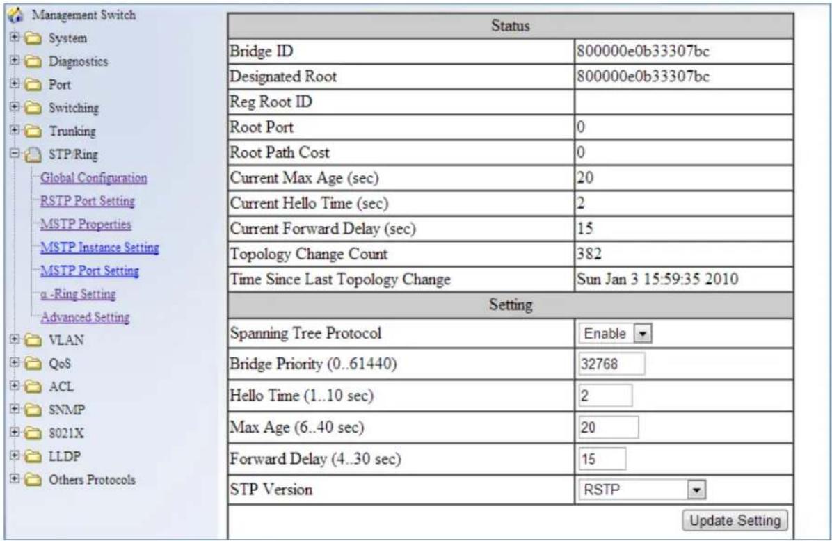
Figure 51: STP/Ring Global Configuration
The Root Bridge & Backup Root Bridge
To configure the Spanning Tree protocol on your network, you will need to setup a Root Bridge and Backup Root Bridge. In order to configure a switch to be the Root Bridge of a Spanning Tree network, you have to make sure that the Bridge Priority (which is the most significant 4 bits of the Bridge ID) of the switch is the lowest among any of the switches on the network. Similarly for the Backup Root Bridge, it must have the next lowest Bridge Priority of all the switches.

Note: Since the Bridge Priority is the most significant 4 bit of the Bridge ID, the lowest Bridge Priority will always be the Root Bridge and the second lowest Bridge Priority will be the Backup Root Bridge. If all switches have the same Bridge Priority, then The 12 bit System ID or MAC Address (if the system ID's are the same) will be used to determine the Root and Backup Root Bridge (See below).

Figure 52: Bridge ID
Bridge ID is a concatenation of 3 values: a 4 bit Bridge Priority (most significant), a 12 bit System ID (less significant), and the 48 bit MAC address of the local switch (least significant).
Setting the Root Bridge and Backup Root Bridge
To navigate to the STP/Ring Global Configuration page:
- Click on the + next to STP/Ring.
- Click on Global Configuration.
To set the Bridge Priority:
- Enter the Bridge Priority ID in the text box to the right of Bridge Priority (0..61440)
- Click on the Update Setting button.

Note: The valid values for this parameter are from 0 to 61440, in increments of
4096; you will see this value reflected in the first hexadecimal digit of the Bridge ID field after you click the Update Setting button (See Figure 53). Set this value to be less than any other switch on the network, in order to make this switch the Root Switch. To set a
Backup Root Bridge set the Bridge ID to be between the Root Bridge and the rest of the network switches.
| Status | |
| Bridge ID | 800000e0b33307bc |
| Designated Root | 800000e0b33307bc |
| Reg Root ID | |
| Root Port | 0 |
| Root Path Cost | 0 |
| Current Max Age (sec) | 20 |
| Current Hello Time (sec) | 2 |
| Current Forward Delay (sec) | 15 |
| Topology Change Count | 382 |
| Time Since Last Topology Change | Sun Jan 3 15:59:35 2010 |
Figure 53: Bridge ID Display
Setting the MAX Age, Forward Delay and Hello Timer
To navigate to the STP/Ring Global Configuration page:
- Click on the + next to STP/Ring.
- Click on Global Configuration.
The Network Diameter
The Diameter of a network depends on the type of topology your network uses. In a ring topology, the Network Diameter is the total number of switches in a network minus the Root Bridge. In a star topology, the Network Diameter is the maximum number of hops to get from Root Bridge to the switch that is the most hops away. In the RSTP protocol, the Max Age parameter is used as a hop count limit on how far the Spanning Tree protocol packet can propagate throughout the network topology, therefore, it must be configured with a value that is greater than the network diameter.
Relationship between Max Age, Forward Delay and Hello Time
The following rules must be followed when setting the Max Age, Forward Delay and Hello Timer:
• Max Age >= 2 × (Hello Time + 1.0 second)
- 2 × (Forward Delay - 1.0 second) >= Max Age
To change the Max Age, Forward Delay and Hello Timer (see Figure 54):
- Enter the Max Age in the text box to the right of Max Age (6..40 sec) label.
- Enter the Hello Time in the text box to the right of the Hello Time (1..10 sec) label.
- Enter the Forward Delay in the text box to the right of the Forward Delay (4..30 sec) label.
- Click on the Update Setting button.
- Save the configuration (see the Save Configuration Page)
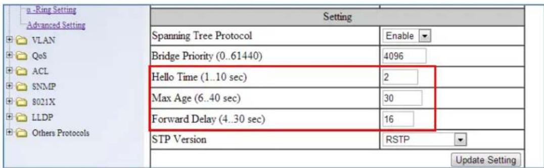
Figure 54: Max Age, Hello Timer & Forward Delay
RSTP Port Setting Page
To navigate to the STP/Ring RSTP Port Setting page:
- Click on the + next to STP/Ring.
- Click on RSTP Port Setting.
Spanning Tree Port Roles
In a stable RSTP topology, each port on a switch can function in any one of 4 different Spanning Tree port roles. These Spanning Tree port roles are (see Figure 55):
- Root Port
-
Designated Port
-
Alternate Port
- Backup Port
| Management Switch System Diagnostics Port Switching Trunking STP/Ring Global Configuration RSTP Port Setting MSITP Properties MSTP Instance Setting MSTP Port Setting a -Ring Setting Advanced Setting VLAN QoS ACL | 14 | Disabled(Discarding) | 128 | 200000 | Shared | Conf. Auto / Curr. Edge off |
| 15 | Disabled(Discarding) | 128 | 200000 | Shared | Conf. Auto / Curr. Edge off | |
| 16 | Disabled(Discarding) | 128 | 200000 | Shared | Conf. Auto / Curr. Edge off | |
| 17 | Disabled(Discarding) | 128 | 200000 | Shared | Conf. Auto / Curr. Edge off | |
| 18 | Disabled(Discarding) | 128 | 200000 | Shared | Conf. Auto / Curr. Edge off | |
| 19 | Disabled(Discarding) | 128 | 200000 | Shared | Conf. Auto / Curr. Edge off | |
| 20 | Disabled(Discarding) | 128 | 200000 | Shared | Conf. Auto / Curr. Edge off | |
| 21 | Disabled(Discarding) | 128 | 200000 | Shared | Conf. Auto / Curr. Edge off | |
| 22 | Disabled(Discarding) | 128 | 200000 | Shared | Conf. Auto / Curr. Edge off | |
| 23 | Disabled(Discarding) | 128 | 200000 | Shared | Conf. Auto / Curr. Edge off | |
| 24 | Disabled(Discarding) | 128 | 200000 | Shared | Conf. Auto / Curr. Edge off | |
| 25 | Rootport(Forwarding) | 128 | 200000 | Point to Point | Conf. Auto / Curr. Edge off | |
| 26 | Designated(Forwarding) | 128 | 20000 | Point to Point | Conf. Auto / Curr. Edge off | |
| 27 | Backup(Discarding) | 128 | 20000 | Point to Point | Conf. Auto / Curr. Edge off | |
| 28 | Alternate(Discarding) | 128 | 200000 | Point to Point | Conf. Auto / Curr. Edge off |
Figure 55: Spanning Tree Port Roles
Path Cost & Port Priority
By default, each port on a Spanning Tree switch will be assigned a Path Cost based on the port's transmission speed according to the IEEE standard below:
| Link speed | Recommended value |
| Less than or equal 100Kb/s | 200,000,000 |
| 1 Mb/s | 20,000,000 |
| 10 Mb/s | 2,000,000 |
| 100 Mb/s | 200,000 |
| 1 Gb/s | 20,000 |
| 10 Gb/s | 2,000 |
| 100 Gb/s | 200 |
| 1 Tb/s | 20 |
| 10 Tb/s | 2 |
By default each port on a Spanning Tree switch will be assigned a Port Priority of 128, according to the IEEE standard. This Port Priority is part of the Port ID, which is a concatenation of 2 values: Port Priority (4 bits) + Interface ID (12 bits) (see below)

Figure 56: Port ID
Port Priority is part of the Port ID, which is a concatenation of 2 values: Port Priority (4 bits) + Interface ID (12 bits).
The default values will work fine in most scenarios; however, there are times when you may need to adjust these values manually in order to influence the location of the Alternate Port, the Root Port or the Backup Port.
To adjust the Port Priority value or the Path Cost value on a port:
- Choose the correct port from the drop down list under Port (see below)
- Enter the proper value under the Priority (Granularity 16)
a. The Port Priority range is between 0 and 240 in multiples of 16.
- Enter the proper value under the Admin. Path Cost entry field.
a. The Path Cost range is between 1 and 200,000,000. - Click on the Update Setting button
- Save your configuration (see the Save Configuration Page).

Figure 57: Port Priority and Path Cost
Point to Point Link
By default, RSTP will assume any full-duplex link as a Point to Point Link, but if the switch detects that the neighbor switch is not running the RSTP protocol, it will assume the port to be a Shared Port. You can force a port to be a Shared Port, if you know in advance that there will be more than one switch connecting to this link (through an unmanaged switch, for example), or if you know in advance that the other switch on this link will be running the older STP protocol.
To manually force a port to be a Shared Port or a Point to Point Link:
- Choose the correct port from the drop down list under Port, and choose Enable or Disable under Point to Point Link (see Figure 57).
- Click on the Update Setting button.
- Save the configuration (see the Save Configuration Page)
Edge Port
By enabling the Edge Port feature on a port, the switch will stop reacting to any linkup event on this port, and will not send out any Topology Change notification to the neighbor bridges.
- Choose the correct port from the drop down list under Port, and choose Enable or Disable under Edge Port (see Figure 57).
- Click on the Update Setting button.
- Save the configuration (see the Save Configuration Page)
RSTP Configuration Examples Using CLI Commands
For more information on CLI command usage see CLI Command Usage.
Enabling the Spanning Tree Protocol
To enable the Spanning Tree function on a switch, use the following CLI commands:
CLI Command Mode: Global Configuration Mode
CLI Command Syntax:
no bridge shutdown 1
bridge 1 protocol rstp vlan-bridge
Usage Example:
switch_a>enable
switch_a#configure terminal
switch_a(config)#no bridge shutdown 1
switch_a(config)#bridge 1 protocol rstp vlan-bridge
switch_a(config)#q
switch_a#
Bridge Priority, Max Age, Forward Delay, and Hello Time
To configure the Bridge Priority, Max Age, Forward Delay, and Hello Time of a Spanning Tree Bridge, use the following CLI commands:
CLI Command Mode: Global Configuration Mode
CLI Command Syntax:
bridge 1 priority <0-61440>
bridge 1 max-age <6-40>
bridge 1 forward-time <4-30>
bridge 1 hello-time <1-10>
Usage Example:
switch_a>enable
switch_a#configure terminal
switch_a(config)#bridge 1 priority 4096
switch_a(config)#bridge 1 max-age 20
switch_a(config)#bridge 1 forward-time 15
switch_a(config)#bridge 1 hello-time 2
switch_a(config)#q
switch_a#
Modifying the Port Priority and Path Cost
To modify the Port Priority and Path Cost on a switch, use the below CLI commands:
CLI Command Mode: Interface Configuration Mode
CLI Command Syntax: bridge-group 1 path-cost <1-200000000> bridge-group 1 priority <0-240>
Usage Example:
switch_a>enable
switch_a#configure terminal
switch_a(config)#interface fel
switch_a(config-if)#bridge-group 1 path-cost 200000
switch_a(config-if)#bridge-group 1 priority 128
switch_a(config-if)#q
switch_a(config)#q
switch_a#
Manually Setting a Port to be a Shared or Point to Point Link
To manually force a port to be a shared link or Point-to-point link, use the below CLI commands:
CLI Command Mode: Interface Configuration Mode
CLI Command Syntax: spanning-tree link-type point-to-point spanning-tree link-type shared
Usage Example 1: Setting port 1 to be point-to-point:
switch_a>enable
switch_a#configure terminal
switch_a(config)#interface fe1
switch_a(config-if)#spanning-tree link-type point-to-point
switch_a(config-if)#q
switch_a(config)#q
switch_a#
Usage Example 2: Setting port 1 to be shared:
switch_a>enable
switch_a#configure terminal
switch_a(config)#interface fe1
switch_a(config-if)#spanning-tree link-type shared
switch_a(config-if)#q
switch_a(config)#q
switch_a#
Enabling/Disabling a port to be an Edge Port
To manually enable or disable a port to be an Edge Port, use the following CLI commands:
CLI Command Mode: Interface Configuration Mode
CLI Command Syntax: spanning-tree edgeport no spanning-tree edgeport
Usage Example 1: Enabling edge port on port 1:
switch_a>enable
switch_a#configure terminal
switch_a(config)#interface fel
switch_a(config-if)#spanning-tree edgeport
switch_a(config-if)#q
switch_a(config)#q
switch_a#
Usage Example 2: Disabling edge port on port 1:
switch_a>enable
switch_a#configure terminal
switch_a(config)#interface fe1
switch_a(config-if)#no spanning-tree edgeport
switch_a(config-if)#q
switch_a(config)#q switch_a#
STP/RING PAGE - CONFIGURING MSTP
The MSTP protocol adds a new concept called a Region to the Spanning Tree algorithm. Unlike RSTP and STP, inside each MSTP Region, there can be more than one instance of Spanning Tree Protocol running simultaneously. The MSTP protocol can then map multiple VLANs to each instance of Spanning Tree protocol to provide load balancing among the switches. Between Regions, the MSTP runs a single instance of Spanning Tree similar to, and is backward compatible with, the RSTP protocol.
Global Configuration Page
Enabling the MSTP Protocol
Navigate to the STP/Ring Global Configuration page:
- Click on the + next to STP/Ring.
- Click on Global Configuration.
- Verify that the Spanning Tree Protocol is enabled (see Figure 58), if not, choose Enabled from the Spanning Tree Protocol drop down list.
- Choose MSTP in the STP Version drop down list.
- Click on the Update Setting button.
- Save the configuration (see the Save Configuration Page).

Figure 58: Enabling MSTP
The CIST Root Bridge & Backup CIST Root Bridge
In order to configure a switch to be the CIST Root Bridge of a Spanning Tree network, you just have to make sure that the Bridge Priority (which is the most significant 4 bits of the Bridge ID) of the switch is the lowest among any of the switches on the network. Similarly for the Backup CIST Root Bridge, it must have the next lowest Bridge Priority of all the switches. This Bridge ID is a concatenation of 3 values: a 4 bit Bridge Priority (most significant), a 12 bit System ID (less significant), and the 48 bit MAC address of the local switch (least significant) (see below).

Figure 59: Bridge ID
Setting Bridge Priority
To set the Bridge Priority:
- Enter the Bridge Priority ID in the text box to the right of Bridge Priority (0..61440)
- Click on the Update Setting button.

Note: The valid values for this parameter are from 0 to 61440, in increments of 4096; you will see this value reflected in the first hexadecimal digit of the Bridge ID field after you click the Update Setting button (See Figure 60). Set this value to be less than any other switch on the network, in order to make this switch the Root Switch. To set a Backup Root Bridge set the Bridge ID to be between the Root Bridge and the rest of the network switches.

Figure 60: Bridge ID Display
Configuring the CST Network Diameter
When using MSTP, the Max Age parameter is used for the CST (Common Spanning Tree) topology simply as a hop count limit on how far the Spanning Tree protocol packet can propagate throughout the CST topology, therefore, the Max Age must be configured with a value that is greater than the network diameter of the CST topology. The Max Age parameter will need to be configured correctly on both the CIST Root Bridge as well as on the Backup CIST Root Bridge (in the event when the CIST Root Bridge fails).
Setting the MAX Age, Forward Delay and Hello Timer
Navigate to the STP/Ring Global Configuration page:
- Click on the + next to STP/Ring.
- Click on Global Configuration.
Relationship between Max Age, Forward Delay and Hello Time
The following rules must be followed when setting the Max Age, Forward Delay and Hello Timer:
- Max Age >= 2 × (Hello Time + 1.0 second)
- 2 × (Forward Delay - 1.0 second) >= Max Age
To change the Max Age, Forward Delay and Hello Timer (see Figure 61):
- Enter the Max Age in the text box to the right of Max Age (6..40 sec) label.
- Enter the Hello Time in the text box to the right of the Hello Time (1..10 sec) label.
- Enter the Forward Delay in the text box to the right of the Forward Delay (4..30 sec) label.
- Click on the Update Setting button.
- Save the configuration (see the Save Configuration Page)
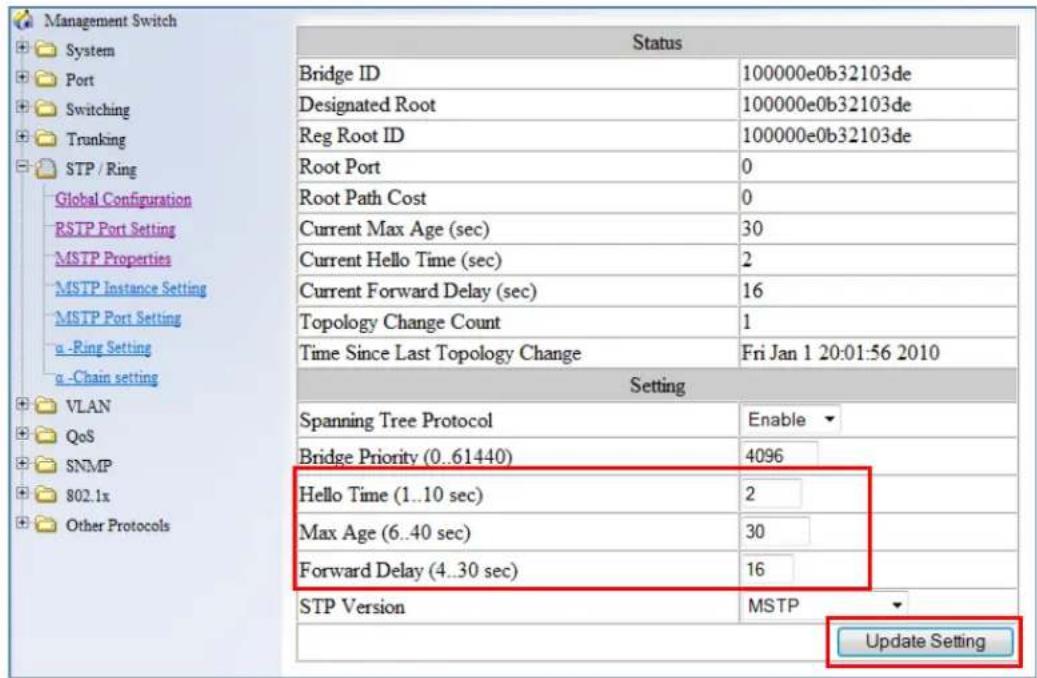
Figure 61: Max Age, Hello Timer & Forward Delay
MSTP Properties Page
Configuring an MSTP Region
In order to form a MSTP Region, the switches that will be connected together to form the MSTP Region must have the same values for the configuration parameters listed below. Two of the parameters can be configured directly, the third parameter (Configuration Digest) will be automatically calculated by the switch based on the VLAN to MSTI (Multiple Spanning Tree Instance) mapping. The VLAN to MSTI instance mapping must be the same for all the switches within the same MSTP Region (see MSTP Instance Setting Page).
- Region name
- Revision level
- Configuration Digest
To navigate to the STP/Ring MSTP Properties page:
- Click on the + next to STP/Ring.
- Click on MSTP Properties.
To configure both the MSTP Regional Configuration Name and the Revision Level for each of the switches located in the same MSTP Region (see below):
- Enter the Region Name of the Region that the switch will belong to in the Region Name entry field,
- Enter the Revision Level value for the corresponding Region in the Revision Level entry field,
- Click on the Update Setting button.
- Save the configuration (see the Save Configuration Page)
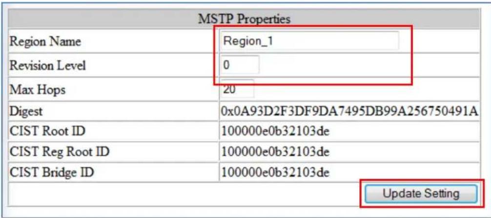
Figure 62: MSTP Region and Revision Level
Configuring the IST Network Diameter
To navigate to the STP/Ring MSTP Properties page:
- Click on the + next to STP/Ring.
- Click on MSTP Properties.
In the MSTP protocol, the Max Hops parameter is used for the IST (Internal Spanning Tree) and the MSTI (Multiple Spanning Tree Instance) topology as a hop count limit on how far the Spanning Tree protocol packet can propagate inside of a MSTP Region, therefore, it must be configured with a value that is greater than the network diameter of the IST/MSTI topology. The Max Hops parameters should be configured correctly on the CIST Root and
the Backup CIST Root switch and on all of the Boundary switches of a MSTP Region (if there are multiple Regions within your MSTP network).
Follow the steps below to configure the Max Hops parameter:
- Enter the desired hop count in the entry field next to Max Hops
- Click on the Update Setting button (see below).
- Save the configuration (see the Save Configuration Page)

Figure 63: MSTP Properties – Max Hops
MSTP Instance Setting Page
Setting an MSTP Instance
Navigate to the STP/Ring MSTP Instance Setting page:
- Click on the + next to STP/Ring.
- Click on MSTP Instance Setting.
To create the Spanning Tree instances to be run inside a MSTP Region and its VLAN mappings, follow the below steps.
- Click on the VLAN Instance Configuration button (see Figure 64),
- Choose the VLAN that you want to map to a MSTI instance from the VLAN ID drop down box (see Figure 65).
- Enter the Instance ID that you want the VLAN to map to In the entry field next to Instance ID (1..15).
- Click on the Update Settings button.
- Save the configuration (see the Save Configuration Page)

Note: You can enter a new instance number here, which is how a new MSTI instance is created. You can use an existing MSTI instance if it has already been created on another switch.

Figure 64: VLAN Instance Configuration

Figure 65: VLAN Instance ID
Modifying MSTP parameters for load balancing
To navigate to the STP/Ring MSTP Instance Setting page:
- Click on the + next to STP/Ring.
- Click on MSTP Instance Setting.
To load balance switches within a MSTP Region, set different switches within the MSTP Region to be the Root Bridge for different MSTI instances. A Root Bridge in a particular MSTI instance is called a MSTI Regional Root Bridge.
To designate a specific switch in a MSTP Region to be the Root Bridge in a specific MSTI instance, the bridge priority must be set to be the lowest number of all the switches in a particular MSTI instance.
To set the bridge priority on the switch for a specific MSTI Instance (see Figure 66):
- Choose the particular instance in the Instance ID drop down list for which the switch will be a MSTI Regional Root Bridge;
- Enter the desired value in the Bridge Priority text box
- Click on the Update Setting button. The valid values for this parameter are from 0 to 61440, in increments of 4096.
- Save the configuration (see the Save Configuration Page)

Figure 66: Setting the MSTI Regional Root Bridge
MSTP Port Setting page
Adjusting the blocking port in a MSTP network
To navigate to the STP/Ring MSTP Port Setting page:
- Click on the + next to STP/Ring.
- Click on MSTP Port Setting.
You can adjust the location of the blocking port in a MSTP network by modifying the Port Priority and the Path Cost of the ports on the switch. Modifying the Port Priority adjusts the blocking port between two switches. Modify the Port Cost adjusts the location of the blocking port in a MSTP loop.
To modify the Port Priority and the Path Cost of the ports on a MSTP switch for the MSTI instance only, follow these steps:
- Choose the correct MSTI Spanning Tree instance from the drop down list under Instance ID (see Figure 67).
- Choose the correct port number from the drop down list under Port, and enter the proper value under the Priority and the Admin. Path Cost text box,
- Click on the Update Setting button (see Figure 67).
- Save the configuration (see the Save Configuration Page)

Figure 67: Port Cost & Priority
MSTI Instance Port Membership
To navigate to the STP/Ring MSTP Port Settings page:
- Click on the + next to STP/Ring.
- Click on MSTP Port Setting.
If changes have been made to the port membership of a VLAN, you must also reconfigure the MSTI port membership for the MSTI instance that the VLAN maps to.
To reconfigure the MSTI instance port membership:
- Click on the Port Instance Configuration button (see Figure 68)
- Choose the correct MSTI instance from the drop down list next to Instance ID (see Figure 69).
- Check the box next to all the ports that should be part of this instance
- Click on the Update Setting button.
- Save the configuration (see the Save Configuration Page)
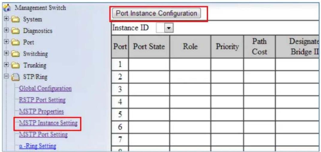
Figure 68: Port Instance Configuration

Figure 69: Port Instance - Adding Ports
MSTP Configuration Examples Using CLI Commands
For more information on CLI command usage see CLI Command Usage.
Enabling Spanning Tree for MSTP
To enable the Spanning Tree function on a switch use the below CLI commands.:
CLI Command Mode: Global Configuration Mode
CLI Command Syntax:
no bridge shutdown 1
bridge 1 protocol mstp
Usage Example:
switch_a>enable
switch_a#configure terminal
switch_a(config)#no bridge shutdown 1
switch_a(config)#bridge 1 protocol mstp
switch_a(config)#q
switch_a#
Bridge Priority, Max Age, Forward Delay, and Hello Time
To configure the CIST Bridge Priority, Max Age, Forward Delay, and Hello Time of a Spanning Tree Bridge, use the following CLI commands:
CLI Command Mode: Global Configuration Mode
CLI Command Syntax:
bridge 1 priority <0-61440>
bridge 1 max-age <6-40>
bridge 1 forward-time <4-30>
bridge 1 hello-time <1-10>
Usage Example:
switch_a>enable
switch_a#configure terminal
switch_a(config)#bridge 1 priority 4096
switch_a(config)#bridge 1 max-age 20
switch_a(config)#bridge 1 forward-time 15
switch_a(config)#bridge 1 hello-time 2
switch_a(config)#q
switch_a#
IST MAX Hops
To configure the IST Max Hops parameter on a switch, use the following CLI commands:
CLI Command Mode: Global Configuration Mode
CLI Command Syntax: bridge 1 max-hops <1-40>
Usage Example:
switch_a>enable
switch_a#configure terminal
switch_a(config)#bridge 1 max-hops 20
switch_a(config)#q
switch_a#
MSTP Regional Configuration Name and the Revision Level
To configure both the MSTP Regional Configuration Name and the Revision Level on a switch, use the following CLI commands:
CLI Command Mode: MSTP Configuration Mode
CLI Command Syntax:
bridge 1 region
Usage Example:
switch_a>enable
switch_a#configure terminal
switch_a(config)#spanning-tree mst configuration
switch_a(config-mst)#bridge 1 region R1
switch_a(config-mst)#bridge 1 revision 0
switch_a(config-mst)#q
switch_a(config)#q
switch_a#
Creating an MSTI Instance
To create a MSTI instance and map it to a VLAN, use the following CLI commands:
CLI Command Mode: MSTP Configuration Mode
CLI Command Syntax: bridge 1 instance <1-15> vlan
Usage Example:
switch_a>enable
switch_a#configure terminal
switch_a(config)#spanning-tree mst configuration
switch_a(config-mst)#bridge 1 instance 1 vlan 10
switch_a(config-mst)#q
switch_a(config)#q
switch_a#
Setting MSTI Priority
To set the MSTI priority of a switch in a MSTP Region, use the following CLI commands:
CLI Command Mode: Global Configuration Mode
CLI Command Syntax: bridge 1 instance <1-15> priority <0-61440>
Usage Example:
switch_a>enable
switch_a#configure terminal
switch_a(config)#bridge 1 instance 1 priority 0
switch_a(config)#q
switch_a#
Modifying CIST Port Priority and Port Path Cost
To modify the CIST Port Priority and CIST Port Path Cost on a switch, use the below CLI commands:
CLI Command Mode: Interface Configuration Mode (port)
CLI Command Syntax: bridge-group 1 path-cost <1-200000000>; bridge-group 1 priority <0-240>
Usage Example:
switch_a>enable
switch_a#configure terminal
switch_a(config)#interface fel
switch_a(config-if)#bridge-group 1 path-cost 200000
switch_a(config-if)#bridge-group 1 priority 128
switch_a(config-if)#q
switch_a(config)#q
switch_a#
To modify the MSTI Port Priority and MSTI Port Path Cost for an Instance on a switch, use the below CLI commands:
CLI Command Mode: Interface Configuration Mode
CLI Command Syntax: bridge-group 1 instance <1-15> path-cost <1-200000000> bridge-group 1 instance <1-15> priority <0-240>
Usage Example:
switch_a>enable
switch_a#configure terminal
switch_a(config)#interface fe1
switch_a(config-if)#bridge-group 1 instance 1 path-cost 20000
switch_a(config-if)#bridge-group 1 instance 1 priority 128
switch_a(config-if)#q
switch_a(config)#q
switch_a#
Adding a Port to an MSTI Instance
To add a port to a MSTI instance (this port must be a member port of the VLAN that is mapped to the MSTI instance), use these CLI commands:
CLI Command Mode: Interface Configuration Mode
CLI Command Syntax: bridge-group 1 instance <1-15>
Usage Example:
switch_a>enable
switch_a#configure terminal
switch_a(config)#interface fe1
switch_a(config-if)#bridge-group 1 instance 1
switch_a(config-if)#q
switch_a(config)#q
switch_a#
STP/RING PAGE - ALPHA RING
Alpha Ring Setting Page
To navigate to the STP/Ring Alpha-Ring Settings page:
- Click on the + next to STP/Ring.
- Click on Alpha-Ring Setting.
EtherWAN Alpha-Ring Technology
The Alpha-Ring protocol was designed and developed by EtherWAN to overcome traditional STP and RSTP's inability to provide fast network recovery and minimize packet loss caused by link failure. Among the advantages of Alpha-Ring are:
• High-speed Recovery – Less than 15 milliseconds
- Flexibility for Network Deployment – Coexistence with STP, RSTP and MSTP
- Ring Coupling – Smaller rings coupled together through a single switch to increase network efficiency
Implementing a Simple Alpha-Ring
- Change the Ring State to Enabled
- Click on the Update Setting button.
Next, the ports that will be used to connect this switch to the Alpha-Ring need to be assigned to provide the connection redundancy (see Figure 70).
- Change Ring Port 1 to the port you will be using for the first ring connection
- Change Ring Port 2 to the port you will be using for the second ring connection.
- Click on the Update Setting button.
- Save the configuration (see the Save Configuration Page)
| Ring State | Enable✓ | Update Setting | |
| Ring V2 State | Disable✓ | ||
| Defined Block State | Disable✓ | ||
| Restore-Block (4..300 sec) | 4 | ||
| Update Setting | |||
| Set Ring Port | Ring Port 1 fe1✓ | Ring Port 2 fe2✓ | |
| Ring Port State | FORWARD | DOWN | |
| Block Port | Port1○ | Port2○ | |
| Update Setting | |||
Figure 70: Alpha-Ring Settings
Alpha-Ring V2
The Alpha-ring protocol will automatically set the last connected link to BLOCK status. However, sometimes you may need to keep a specific link in a FOWARD state. An example would be where a port was connected to a high capacity fiber link – overall network performance would benefit by keeping that link running. Alpha-ring V2 allows you to manually define the port in the ring topology that will be set to BLOCK state. If a link in the ring fails, the pre-defined blocked port will be set to a forward state in less than 15 milliseconds. When the failed link is restored, the pre-defined block port will return to a BLOCK state in the time defined by the Restore-Block variable.
To pre-define the block port (See Figure 69):
- Set the Ring V2 State to Enable.
- Set the Defined Block State to Enable.
- Enter Restore-Block time in seconds.
-
Click Update Setting
-
Select the Ring port that you want to block by clicking the radio button underneath that port. Then click the corresponding Update Setting button.
The Alpha-Ring V2 protocol must be enabled on all switches in ring. However, the Defined Block State should only be enabled on the switch that has the port you want to set as blocked.
| Ring V2 State | Enable✓ | |
| Defined Block State | Enable✓ | |
| Restore-Block (4..300 sec) | 4 | |
| Update Setting | ||
| Set Ring Port | Ring Port 1 fe1✓ | Ring Port 2 fe10✓ |
| Ring Port State | FORWARD | FORWARD |
| Block Port | Port1● | Port2○ |
| Update Setting | ||
Figure 71: Pre-defining a Block Port with Alpha-Ring V2 Settings
Connecting two Alpha-Ring Networks together (Ring Coupling)
To navigate to the STP/Ring Alpha-Ring Settings page:
- Click on the + next to STP/Ring.
- Click on Alpha-Ring Setting.
As additional switches are added to a network, it may become necessary to connect multiple Alpha-Ring networks together. This is called Ring-coupling and uses two additional Ethernet ports on the switch. To setup Ring-coupling (see Figure 73):
- Change the Ring-coupling state to Enable or Neighbor Only (If Neighbor Only is selected, control frames will be sent on Alpha Ring port only, and not on the coupling port).
- Click on the Update Setting button next to the Ring-coupling state.
- Choose the desired port from the dropdown list under Ring Coupling Port 1
- Choose the desired port from the dropdown list under Ring Coupling Port 2
- Click on the Update Setting button.
- Save the configuration (see the Save Configuration Page)

flowchart
graph TD
    A["Device 1"] -->|Ring Port| B["Device 2"]
    B -->|Ring Port| C["Device 3"]
    C -->|Coupling port| D["Device 4"]
    D -->|Coupling port| E["Device 5"]
    E -->|Ring Port| A
    style A fill:#f9f,stroke:#333
    style B fill:#ccf,stroke:#333
    style C fill:#cfc,stroke:#333
    style D fill:#fcc,stroke:#333
    style E fill:#cff,stroke:#333
Figure 72: Ring Coupling Example
| Ring Coupling State | Disable▼ | Update Setting | ||
| Set Coupling Port | Disable Enable Neighbor Only | Coupling Port 2 fe4▼ | ||
| Port State | DOWN | DOWN | ||
| Update Setting | ||||
Figure 73: Ring Coupling
Connecting Additional Rings (Redundancy Pairs)
Only two rings can be connected through Ring Coupling. To connect additional rings, you will need to use Redundant Port Pairs. Below are some topology examples for using redundancy pairs to connect two or more rings.

flowchart
graph TD
    A["Router 01"] -->|Redundant Pair ID=10 (Primary Path)| B["Router 02"]
    B -->|Redundant Pair ID=10 (Backup Path)| A
    A --> C["Router 01"]
    B --> D["Router 02"]
    C --> E["Router 01"]
    D --> F["Router 02"]
Figure 74: Redundant Pair Example 1

flowchart
graph TD
    A["Router 01"] -->|Primary Path (Backup Path)| B["Router 02"]
    B -->|Redundant Pair ID=10| A
    A --> C["Router 01"]
    B --> D["Router 02"]
    C --> A
    D --> B
Figure 75: Redundant Pair Example 2
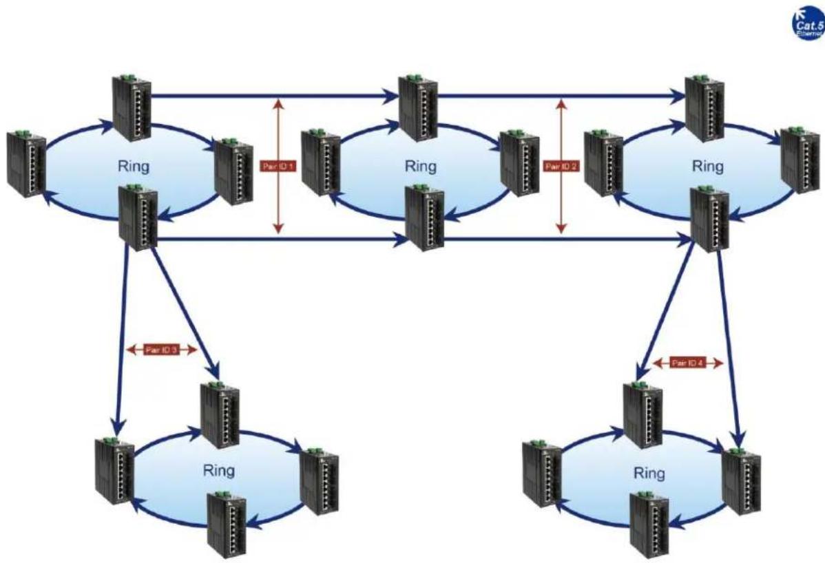
flowchart
graph TD
    A["Node 1"] --> B["Ring"]
    B --> C["Node 2"]
    C --> D["Ring"]
    D --> E["Node 3"]
    E --> F["Ring"]
    F --> G["Node 4"]
    G --> H["Ring"]
    H --> I["Node 5"]
    I --> J["Ring"]
    J --> K["Node 6"]
    K --> L["Ring"]
    L --> M["Node 7"]
    M --> N["Ring"]
    N --> O["Node 8"]
    O --> P["Ring"]
    P --> Q["Node 9"]
    Q --> R["Ring"]
    R --> S["Node 10"]
    S --> T["Ring"]
    T --> U["Node 11"]
    U --> V["Ring"]
    V --> W["Node 12"]
    W --> X["Ring"]
    X --> Y["Node 13"]
    Y --> Z["Ring"]
    Z --> A
    style A fill:#f9f,stroke:#333
    style B fill:#ccf,stroke:#333
    style C fill:#ccf,stroke:#333
    style D fill:#ccf,stroke:#333
    style E fill:#ccf,stroke:#333
    style F fill:#ccf,stroke:#333
    style G fill:#ccf,stroke:#333
    style H fill:#ccf,stroke:#333
    style I fill:#ccf,stroke:#333
    style J fill:#ccf,stroke:#333
    style K fill:#ccf,stroke:#333
    style L fill:#ccf,stroke:#333
    style M fill:#ccf,stroke:#333
    style N fill:#ccf,stroke:#333
    style O fill:#ccf,stroke:#333
    style P fill:#ccf,stroke:#333
    style Q fill:#ccf,stroke:#333
    style R fill:#ccf,stroke:#333
    style S fill:#ccf,stroke:#333
    style T fill:#ccf,stroke:#333
Figure 76 Redundant Pair Example 3
To setup Redundant Pairs:
- Change the Redundancy State to Enable.
- Click on the Update Setting button next to the Redundancy State
- Select the port that will act as a Redundant Port, and choose "Normal" or "Slave" with the radio buttons. ("Normal" means "Master" in this context.)
- Choose a Pair ID for the port.
- Click on the Update Setting button.
To delete an existing Redundant Port, select it by clicking the check box at the right and then clicking Update Setting.

Figure 77: Redundancy Pairs Configuration
Configuring Alpha Ring using CLI commands
For more information on CLI command usage see CLI Command Usage.
Enable Alpha Ring and Alpha Ring V2 Protocols
To enable the Alpha Ring and Alpha Ring V2 protocols, use the following CLI commands:
CLI Command Mode: Global Configuration Mode
CLI Command Syntax: bridge 1 ring enable/disable
(no) ring v2 enable
Usage Example 1: Enabling alpha ring
switch_a>enable
switch_a#configure terminal
switch_a(config)# bridge 1 ring enable
switch_a(config)#q
switch_a#
Usage Example 2: Enabling alpha V2 ring
switch_a>enable
switch_a#configure terminal
switch_a(config)# ring v2 enable
switch_a(config)#q
switch_a#
Set the Ring Ports
To configure the ports used in the ring, use the following CLI commands:
CLI Command Mode: Global Configuration Mode
CLI Command Syntax: ring set-port
(interface1 and interface2 will be set as ring-port 1 and ring-port 2)
Usage Example 1:
switch_a>enable
switch_a#configure terminal
switch_a(config)# ring set-port fe2 fe3
switch_a(config)#q
switch_a#
Show Ring, Port and All States
There are three CLI commands for viewing Alpha Ring statuses:
CLI Command Mode: Privileged Exec Mode
CLI Commands: show ring state -- Shows ring service state as enable or disabled.
show ring port-state -- Shows whether ring ports are in BLOCK or FORWARD mode.
show ring all -- Shows all Alpha and Alpha Ring V2 information.
Usage Example 1:
switch_a>enable
switch_a#show ring state
switch_a(config)#
ring enable
switch_a(config)#show ring port-state
ring-port 1 fe2 BLOCK
ring-port 2 fe3 FORWARD
switch_a#show ring all
Ring protocol: Enable
Ring frame type V2: Enable
Ring Defined-Block state: Enable
Ring Restore-Block seconds: 4
Ring coupling protocol: Disable
Port Interface
State
| Ring port 1 | fe2 | defined-block | Block |
| Ring port 2 | fe3 | Forward | |
| Coupling port 1 | fe3 | Forward | |
| Coupling port 2 | fe4 | Down |
Define a Ring's Blocked Port
To define a specific port to be set to BLOCK state, use the following CLI commands:
CLI Command Mode: Global Configuration Mode
CLI Command Syntax: ring set-defined-block <1-2>
Usage Example 1:
switch_a>enable
switch_a#configure terminal
switch_a(config)# ring set-defined-block 1
switch_a(config)#q
switch_a#
Set Delay Time for Restoration of a Failed Port
To set the delay in seconds for the restoration of a failed port, use the following CLI commands:
CLI Command Mode: Global Configuration Mode
CLI Command Syntax: ring restore-block <4-300>
Enable Ring Coupling
To enable the ring to be coupled to another ring, use the following CLI commands:
CLI Command Mode: Global Configuration Mode
CLI Command Syntax: (no) ring-coupling enable
Usage Example 1:
switch_a>enable
switch_a#configure terminal
switch_a(config)# ring-coupling enable
switch_a(config)#q
switch_a#
Set Ring Coupling Ports
To define the ports that will be used for ring coupling, use the following CLI commands:
CLI Command Mode: Global Configuration Mode
CLI Command Syntax: ring set-coupling-port
Usage Example 1: Set ports fe7 and fe8 as coupling ports for connection to another ring
switch_a>enable
switch_a#configure terminal
switch_a(config)# ring set-coupling-port fe7 fe8
switch_a(config)#q
switch_a#
Enable Redundancy Pairs
To enable the ring to be coupled to another ring using redundant port pairs, use the following CLI commands:
CLI Command Mode: Privileged Exec Mode
CLI Command Syntax: (no) redundancy pair enable
Usage Example:
switch_a>enable
switch_a#configure terminal
switch_a(config)# redundancy pair enable
switch_a(config)#q
switch_a#
Configure Redundancy Pairs
To set the redundancy pair normal (master) ID, the slave ID, or to make a port no longer part of a redundant pair, use the following CLI commands:
CLI Command Mode: Interface Configuration mode
CLI Command Syntax: redundancy pair id <1-253> redundancy pair slave id <1-253> no redundancy pair
Usage Example: Set port fe7 as a normal (master) redundancy port, with an ID of 100.
switch_a>enable
switch_a#configure terminal
switch_a(config)#interface fe7
switch_a(config-if)#redundancy pair id 100
switch_a(config-if)#q
Show Ring Coupling, Port Coupling, and Redundancy Pair States
To view the statuses of ring couplings and rings connected by redundancy pair, use the following CLI commands:
CLI Command Mode: Privileged Exec Mode
CLI Command Syntax: show ring-coupling state
CLI Command Syntax: show ring-coupling port-state
CLI Command Syntax: show redundancy pair
CLI Command Syntax: show redundancy pair <interface>
Usage Example 1:
switch_a>enable
switch_a# show ring-coupling state
ring-coupling enable
switch_a(config)# show ring-coupling port-state
ring-coupling-port 1 fe7 DOWN
ring-coupling-port 2 fe8 DOWN
switch_a(config)#q
switch_a#
STP/RING PAGE – ALPHA CHAIN
The Alpha Chain Protocol
Although the Spanning Tree Protocols are very versatile in forming all possible redundant topologies, its re-convergence time is too slow for most mission critical applications. The EtherWAN Alpha Ring protocols can be used in mission critical applications to recover from a link failure in 15 milliseconds or less. However, with the Alpha Ring protocols (Alpha Ring, Alpha Ring-Coupling), the redundant topologies that these protocols can be applied to will be limited to at the most two Rings per switch. Alpha Chain protocol can be used independently, or in conjunction with the Alpha Ring protocols, to form almost limitless redundant topologies, all with the recovering time from a link failure in less than a second. With the Alpha Chain protocol, a redundant network segment can be created anywhere that a single path of daisy-chained switches exists.
General Overview
To insure that the Alpha Chain protocol will function properly on your network, please follow the minimum configuration guidelines listed below for the two types of Alpha Chain switches (Chain Port switch, Chain-pass-through switch).
There are two types of port configurations used in the Alpha Chain setup. The flexibility of Alpha Chain allows for many different types of topologies to be created.
- Alpha Chain Port – Alpha Chain Ports make up the Beginning and End of an Alpha Chain. Each Alpha Chain segment contains a Master and a Slave port. The Master and Slave ports can be on one switch or they can be on two different switches.
- Chain Pass-Through Port – Every port that is part of the chain that is not a Master or Slave Alpha Chain port must be configured as a Chain Pass-Through port.
Alpha Chain Settings
To navigate to the STP/Ring Alpha-Chain Settings page:
- Click on the + next to STP/Ring.
- Click on Alpha-Chain Setting.
Global Settings
To configure Alpha Chain use the instructions below:
- VLAN (91-4096, default: 1) - In the text entry, enter the VLAN number of a VLAN that is supported on all the switches in the Alpha Chain segment (see Figure 78: Alpha Chain Setting Figure 78).
- Priority (0-255, default:128) - The Chain Port switch(es) at the ends of an Alpha Chain segment will automatically determine which Chain Port switch should be forwarding and which should be blocking. However, if you should have a preference as to which Chain Port switch should be forwarding on the Alpha Chain segment, then you can enter a priority number in the range of 0-255, in the entry field, to control if the local switch will be forwarding or blocking.
a. Enter a number that is lower than the partner Chain Port switch's Priority setting, if you want the local switch to be the forwarding Chain Port switch.
b. Enter a number that is higher than the partner Chain Port switch's Priority setting, if you want the partner Chain Port switch to be the forwarding switch.
- Timeout Count (3-255, default:5) - Enter the number PDUs (protocol data units) that a Chain Port is allowed to miss into the entry field.
a. The Alpha Chain protocol works by sending PDUs between two Chain Ports to determine the forwarding and blocking status of each the two Chain Ports at the end points of an Alpha Chain Segment. One PDU is sent every 200 milliseconds. You can configure the number PDUs that a Chain Port is allowed to miss, before the port determines a link failure has occurred.
- Storm Control (broadcast and multicast) - Choose Disable or Enable from the dropdown list.
a. Warning! When this option is enabled, all the ports on the switch will have the Storm Control feature automatically enabled.
- Click on the Submit button to load the changes into the running configuration.
| Global Setting | |
| VLAN (1-4094, default:1) | 1 |
| Priority (0-255, default:128) | 128 |
| Timeout Count (3-255, default:5) | 5 |
| Storm Control (broadcast and multicast) | Enable ▼ |
Figure 78: Alpha Chain Setting
Configuring the Alpha Chain Ports
- Check the check box next to the port number of the ports that you want to be configured as a Chain Port (see Figure 79).
- Click on the Submit button to load the changes into the running configuration.
| Chain Protocol | |||
| Port | Enable | Role | State |
| fe1 | ☑ | MASTER | FORWARD |
| fe2 | ☑ | SLAVE | BLOCK |
| fe3 | ☐ | None | None |
| fe4 | ☐ | None | None |
| fe5 | ☐ | None | None |
| fe6 | ☐ | None | None |
| fe7 | ☐ | None | None |
| fe8 | ☐ | None | None |
| fe9 | ☐ | None | None |
| fe10 | ☐ | None | None |
| ge1 | ☐ | None | None |
| ge2 | ☐ | None | None |
| Submit | |||
| 1 | ☐ | None | None |
| 2 | ☐ | None | None |
| 3 | ☐ | None | None |
| 4 | ✓ | MASTER | FORWARD |
| 5 | ☐ | None | None |
| 6 | ☐ | None | None |
| 7 | ☐ | None | None |
| 8 | ☐ | None | None |
| Submit | |||
Figure 79: Chain Ports – Master and Slave on One Switch
Figure 80: Chain Ports – Master Chain Port
Alpha Chain Pass-Through Ports
To navigate to the Chain Pass-Through Setting page:
- Click on the + next to STP/Ring.
- Click on Chain Pass-Through Setting.
To configure the Alpha Chain Pass-Through ports:
- From the drop-down list below the Chain Pass-Through Port 1 heading, choose one of the daisy chained ports on the switch to be the Chain Pass-Through Port #1 for the switch.
- Next, from the drop-down list below the Chain Pass-Through Port 2 heading choose the remaining daisy chained port on the switch to be the Chain Pass-Through Port #2 for the switch.
- To change the port number for either of the Chain pass-through ports on the switch, you must first click on the Disable button to clear the settings for both Chain Pass-Through ports. Repeat the previous steps to set the new port numbers to be Chain Pass-Through.
- Click on the Submit button to load the changes into the running configuration.
| Set Chain Pass-Through Port | Chain Pass-Through Port 1----✓ | Chain Pass-Through Port 2----✓ |
| Chain Pass-Through Port State | ||
| Disable Update Setting | ||
Configuring Alpha Chain using CLI commands
For more information on CLI command usage see CLI Command Usage.
Storm Control
To disable the automatic enabling of Storm Control feature on all the ports, use the following CLI commands:
CLI Command Mode: Global Configuration Mode
CLI Command Syntax: no bridge 1 chain-storm
Usage Example:
switch_a>enable
switch_a#configure terminal
switch_a(config)# no bridge 1 chain-storm
switch_a(config)#q
switch_a#
Configuring Chain Ports
To configure the Chain Ports on a Chain Port Switch, use the following CLI commands:
CLI Command Mode: Interface Configuration Mode
CLI Command Syntax:
chain port enable
no chain port
Usage Example 1: Enabling a chain port
switch_a>enable
switch_a#configure terminal
switch_a(config)#in fe6
switch_a(config-if)#chain port enable
switch_a(config-if)#q
switch_a(config)#q
Usage Example 2: Disabling a chain port
switch_a>enable
switch_a#configure terminal
switch_a(config)#in fe6
switch_a(config-if)#no chain port
switch_a(config-if)#q
switch_a(config)#q
Configuring Chain Pass-Through Ports
To configure the Chain Pass-Through Ports on a Chain Pass-through Switch, use the following CLI commands:
CLI Command Mode: Global Configuration Mode
CLI Command Syntax:
chain pass-through
Usage Example 1: Enabling chain pass-through
switch_a>enable
switch_a#configure terminal
switch_a(config)# chain pass-through fe3 fe4
switch_a(config)#q
switch_a#
Usage Example 2: Disabling chain port pass-through
switch_a>enable
switch_a#configure terminal
switch_a(config)# no chain pass-through
switch_a(config)#q
switch_a#
STP/RING PAGE - ADVANCED SETTING
To navigate to the STP/Ring Advanced Setting page:
- Click on the + next to STP/Ring.
- Click on Advanced Setting.
Advanced Bridge Configuration
The Advanced Setting Page contain several settings to determine how the switch will handle BPDU packets.
- Bridge bpdu-guard configuration - When the BPDU Guard feature is set for a bridge, all portfast-enabled ports of the bridge that have bpdu-guard set to default shut down the port on receiving a BPDU. In this case, the BPDU is not processed.
- Error disable timeout configuration – Enabling this allows a Disabled port to re-enable itself automatically after the specified Interval.
- Interval – Default is 300 seconds. This is the length of time a port will remain disabled after shutting down due to the bpdu-guard.
| Advanced Bridge Configuration | ||
| Bridge BPDU-guard configuration | Disable ▼ | |
| Error disable timeout configuration | Disable ▼ | |
| Interval (10..1000000 sec), Default: 300 | 300 | |
| Advanced Per Port Configuration | ||
| Port | Portfast configuration / status | BPDU-guard configuration |
| fe1 | ● Disable ○ Enable / Curr. OFF | Default ▼ |
| fe2 | ● Disable ○ Enable / Curr. OFF | Default ▼ |
| fe3 | ● Disable ○ Enable / Curr. OFF | Default ▼ |
| fe4 | ● Disable ○ Enable / Curr. OFF | Default ▼ |
Figure 81: Advanced Bridge Configuration
Advanced Per Port Configuration
- Portfast Configuration / status – Enabling this for Edge ports (ports connecting to an end device as opposed to another switch) protect the
- BPDU-Guard Configuration – When set to Default the port will default to the Advanced Bridge Configuration settings. Enable or Disable to override the Bridge BPDU-Guard
| Advanced Bridge Configuration | ||
| Bridge BPDU-guard configuration | Disable✓ | |
| Error disable timeout configuration | Disable✓ | |
| Interval (10..1000000 sec), Default: 300 | 300 | |
| Advanced Per Port Configuration | ||
| Port | Portfast configuration / status | BPDU-guard configuration |
| fe1 | ● Disable ○ Enable / Curr. OFF | Default✓ |
| fe2 | ● Disable ○ Enable / Curr. OFF | Default✓ |
| fe3 | ● Disable ○ Enable / Curr. OFF | Default✓ |
| fe4 | ● Disable ○ Enable / Curr. OFF | Default✓ |
| fe5 | ● Disable ○ Enable / Curr. OFF | Default✓ |
| fe6 | ● Disable ○ Enable / Curr. OFF | Default✓ |
| fe7 | ● Disable ○ Enable / Curr. OFF | Default✓ |
| fe8 | ● Disable ○ Enable / Curr. OFF | Default✓ |
| ge1 | ● Disable ○ Enable / Curr. OFF | Default✓ |
| ge2 | ● Disable ○ Enable / Curr. OFF | Default✓ |
| Note: Per port BPDU-guard configuration takes precedence over bridge configuration. | ||
| Submit | ||
Figure 82: Advanced Per Port Configuration
Configuring Spanning Tree Advanced Settings using CLI commands
For more information on CLI command usage see CLI Command Usage.
Enabling BPDU Guard Globally
To enable the BPDU Guard feature globally on the switch use the below CLI commands:
CLI Command Mode: Global Configuration Mode
CLI Command Syntax: bridge 1 spanning-tree portfast bpdu-guard
Usage Example:
switch_a>enable
switch_a#configure terminal
switch_a(config)# bridge 1 spanning-tree portfast bpdu-guard
switch_a(config)#q
switch_a#
Enabling BPDU Guard on a Port
To enable the BPDU Guard feature on an individual switch port, use the CLI commands below:
CLI Command Mode: Interface Configuration Mode
CLI Command Syntax: spanning-tree portfast; spanning-tree portfast bpdu-guard enable
Usage Example:
switch_a>enable
switch_a#configure terminal
switch_a(config)#interface fe1
switch_a(config-if)#spanning-tree portfast
switch_a(config-if)#spanning-tree portfast bpdu-guard enable
switch_a(config-if)#q
switch_a(config)#q
switch_a#
Enabling BPDU Guard Error Disable-timeout
To enable the BPDU Guard Error Disable-timeout feature on a switch port, and set the timeout interval, use the CLI commands below:
CLI Command Mode: Global Configuration Mode
CLI Command Syntax:
bridge 1 spanning-tree errdisable-timeout enable
bridge 1 spanning-tree errdisable-timeout interval 300
Usage Example:
switch_a>enable
switch_a#configure terminal
switch_a(config)#bridge 1 spanning-tree errdisable-timeout enable
switch_a(config)#bridge 1 spanning-tree errdisable-timeout interval
300
switch_a(config)#q
switch_a#
Enabling the Loop Guard Feature
To enable the Loop Guard feature on a switch port, use the CLI commands below:
CLI Command Mode: Interface Configuration Mode
CLI Command Syntax: spanning-tree guard loop
Usage Example:
switch_a>enable
switch_a#configure terminal
switch_a(config)#interface fe1
switch_a(config-if)# spanning-tree guard loop
switch_a(config-if)#q
switch_a(config)#q
switch_a#
VLAN
Port Based VLAN vs. Tagged Based VLAN
The switch can be configured to operate in one of two VLAN modes: Port based VLAN mode or Tagged based VLAN mode. In Port based VLAN mode, packets from different VLANs can only be segregated from one another while within a single switch, but not when the packets travel to other switches in the network. The VLAN association rule for all incoming packets in Port based VLAN mode is determined only by the VLAN ID that is associated with the port when a packet enters the switch.
In Tagged based VLAN mode, traffic from different VLANs can be segregated from one another even after it travels to another switch. This is done by “tagging” (inserting information inside a packet) a packet with the VLAN ID that the packet belongs to when the packet exits the switch. The VLAN association rule for incoming packets in Tag based VLAN mode can either be based on the VLAN ID that is assigned to the port (PVID) when a packet enters the switch (in the event when the packet does not contain a VLAN ID), or it can be determined from the packet itself (when the packet does contains a VLAN ID).
Configuring VLANs in Port Based VLAN Mode
Enabling Port Based VLAN
To navigate to the VLAN Mode Setting page:
- Click on the + next to VLAN.
- Click on VLAN Mode Setting.
To enable Port Based VLAN on the switch:
- Select Port-based VLAN from the dropdown box (see below)
- Click on the Submit button.
- Save the configuration (see the Save Configuration Page)

Figure 83: Port Based VLAN
Port Based VLAN Configuration Examples
To navigate to the Port Based VLAN page:
- Click on the + next to VLAN.
- Click on Port Based VLAN.
In Port Based VLAN mode, you can configure a port to be a member for a single VLAN or multiple VLANs. By default, all the ports on the switch are all members of a single VLAN (VLAN 1).
below is an example on how to configure two groups of ports, with each port being a member of a single VLAN. Since no ports are members of more than one VLAN, the ports in different groups cannot communicate with each other.
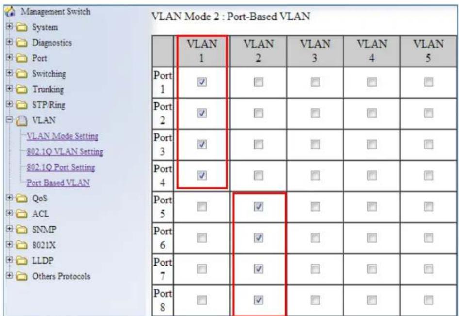
Figure 84: Port Based VLAN – Example 1
In the example below, ports 1 through 6 are all on their own VLAN and cannot communicate with each other. Port 7 and 8 are members of all 6 VLANS and therefore can communicate with all ports that are in any of the VLANs that they share membership with.
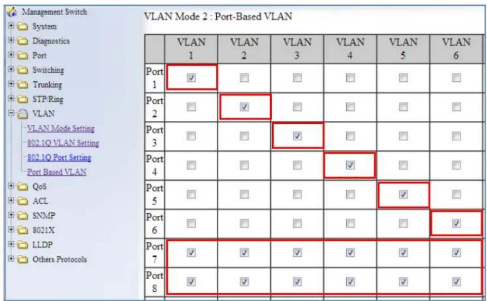
Figure 85: Port Based VLAN – Example 2
To add or remove ports from a specific VLAN:
- Select or deselect the checkbox to the right of the Port and below the VLAN ID for the port you want to add or remove from a VLAN.
- Click on the Submit button.
- Save the configuration (see the Save Configuration Page)
Port Based VLAN Configuration Examples using CLI Commands
To configure port based VLANs use the following CLI commands (for more information on CLI command usage see CLI Command Usage)
CLI Command Mode: Interface Configuration Mode
CLI Command Syntax: switchport portbase add vlan <1 - 16>
Usage Example (to add a port to a single VLAN):
switch_a>enable
switch_a#configure terminal
switch_a(config)#interface fe1
switch_a(config-if)#switchport portbase add vlan 1
switch_a(config-if)#q
switch_a(config)#q
switch_a#
Usage Example (to add a port to multiple VLANs):
switch_a>enable
switch_a#configure terminal
switch_a(config)#interface fel
switch_a(config-if)#switchport portbase add vlan 1
switch_a(config-if)#switchport portbase add vlan 2
switch_a(config-if)#switchport portbase add vlan 3
switch_a(config-if)#switchport portbase add vlan 4
switch_a(config-if)#q
switch_a(config)#q
switch_a#
VLAN Configuration in 802.1Q Tag Based VLAN Mode
General Overview
802.1Q VLAN configuration consists of the following four elements:
- Creating all VLANs in the VLAN database.
- Configuring an incoming untagged packet's VLAN association rule: this is accomplished by configuring the PVID setting on each individual port.
- Configuring the ports that are associated with a VLAN to allow the packets that belong to that VLAN to exit and enter the switch through that port.
- Configuring the tag action on the outgoing packets for each VLAN, that is to say, deciding on whether or not an outgoing packet will be tagged with the VLAN number that the packet belongs to.
All ports can be configured with different Port Types that have different tagging restrictions as defined below.
- Access Port - If a port is configured to be an Access Port, then this port can only be a member of a single VLAN based on the Access Port's PVID VLAN setting, and this port's outgoing packets cannot be modified to contain a VLAN Tag.
- Trunk Port - If a port is configured to be a Trunk Port, then this port can be a member of multiple VLANs. This port's outgoing packets will be automatically modified to contain a VLAN tag of the VLAN that the packet belongs to, with the exception of the PVID VLAN on that port. The PVID VLAN on a Trunk Port will not be automatically modified to contain a VLAN tag of the PVID VLAN.
- Hybrid Port - A Hybrid Port has no restriction on it. If a port is configured to be a Hybrid Port, then this port can be a member of multiple VLANs, and this port's outgoing packets can be configured to be either with or without a VLAN tag of the VLAN that the packet belongs to, including the PVID VLAN of the Hybrid Port.
For all three types of ports above, if an incoming packet contains a VLAN tag, then the packet's VLAN association rule will be based on the VLAN Tag.
Enabling 802.1Q Tagged Based VLAN
To navigate to the VLAN Mode Setting page:
-
Click on the + next to VLAN.
-
Click on VLAN Mode Setting.
To enable 802.1Q Tagged Based VLAN on the switch:
-
Select Tag-based VLAN from the dropdown box (see below)
-
Click on the Submit button.
-
Save the configuration (see the Save Configuration Page)
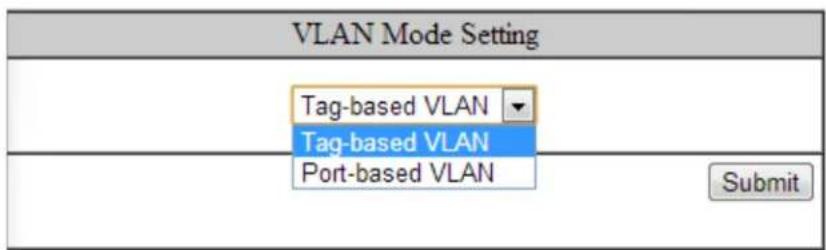
Figure 86: Tag-based VLAN
Configuring 802.1Q VLAN Database
To navigate to the 802.1Q VLAN Setting page:
- Click on the + next to VLAN.
- Click on 802.1Q VLAN Setting.
To configure the 802.1Q VLAN Database, do the following:
- Click on the Add VLAN button (see Figure 87).
| VLAN Setting | Add VLAN | Delete VLAN | ||
| VLAN ID | VLAN NAME | |||
| VLAN1 | default | |||
Figure 87: Add VLAN
- Enter the VLAN ID.
- Enter the VLAN Name.
- Select Attach or Detach for the CPU Port.
a. Attaching the CPU to a VLAN is typically done on the Management VLAN.
- Select the ports to be a member of the VLAN (see Configuring the VLAN Egress (outgoing) Member Ports)
- Click on Submit button.
- Repeat for all the VLANs that are needed.
- Save the configuration (see the Save Configuration Page)
| VLAN ID(2--4094) | VLAN Name | |||
| CPU Port | Attach ▼ | |||
| VLAN Setting | ||||
| PORT | VLAN Member | Tag or Untag | ||
| fe1 | □ | Untag ▼ | ||
| fe2 | □ | Untag ▼ | ||
| fe3 | □ | Untag ▼ | ||
| fe4 | □ | Untag ▼ | ||
| fe5 | □ | Untag ▼ | ||
| fe6 | □ | Untag ▼ | ||
Figure 88: Add VLAN Page
802.1Q Tag Based VLAN Configuration Examples Using CLI Commands
Configuring a 802.1Q VLAN
To configure a 802.1Q VLAN on a switch use the following CLI commands (for more information on CLI command usage see CLI Command Usage)
CLI Command Mode: VLAN Database Configuration Mode
CLI Command Syntax: switchport portbase add vlan <1 - 16> vlan <1 - 4094> bridge 1 name VLAN NAME state enable
Usage Example:
switch_a>enable
switch_a#configure terminal
switch_a(config)#vlan database
switch_a(config-vlan)#vlan 100 bridge 1 name Management state enable
switch_a(config-vlan)#vlan 200 bridge 1 name Accounting state enable
switch_a(config-vlan)#vlan 300 bridge 1 name Sales state enable
switch_a(config-vlan)#q
switch_a(config)#q
switch_a#
Configuring an IP Address for a Management VLAN
To configure the IP address for the management VLAN use the following CLI commands
CLI Command Mode: Interface Configuration Mode
CLI Command Syntax: ip address IP_ADDRESS/PREFIX [e.g. 10.0.0.1/24]
Usage Example:
switch_a>enable
switch_a#configure terminal
switch_a(config)#interface vlan1.100
switch_a(config-if)#ip address 192.168.100.10/24
switch_a(config-if)#q
switch_a(config)#q
switch_a#
Removing an IP Address from a Management VLAN
To remove an IP address from a management VLAN use the following CLI commands
CLI Command Mode: Interface Configuration Mode
CLI Command Syntax: no ip address
Usage Example:
switch_a>enable
switch_a#configure terminal
switch_a(config)#interface vlan1.100
switch_a(config-if)#no ip address
switch_a(config-if)#q
switch_a(config)#q
switch_a#
Configuring an Access Port
To configure an Access Port use the following CLI commands:
CLI Command Mode: Interface Configuration Mode
CLI Command Syntax: switchport mode access
CLI Command Syntax: switchport access vlan <1 - 4094>
Usage Example:
switch_a>enable
switch_a#configure terminal
switch_a(config)#interface fel
switch_a(config-if)#switchport mode access
switch_a(config-if)#switchport access vlan 100
switch_a(config-if)#q
switch_a(config)#q
switch_a#
Configuring a Trunk Port
To configure a Trunk Port use the following CLI commands:
CLI Command Mode: Interface Configuration Mode
CLI Command Syntax: switchport mode trunk
CLI Command Syntax: switchport trunk allowed vlan add 100,200,300
CLI Command Syntax: switchport trunk native vlan 1
Usage Example:
switch_a>enable
switch_a#configure terminal
switch_a(config)#interface fe7
switch_a(config-if)#switchport mode trunk
switch_a(config-if)#switchport trunk allowed vlan add 100,200,300
switch_a(config-if)#switchport trunk native vlan 1
switch_a(config-if)#q
switch_a(config)#q
switch_a#
Add an IP to the Management VLAN
To navigate to the System/IP Address page:
- Click on the + next to System.
- Click on IP Address.
To add an IP for a Management VLAN:
- Enter the IP address and subnet mask for the management VLAN
- Click on the Submit button (see below).
- Save the configuration (see the Save Configuration Page)
| VLAN ID | IP Address | IP Subnet Mask |
| 1 | 10.58.7.78 | 255.255.255.0 |
| 100 | 192.168.100.12 | 255.255.255.0 |
| Default Gateway | Disable ▼ | |
| Apply & Save | ||
Figure 89: Management VLAN IP Address
To delete an IP from a VLAN (the default VLAN, for an example):
- Delete the IP and the subnet mask of the default VLAN and leave it as blank
- Click on the Submit button.

Warning: Before completing the steps above, make sure that you have already set up another management IP on another VLAN, and have set up a port properly for accessing that VLAN.
Configuring the Port Type and the PVID setting
To navigate to the 802.1Q Port Setting page:
- Click on the + next to VLAN.
- Click on 802.1Q Port Setting.
To configure the proper port type and the PVID setting for each switch port:
- Choose the port type for each port in the drop-down list (see General Overview for port type details).
- Enter the PVID VLAN for each port (see below).
- Enter the Priority Level (optional).
- Click on the Update Setting button.
- Save the configuration (see the Save Configuration Page)

Warning: Modifying the Port Type using the Web GUI will cause that switch port to lose all its current VLAN membership and become a member port for the PVID VLAN only. You will lose your current connection to the switch, should you choose to modify the PVID of the port that connects your Computer to the switch.
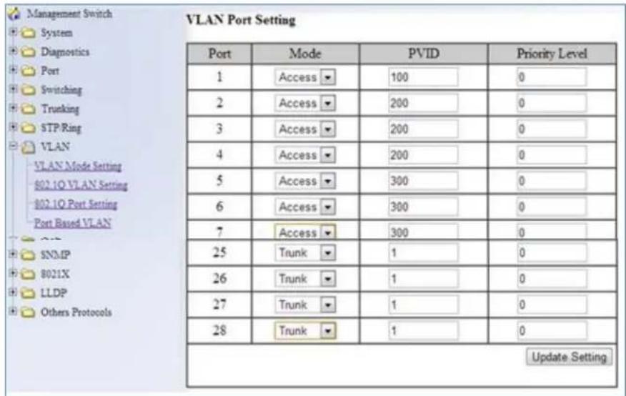
Figure 90: VLAN Port Setting
Configuring the VLAN Egress (outgoing) Member Ports
To navigate to the 802.1Q VLAN Setting page:
- Click on the + next to VLAN.
- Click on 802.1Q VLAN Setting.
To configure the egress member ports for each VLAN:
- Click on the VLAN link that you want to configure (see below).

Figure 91: VLAN Links
- Check the check box next to the port number that should be the egress member port for this VLAN
- Click on the Submit button (see Figure 92).

Note: If an egress member port for a VLAN has the PVID set on that port to be the same as the VLAN, then that port will automatically be configured as an egress member port for the VLAN by the switch. If a check box is not checked and is grayed out, it is because that port is an Access Port with the PVID set to be a different VLAN than the current VLAN.

Figure 92: VLAN Ports
If any of the egress member ports are Hybrid ports, you must also configure the Tag action on this port (see Figure 93).
- Select the correct Tag option in the drop down list under Tag or Untag for this port.
- Click on the Submit button.
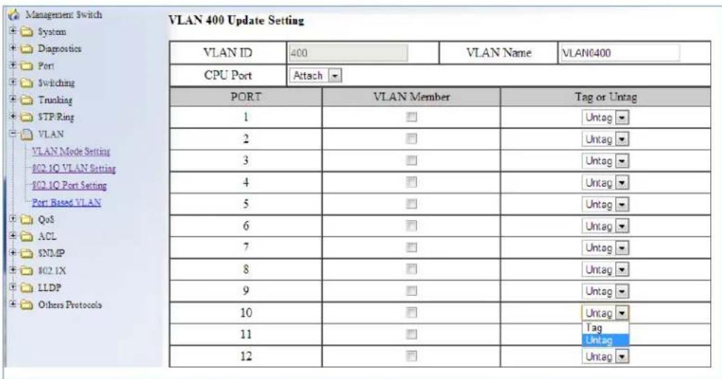
Figure 93: Tag or Untag ports
QOS
QoS (Quality of Service) refers to several related aspects of computer networks that allow the transport of traffic with special requirements. In particular, technology has been developed to allow computer networks to become as useful as telephone networks for audio conversations, as well as supporting new applications with even stricter service demands. Beyond the audio applications that QoS was originally intended, data traffic such as video or real-time information can benefit from QoS.
QoS as it pertains to the switch can be broken down into two types, CoS and DCSP. CoS or Class of Service operates at Layer 2 and was developed by an IEEE working group in the 1990s. CoS uses a 3-bit field called the Priority Code Point (PCP) within an Ethernet frame header when using VLAN tagged frames as defined by IEEE 802.1Q. It specifies a priority value between 0 and 7, inclusive that can be used by QoS disciplines to differentiate traffic. Although this technique is commonly referred to as IEEE 802.1p, there is no standard or amendment by that name published by the IEEE. Rather the technique is incorporated into the IEEE 802.1Q standard which specifies the tag inserted into an Ethernet frame.
Eight different classes of service are available as expressed through the 3-bit PCP field in an IEEE 802.1Q header added to the frame. The way traffic is treated when assigned to any particular class is undefined and left to the implementation. The IEEE however has made some broad recommendations:
| PCP | Priority | Acronym | Traffic Types |
| 1 | 0 (lowest) | BK | Background |
| 1 | 1 | BE | Best Effort |
| 2 | 2 | EE | Excellent Effort |
| 3 | 3 | CA | Critical Applications |
| 4 | 4 | VI | Video, < 100 ms latency and jitter |
| 5 | 5 | VO | Voice, < 10 ms latency and jitter |
| 6 | 6 | IC | Internetwork Control |
| 7 | 7 (highest) | NC | Network Control |
The above recommendations are implemented in the 802.1p Priority submenu.
DSPC or Diffserv Code Point uses the first 6 bits in the ToS field of the IP(v4) packet header. This type of QoS is primarily useful if the QoS needs to pass through a router or routers. We will touch on DSPC briefly later in this section.
Global Configuration Page
Web GUI Interface
To navigate to the QoS Global Configuration page (see below):
- Click on the + next to QoS.
- Click on Global Configuration.
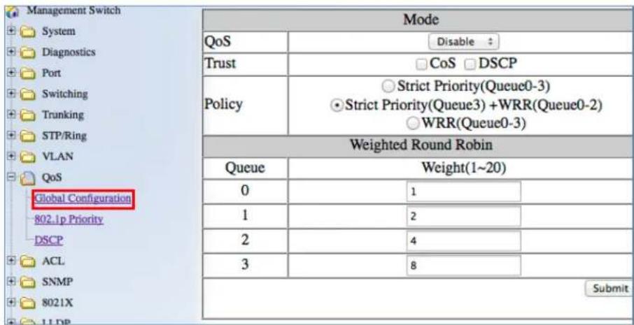
Figure 94: Global Configuration
To Enable the QoS settings:
- Enable QoS, by selecting the drop-down box to the right of the QoS option.
- Choose CoS and/or DSCP next to the Trust option.
- Select the desired option next to Policy:
a. Strict Priority (Queue0-3) – Note: Not all switches support this mode.
Packets must be emptied from the queues in order. Starting with queue 3 and ending with queue 0, the packets in each queue must be completely emptied before the next queue's packets are considered for transmission.
b. Strict Priority(Queue3) +WRR(Queue0-2) – Packets must be emptied from queue 3 first and the three remaining queues are emptied according the WRR weights in the Weighted Round Robin section (see below).
c. WRR (Queue 0 - 3) – each queue is allowed to discharge a certain number of packets (according to the WRR weights in the Weighted Round Robin section) before moving to the next queue.
- Enter the Weight for each queue in the Weight Round Robin section
- Click on the Submit button.
- Save the configuration (see the Save Configuration Page)

Note: Weighted Round Robin – There are four text fields, one for each queue (0 – 3). A number from 1 to 20 can be assigned for each queue. This number is used with WRR policy and is the value of the number of packets that must be emptied from the queue before the next queue is considered. By default, these values are:
| Queue | Weight |
| 0 | 1 |
| 1 | 2 |
| 2 | 4 |
| 3 | 8 |
QoS Global Configuration using the CLI Interface
This section gives information on Command line commands related to QoS and assumes the user has a working knowledge of connecting to the switch using Telnet, SSH or the Serial port. Telnet is enabled by default. To enable or disable Telnet or SSH see the Management Interface section.
For more information on CLI command usage see CLI Command Usage.
Enabling/Disabling QoS
To get to the CLI level to configure QoS:
CLI Command Mode: Interface Configuration Mode
CLI Command Syntax:
mls qos enable
no mls qos
Usage Example – Enabling QoS:
switch_a>enable
switch_a#configure terminal
switch_a(config)#int fel
switch_a(config-if)#mls qos enable
switch_a(config-if)#q
switch_a(config)#q
switch_a#
Usage Example – Disabling QoS:
switch_a>enable
switch_a#configure terminal
switch_a(config)#int fel
switch_a(config-if)#no mls qos
switch_a(config-if)#q
switch_a(config)#q
switch_a#
Enable/Disable QoS Trust
CLI Command Mode: Global Configuration Mode
CLI Command Syntax:
mls qos trust <cos/dscp>
no qos trust
Usage Example – Enable QoS Trust:
switch_a>enable
switch_a#configure terminal
switch_a(config)#mls qos trust cos
switch_a(config)#q
switch_a#
Usage Example – Disable QoS Trust:
switch_a>enable
switch_a#configure terminal
switch_a(config)# no mls qos trust
switch_a(config)#q
switch_a#
Configuring the Egress Expedite Queue
CLI Command Mode: Global Configuration Mode
CLI Command Syntax:
priority-queue strict
priority-queue out
no priority-queue out
mls qos <WRR_WTS> (4 values separated by spaces. Range is 1-20 (See the Usage Example).
Usage Example – Enable QoS Strict Priority (Queue 0-3):
switch_a>enable
switch_a#configure terminal
switch_a(config)#priority-queue strict
switch_a(config)#q
switch_a#
Usage Example – Enable QoS Strict Priority (Queue 3) + WWR (Queue 0-2):
switch_a>enable
switch_a#configure terminal
switch_a(config)#priority-queue out
switch_a(config)#q
switch_a#
Usage Example – Disable QoS Strict Priority:
switch_a>enable
switch_a#configure terminal
switch_a(config)# no priority-queue out
switch_a(config)#q
switch_a#
Usage Example – The following example specifies the bandwidth ratios of the four transmit queues, starting with queue 0, on the switch. WRR_WTS Weighted Round Robin (WRR) weights for the 4 queues (4 values separated by spaces). Range is 1-20.
switch_a>enable
switch_a#configure terminal
switch_a(config)#mls qos 1 2 4 8
switch_a(config)#q
switch_a#
802.1p Priority Page
Web GUI Interface
To navigate to the QoS 802.1p Priority page (see Figure 95):
- Click on the + next to QoS.
- Click on 802.1p Priority.
The 802.1p Priority page allows a user to assign the queues to VLAN priorities (see Global Configuration Page for more information on queues).
Each VLAN priority is expressed as the three-bit PCP field in the 802.1Q header discussed previously. The values shown above are the default values with the higher VLAN priorities corresponding to the higher priority queues.
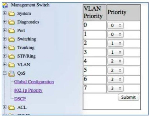
Figure 95: 802.1p Priority
By default, the higher priority queue 3 are assigned to VLAN priorities 6 and 7, queue 2 assigned to VLAN priorities 4 and 5; queue 1 assigned to VLAN priorities 2 and 3; and finally, queue 0 assigned to VLAN priorities 0 and 1.
After making any changes on the page, click on the Submit button to ensure that the changes are stored.
802.1p Priority Submenu – CLI Interface
For more information on CLI command usage see CLI Command Usage.
CLI Command Mode: Global Configuration Mode
CLI Command Syntax:
wrr-queue cos-map
Queue ID. Range is 0-3.
COS_VALUE CoS values. Up to 8 values (separated by spaces).
Usage Example The following example shows mapping CoS values 0 and 1 to queue 1 on the switch:
switch_a>enable
switch_a#configure terminal
switch_a(config)#wrr-queue cos-map 1 0 1
switch_a(config)#q
switch_a#
DSCP Page – HTTP Interface
The DSCP submenu is much like the 802.1p submenu except there are many more DSCP priorities to choose from and they are all assigned to the lowest-priority queue, 0. For each DSCP priority, the user can change the value of the queue to between 0 and 3. See Figure 3 for more information:

Figure 96: DSCP
After changing any values on this page, click on the Submit button to allow them to take effect.
DSCP Submenu – CLI Interface
For more information on CLI command usage see CLI Command Usage.
CLI Command Mode: Global Configuration Mode
CLI Command Syntax:
mls qos map dscp-queue
dscp_value: Up to 8 values (separated by spaces). Range is 0-63.
queue_ID: Range is 0-3.
Usage Example The following example shows mapping DSCP values 0 to 3 to queue 1 on the switch:
switch_a>enable
switch_a#configure terminal
switch_a(config)#mls qos map dscp-queue 0 1 2 3 to 1
switch_a(config)#q
switch_a#
QoS Interface Commands – CLI Interface
For more information on CLI command usage see CLI Command Usage.
To assign a VLAN Priority to an Interface:
CLI Command Mode: Interface Configuration Mode
CLI Command Syntax: user-priority <0-7>
Usage Example The following example shows mapping DSCP values 0 to 3 to queue 1 on the switch:
switch_a>enable
switch_a#configure terminal
switch_a(config)#interface fel
switch_a(config-if) user-priority 4
switch_a(config-if)#q
switch_a(config)#
ACL (ACCESS CONTROL LIST)
This section applies only to specific models of EtherWAN Switches.
The settings in the ACL feature of the EtherWAN switch can be used to control which packets are allowed to enter the switch (Packet Filtering), as well as to control the amount of bandwidth that can be allocated for those packets (Bandwidth Policing).
General Overview
The ACL feature filters packets through access control lists. Any combination of 4 different types of access control lists (called Access Lists) can be used for this purpose. These four different types of access control lists are explained below:
IP Access List:
This Access List can be used to filter IP packets based on the packet's source IP address only.
IP Access List (Extended):
This Access List can be used to filter IP packets based on the packet's source and destination IP addresses, as well as the packet's source and destination transport layer protocol port numbers.
MAC Access List:
This Access List can be used to filter Ethernet packets based on the packet's source and destination Ethernet addresses as well as the packet's Ethernet payload protocol number (EtherType).
Layer 4:
This Access List, if it is used by itself, can only be used to classify IP packets based only on the IP packet's source and destination transport layer protocol port numbers. Use this Access List in conjunction with another type of Access List mentioned above, if you wish to filter any packet from entry to the switch that did not match the classification rules from this Access Lists, otherwise all packets that did not match the classification rules of this Access List will also be allowed entry into the switch.

Note: You can use any combination of the above four types of Access Lists to packets through the ACL feature, the switch will apply these Access Lists in the case that they were configured. Since Access List filters allow packets through, there is not be at least one catch all deny rule that can deny all types of packets from entry
to the switch in the very last Access List, This will ensure that only packets specified in the access list will be allowed.
Configuring ACL
To navigate to the ACL/ACL Configuration page:
- Click on the + next to ACL.
- Click on ACL Configuration.
In order to enable the ACL feature on the EtherWAN switch, the QoS feature must be enabled on the switch as well. In order to apply the ACL packet filtering features on a port, you must:
- Create and configure an ACL Access List first.
- Next, you will need to create and configure an ACL Class Map,
- Associate the previously created ACL Access Lists to this ACL Class Map.
- Next, create and configure an ACL Policy Map
- Associate all the appropriate and necessary ACL Classes into this ACL Policy Map.
- Then apply this ACL Policy Map (and all the Access Lists that it contains) to a specific port.
To enable the ACL feature on the EtherWAN switch first enable the QoS feature using the steps below (see Figure 97).
- From the drop-down list next to QoS, choose the Enable option
- Click on the Submit button. For more details see QoS.

Figure 97: Enabling QoS
ACL Policy Map
To create a new ACL Policy Map, follow the instructions below.
- Make sure that the Create option is selected from the drop-down list next to Policy Map (see below)
- Next, make sure that the Create option is selected from the drop-down list under Class Name (see below).
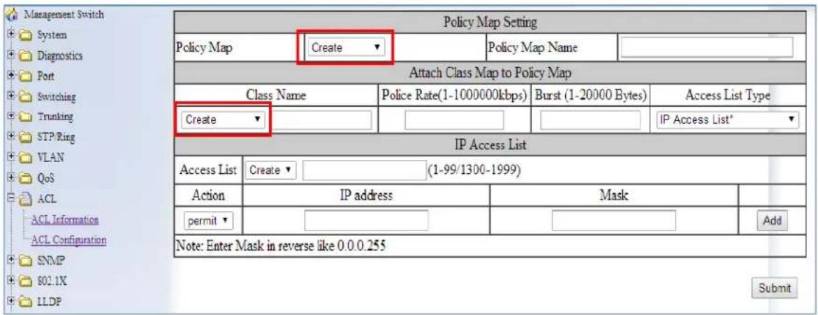
Figure 98: Policy Map
Next, you will be creating a new ACL Access List which is necessary to create an ACL Class Map. From the information listed below you will find the configuration steps necessary for all of the four available ACL Access Lists. You can choose one Access List from the below list and follow the steps there to complete the configuration for that Access List. One Access List can be created during the initial ACL Policy Map creation process. After you have chosen just one Access List from below and have finished all the configuration steps for it, please continue on to step #3.
IP Access List
![Policy Map Setting Policy Map Create Policy Map Name Attach Class Map to Policy Map Class Name Police Rate(1-1000000kbps) Burst (1-20000 Bytes) Access List Type Create IP Access List* 2. & 3. 4. IP Access List * Access List Create (1-99/1300-1999) Action IP address Mask permit 5. & 9 192.168.1.224 6. 0.0.0.31 Remove permit ← [ ] 7. Add Note: Enter Mask in reverse like 0.0.0.255 8. Submit](/content/2026/05/986160/images/aedfe0c9d11a344d96a3749f5f5e2d8a385bac90907fd9668168fa699fd86638.jpg)
Figure 99: IP Access List
To configure an IP Access List (See Figure 99 above):
- Select the IP Access List option from the drop-down list below Access List Type.
- If you have already created an IP Access List previously and would like to apply it to the new ACL Class, then select the Access List number from the drop-down list next to Access List.
- If you want to create a new IP Access List, make sure that the Create option is selected from the drop-down list next to Access List.
- To give the new IP access list an ID, enter a number in the range from 1 – 99, or from 1300 – 1999, into the entry field next to the "Create" option drop-down list.
- You can enter a source IP address to allow an IP packet with that source IP to gain entry into the switch. To do this, choose the permit option from the drop-down list under the Action column.
- Next, enter the source IP address into the entry field from the IP address column.
- Next, enter the Comparison Mask for the source IP address in reverse logic, into the entry field from the Mask column. In reverse logic, 255.255.255.0 would be 0.0.0.255.
-
Next, click on the Add button.
-
You can enter a source IP address in order to deny an IP packet with that source IP to gain entry into the switch. To do so, you must choose the deny option from the drop-down list under the Action column. Next, enter the IP address and mask as described in step 6 and 7.
a. You can also use the any wild card in lieu of entering a source IP address in the entry field from the IP address column. You will need to do this if you wish to deny any additional IP packet from entry to the switch that did not match any of the previous rules from all the previous access control lists, otherwise these additional IP packets will also be allowed entry into the switch.
IP Access List (Extended)

Figure 100: Access List Extended
- Select the IP Access List (Extended) option from the drop-down list below Access List Type (see Figure 100)
- To apply an existing Extended IP Access to the new ACL Class, then select the Access List number for the previously configured Extended IP Access List from the drop-down list next to Access List.
-
if you want to create a new Extended IP Access List, verify that the Create option is selected from the drop-down list next to Access List.
-
To give this particular Extended IP access list an ID, enter a number in the range from 100 – 199, or from 2000 – 2699, into the entry field next to the Create option drop-down list.
- You can enter a source and a destination IP address to allow an IP packet with these pair of IP addresses to gain entry into the switch. To do this, choose the permit option from the drop-down list under the Action column.
- Next, enter the source IP address of the IP packet into the entry field under the Source Address column.
- Next, enter the comparison Mask for the source IP address in reverse logic (a binary "0" in the mask means "this bit position needs to checked", whereas a binary "1" in the mask means "this bit position does not need to be checked") into the entry field from the Source Wildcard Bits column. In reverse logic, 255.255.255.0 is listed as 0.0.0.255.
- Next, enter the destination IP address of the IP packet into the entry field under the Destination Address column.
- Next, enter the comparison Mask for the destination IP address in reverse logic into the entry field from the Destination Wildcard Bits column.
- Next, click on the Add button.
- You can also filter the IP packet using the packet's source and destination Transport Layer protocol port numbers in addition to the source and destination IP addresses. Just enter the source Transport Layer protocol port number into the entry field under the port (1-65535) column following the source IP address comparison mask column. Next, enter the destination Transport Layer protocol port number into the entry field under the port (1-65535) column following the destination IP address comparison mask column.
- To enter an extended IP access list entry in order to deny the entry of an IP packet into the switch, you must choose the deny option from the drop-down list under the Action column. Next, enter the IP addresses and Transport Layer protocol port numbers using the same steps as in the previous two bullets.
- You can also use the any wild card in lieu of entering an IP address in the entry field from both the Source Address and Destination Address column. You will need to do this if you wish to deny any additional IP packet from entry to the switch that did not match any of the previous rules from all the previous access control lists, otherwise these additional IP packets will also be allowed entry into the switch.
Mac Access List

Figure 101: MAC Access list
- To configure a MAC access list, select the MAC Access List option from the dropdown list below Access List Type (see Figure 101).
- If a MAC Access List was previously created and you would like to apply it to the new ACL Class, then select the Access List number for the previously configured MAC Access List from the drop-down list next to Access List. If you want to create a new MAC Access List, insure that the Create option is selected from the drop-down list next to Access List.
-
To give this particular MAC Access List an ID, enter a number in the range from 2000 – 2699, into the entry field next to the Create option drop-down list.
-
You can enter a source and a destination Ethernet address to allow a specific Ethernet packet entry into the switch. To do so, you must choose the permit option from the drop-down list under the Action column.
- Next, enter the source Ethernet address of the Ethernet packet into the entry field under the Source MAC column.
- Next, enter the Comparison Mask for the source Ethernet address in reverse logic (Ex. 255.255.255.0 is 0.0.0.255 in reverse logic) into the entry field from the Mask column following the Source MAC column.
- Next, enter the destination Ethernet address of the Ethernet packet into the entry field under the Destination MAC column.
- Next, enter the comparison Mask for the destination Ethernet address in reverse logic into the entry field from the Mask column following the Destination MAC column. Next, choose the appropriate encapsulation format of the Ethernet packet that you want to allow entry into the switch from the drop-down list under the Format column.
- Next, click on the Add button.
- You can also filter the Ethernet packet using the Ethernet packet payload's EtherType number in addition to the source and destination Ethernet addresses. Just enter the EtherType number of the Ethernet packet into the entry field under the Ether type column.
- Next, you can also enter a comparison mask for the EtherType number into the entry field under the Mask column next to the Ether type column.
- To enter a MAC Access List entry in order to deny the entry of an Ethernet packet into the switch, you must choose the deny option from the drop-down list under the Action column.
- Next, enter the Ethernet addresses and the EtherType number using the same steps as in steps 11 and 12.
- You can also use the any wild card in lieu of entering an Ethernet address in the entry field from both the Source MAC and Destination MAC column. You will need to do this if at any time this Access List should become the very last Access List rule in a ACL Policy Map to serve as the catch all deny rule in order to deny any and all types of packets from entry into the switch that did not match any of the previous rules from all the previous access control lists.
Layer 4

Figure 102: Layer 4
- To use the Layer 4 access list feature and apply it to the new ACL Class, select the Layer 4 option from the drop-down list below Access List Type (see Figure 102).
- You can enter a source or destination Transport Layer protocol port number to allow any IP packet with this port number to gain entry into the switch. To do this, choose the appropriate port number type (Source port or Destination port) from the dropdown list next to Option.
- Next, enter the correct port number into the entry field next to "TCP/UDP Port No.(1-65535)".
- After you have finished configuring just one ACL Access List from the previous step, you must now create a name for the new ACL Class Map that will be associated with this Access List. To do this, just enter a name for the new ACL Class Map into the text box under Class Name (see Figure 103).

Note: Since this particular Access List type does not contain any deny rules, this less List will have to be used in conjunction with another type of Access List, if you to filter any packet from entry to the switch that did not match the classification rules of this Access Lists. Otherwise all packets that did not match the classification rules of Access List will also be allowed entry into the switch.

Figure 103: IP Access List Name
Bandwidth Limiting
- The amount of bandwidth that is being allocated for the traffic that is being allowed under this new ACL Class can also be limited. To do this, enter the bandwidth amount that you want to allocate for the traffic in the entry field under Police Rate (1-1000000Kbps) (see Figure 104).
- To allow certain amount of bursting in the traffic enter the maximum number of bytes that are allowed in a single continuous burst, under Burst (1-20000 Bytes).

Figure 104: Police Rate
- Next, enter a name in the entry field next to "Policy Map Name" for the new ACL "Policy Map" that you are currently creating, and click on the submit button (see Figure 105).

Figure 105: Policy Map Name
Applying a Policy Map to a Port
To apply an ACL Policy Map to a port, just follow the instructions below.
- Select the correct ACL Policy Map from the drop-down list next to Policy Map (see Figure 106).
- Next, check the boxes below Attach Class Map to Policy Map next to all the ports that you would like to apply this Policy Map to.
- Click on the Attach button.

Figure 106: Applying a Policy Map to a Port
Modifying/Adding an Existing Policy Map
To modify or add to an existing ACL Policy Map, just follow the instructions below.
-
Select the correct ACL Policy Map from the drop-down list next to Policy Map (see Figure 107)
-
Next, detach the Policy Map from all the ports by deselecting the check boxes below Attach Class Map to Policy Map for the ports you would like to remove the policy map.
- Click on the Attach button.
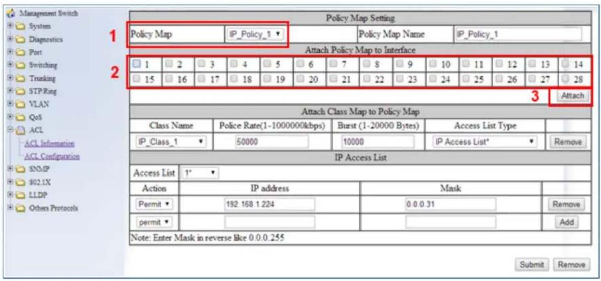
Figure 107: Modifying a Policy Map
Adding a New ACL Class to an Existing Policy Map
If you would like to create a new ACL Class and add it to this ACL Policy Map follow the steps below
- Make sure that the Create option is selected from the drop-down list under Class Name (see Figure 108)
- Next, follow the instructions on how to create a new ACL Policy Map on page 209.
- Next, click on the Submit button.

Figure 108: Adding a New ACL Class to an Existing Policy Map
Adding an Existing ACL Class to an Existing Policy Map
If you would like to add an existing ACL Class to this ACL Policy Map (see Figure 109):
- Select the correct ACL Class from the drop-down list under Class Name, and then wait for the GUI to update itself.
- Click on the Submit button.

Figure 109: Policy Map Setting – Class Name
- You can confirm that the ACL Class has been added correctly to this Policy Map by checking the dropdown list under "Class Name". If you see the newly added ACL Class in the list above the dash line, then it has been added properly (see below).

Figure 110: Policy Map Setting
Removing an ACL Class
If you would like to remove an ACL Class from this ACL Policy Map:
- Make sure to select the correct ACL Class that is above the dash line from the dropdown list under Class Name (see Figure 111).
- Next, click on the Remove button under Attach Class Map to Policy Map.

Figure 111: Removing an ACL Class
- You can confirm that the ACL Class has been removed from this Policy Map by checking the dropdown list under Class Name. If you do not see the ACL Class in the list above the dash line, but see it below the dash line, then it means it has been removed from this Policy Map (see Figure 112).
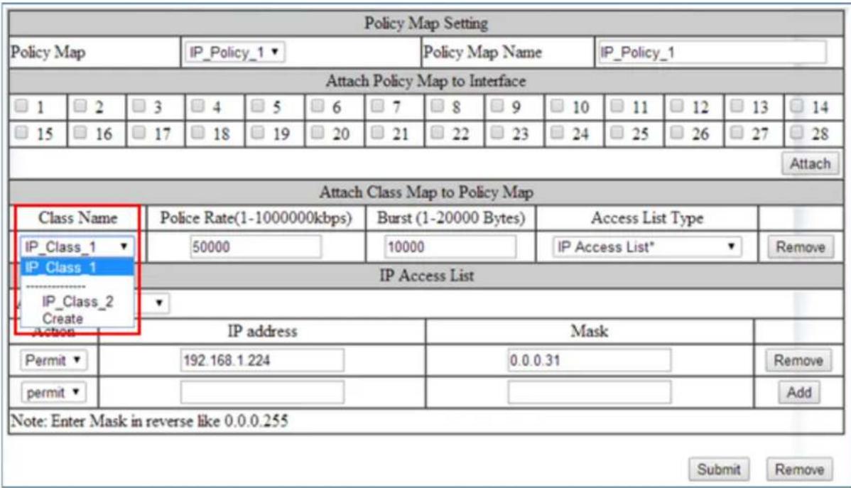
Figure 112: Verifying ACL Class Removal
To remove an existing ACL Policy Map entirely, follow the instructions below:
- Select the correct ACL Policy Map that you want to remove entirely, from the dropdown list next to Policy Map (see Figure 113)
- Next, detach the Policy Map from all the ports by deselecting all the check boxes below Attach Class Map to Policy Map for all the selected ports,
- Click on the Attach button.
- Next, click on the Remove button.

Figure 113: Removing a Policy Map
To remove an existing ACL Class entirely, follow the instructions below.
- Make sure that the ACL Class is not associated with any ACL Policy Map. If it is, you must remove it from that Policy Map first (see Modifying/Adding an Existing Policy Map).
- Next, make sure that the Create option is selected from the drop-down list next to Policy Map (see Figure 114).
- Next, select the correct ACL Class from the drop-down list under Class Name, and then wait for the GUI to update itself.
- Next, click on the Remove button under Attach Class Map to Policy Map
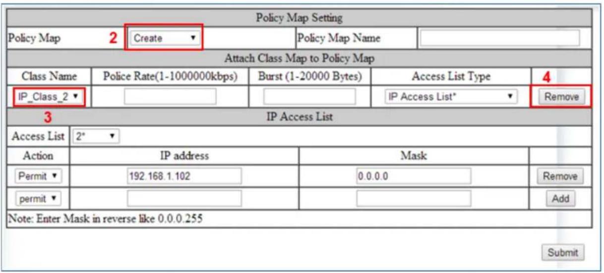
Figure 114: Policy Map 2
- You can confirm that this ACL Class has been removed completely by checking the drop-down list under "Class Name". If you do not see the ACL Class in the list then it means it has been completely removed (see below).
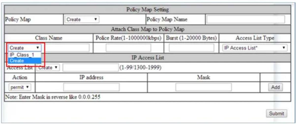
Figure 115: Policy Map 3
ACL Configuration Examples Using CLI Commands
For more information on CLI command usage see CLI Command Usage.
Enabling QoS
To enable the ACL feature on the EtherWAN switch by enabling the QoS feature on the switch, just follow the steps below:
CLI Command Mode: Global Configuration Mode
CLI Command Syntax: mls qos enable
Usage Example:
switch_a>enable
switch_a#configure terminal
switch_a(config)# mls qos enable
switch_a(config)#q
switch_a#
Creating a Standard IP Access List
To create a new Standard IP Access List to allow or deny an IP address/range access to the switch, use the following CLI commands with the Access list ID in the range from 1 – 99, or from 1300 – 1999:
CLI Command Mode: Global Configuration Mode
CLI Command Syntax:
ip-access-list <1-99, 1300-1999> permit <source IP> <source bit mask>
ip-access-list <1-99, 1300-1999> deny <source IP> <source bit mask>
ip-access-list <1-99, 1300-1999> deny any
Usage Example:
switch_a>enable
switch_a#configure terminal
switch_a(config)# ip-access-list 1 permit 192.168.1.224 0.0.0.31
switch_a(config)# ip-access-list 1 deny 192.168.1.224 0.0.0.31
switch_a(config)# ip-access-list 1 deny any
switch_a(config)#q
switch_a#
Creating an Extended IP Access List
To create a new Extended IP Access List to allow or deny an source IP address/range and destination IP address/range pair access to the switch, use the following CLI commands with the Access list ID in the range from 100 – 199, or from 2000 – 2699:
CLI Command Mode: Global Configuration Mode
CLI Command Syntax:
ip-access-list <100-199, 2000-2699> permit ip
ip-access-list <100-199, 2000-2699> deny ip
ip-access-list <100-199, 2000-2699> deny ip any any
Usage Example:
switch a>enable
switch_a#configure terminal
switch_a(config)#ip-access-list 100 permit ip 192.168.1.224 0.0.0.31
192.168.1.224 0.0.0.31
switch a(config)#ip-access-list 100 deny ip 192.168.1.224 0.0.0.31
192.168.1.224 0.0.0.31
switch a(config)#ip-access-list 100 deny ip any any
switch a(config)#q
switch a#
Creating a MAC Access List
To create a new MAC Access List to allow or deny a source and destination Ethernet address pair access to the switch, use the CLI commands below with the Access list ID in the range from 100 – 199, or from 2000 – 2699.:
CLI Command Mode: Global Configuration Mode
CLI Command Syntax:
mac-access-list <2000-2699> permit
1=Ethernet II, 2=SNAP, 4=802.3, 8=LLC> ether-type
mac-access-list <2000-2699> deny
<destination MAC address> <destination bit mask> <encapsulation format: 1=Ethernet II, 2=SNAP, 4=802.3, 8=LLC> ether-type <EtherType> < EtherType bit mask>
mac-access-list <2000-2699> deny any any <encapsulation format: 1=Ethernet II, 2=SNAP, 4=802.3, 8=LLC> ether-type <EtherType> < EtherType bit mask>
Usage Example:
switch_a>enable
switch_a#configure terminal
switch_a(config)#mac-access-list 2000 permit 00e0.b321.03de
0000.0000.0000 00e0.b321.03df 0000.0000.0000 1 ether-type 800 0000
switch_a(config)#mac-access-list 2000 deny 00e0.b321.03de
0000.0000.0000 00e0.b321.03df 0000.0000.0000 1 ether-type 800 0000
switch_a(config)#mac-access-list 2000 deny any any 1 ether-type 800 0000
switch_a(config)#q
switch_a#
Creating an ACL Class Map with Layer 4 Access List
In order to create a Layer 4 Access List you must create it within an ACL Class Map. Use the CLI commands below to create an ACL Class Map together with the Layer 4 Access List. The Layer 4 Access List only classifies the ingress packets for the ACL Policy Map that it is associated with; therefore, all packets will be allowed entry to the switch with the Layer 4 Access List. You will have to use this Access List in conjunction with another type of Access List, if you wish to filter any packet that did not match the classification rules from this Access List.

Note: The bandwidth policing capabilities of the ACL Class cannot be configured here; n only be configured during the ACL Policy Map creation or modification:
CLI Command Mode:
Global Configuration Mode
Class Map Configuration Mode
CLI Command Syntax:
class-map <Class Map Name>
match layer4 source-port
Usage Example:
switch_a>enable
switch_a#configure terminal
switch_a(config)#class-map FTP
switch_a(config-cmap)#match layer4 destination-port 21
switch_a(config-cmap)#q
switch_a(config)#
switch_a(config)#class-map FTP_Download
switch_a(config-cmap)#match layer4 source-port 20
switch_a(config-cmap)#q
switch_a(config)#q
switch_a#
Creating a ACL Class Map with an IP or MAC Access List
To create a new ACL Class Map with a Standard/Extended IP Access List or a MAC Access List, you must have first created a Standard/Extended IP Access List or MAC Access List already. You can then use the CLI commands below to create a new ACL Class Map and assign one (you can only assign one Access List per Class Map) existing Standard/Extended IP Access List, or MAC Access List, to the ACL Class Map by referencing its Access list ID.

Note: The bandwidth policing capabilities of the ACL Class cannot be configured here; it only be configured during the ACL Policy Map creation or modification:
CLI Command Mode:
Global Configuration Mode
Class Map Configuration Mode
CLI Command Syntax:
class-map
match access-group
Usage Example:
switch_a>enable
switch_a#configure terminal
switch_a(config)#class-map Layer_2-3_Class
switch_a(config-cmap)#match access-group 1
switch_a(config-cmap)#q
switch_a(config)#q
switch_a#
Creating an ACL Policy Map
To create a new ACL Policy Map you must have first created the ACL Class Maps that you want to assign to the ACL Policy Map. You can then use the CLI commands below to create the new ACL Policy Map and assign one or multiple existing ACL Class Maps to the ACL Policy Map by referencing its ACL Class Map name. You can also complete or modify the bandwidth policing capabilities of the ACL Class Maps used during the ACL Policy Map creation process
CLI Command Mode:
Global Configuration Mode
Policy Map Configuration Mode
Policy Map Class Configuration Mode
CLI Command Syntax:
policy-map
class
police <1-1000000> <1-20000> exceed-action drop
Usage Example:
switch_a>enable
switch_a#configure terminal
switch_a(config)#policy-map IP_Policy_1
switch_a(config-pmap)#class IP_Class_1
switch_a(config-pmap-c)#police 50000 5000 exceed-action drop
switch_a(config-pmap-c)#q
switch_a(config-pmap)#class IP_Class_2
switch_a(config-pmap-c)#police 50000 5000 exceed-action drop
switch_a(config-pmap-c)#q
switch_a(config-pmap)#class IP_Class_3
switch_a(config-pmap-c)#police 50000 5000 exceed-action drop
switch_a(config-pmap-c)#q
switch_a(config-pmap)#q
switch_a(config)#q
switch_a#
Appling an Existing ACL Policy to a Port
To apply the ACL packet filtering features on a port, you must have first created an ACL Policy already. You can then use the CLI commands below to apply the existing ACL Policy to a port.
CLI Command Mode:
Global Configuration Mode
Interface Configuration Mode
CLI Command Syntax:
interface
service-policy input
Usage Example:
switch_a>enable
switch a#configure terminal
switch_a(config)#interface fel
switch_a(config-if)#service-policy input IP_Policy_1
switch_a(config-if)#q
switch_a(config)#q
switch_a#
Deleting an ACL Class
You can use the CLI commands below to delete an existing ACL Class.
CLI Command Mode: Global Configuration Mode
CLI Command Syntax: no class-map
Usage Example:
switch_a>enable
switch_a#configure terminal
switch_a(config)#no class-map IP_Class_1
switch_a(config)#q
switch_a#
Deleting an ACL Policy
You can use the below CLI commands to delete an existing ACL Policy:
CLI Command Mode: Global Configuration Mode
CLI Command Syntax: no policy-map
Usage Example:
switch_a>enable
switch_a#configure terminal
switch_a(config)#no policy-map IP_Policy_1
switch_a(config)#q
switch_a#
SNMP
SNMP is a TCP/IP application layer network management protocol that allows any TCP/IP device to be managed across a TCP/IP network. It is based on the client-server paradigm. The server (called a SNMP Agent) runs a process on the managed device that listens for a client's (a network management software running on a computer, usually called a NMS, short for Network Management Station) polling requests to fetch or to set a data item on the managed device. The SNMP Agent can also send alert messages (called Traps) to a NMS automatically, based on the occurrence of certain events on the device that the Agent resides. Note that SNMP is enabled by default.
SNMP General Settings
To navigate to the SNMP General Settings page:
- Click on the + next to SNMP.
- Click on SNMP General Settings.
To configure the general settings for the SNMP feature (see Figure 116):
- The SNMP server on the switch can be enabled or disabled by selecting the appropriate choice from the dropdown list next to SNMP Status.
- The description field displays the switch model and port configuration by default. If needed, enter a short description (up to 256 characters) into this field.
- Enter a name into the entry field next to Location, for the purpose of identifying the location of the switch.
- Enter a name (up to 256 characters) into the entry field next to Contact, to identify the entity that is responsible for this switch.
- Enter a trap community name (up to 256 characters) into the entry field next to any one of the 5 Trap community name entry boxes from Trap Community Name 1 to Trap Community Name 5.
a. Community names identify the SNMP Trap community group that the traps on this switch should be sending to. The identical Trap community names should also be set on the NMS hosts that will be receiving the traps. Each name defined corresponds with the Trap host IP address entry box with the same number. For example, Trap Community Name 1 corresponds with Trap Host 1 IP Address.
- Enter an IP address, for the NMS host(s) that should be receiving traps from this switch, into the entry field next to any one of the 5 Trap host IP address entry boxes from Trap Host 1 IP Address to Trap Host 5 IP Address
- Enable or disable the link down trap by selecting the appropriate choice from the drop-down list next to Link Down Trap. This will allow or stop the switch from sending a trap to the identified trap community groups when any port on the switch moves from the link up state to the link down state.
- Enable or disable the link up trap by selecting the appropriate choice from the dropdown list next Link Up Trap. This will allow or stop the switch from sending a trap to the identified trap community groups when any port on the switch moves from the link down state to the link up state.
- Enable or disable the power down trap by selecting the appropriate choice from the drop-down list next Power Down Trap. This will allow or stop the switch from sending a trap to the identified trap community groups when one of the redundant power sources goes down (This feature is not on EX75000 and EX74000, and models with a single power input).
- Enable or disable the power up trap by selecting the appropriate choice from the drop-down list next Power Up Trap. This will allow or stop the switch from sending a trap to the identified trap community groups when one of the redundant power sources powers up (This feature is not on EX75000 and EX74000, and models with a single power input).
- Enable or disable the MAC notification trap by selecting the appropriate choice from the drop-down list next to MAC Notification Trap. This will allow or stop the switch from sending a trap to the identified trap community groups anytime there is a change in the MAC table on certain selected ports of the switch.
- Set the interval between the MAC notification traps that you want the switch to send by entering the interval (in number of seconds from 1 to 65535) into the entry field next to MAC Notification Interval (1 to 65535 seconds).
- Set the size of the MAC notification history table by entering the total number of records (from 1 to 500) that the switch will keep for user to review at any one time into the entry field next to MAC Notification History Size (1 to 500).
- Select which ports on the switch for which traps should be sent when there is a new MAC address added to the MAC table for the port, by checking the appropriate check boxes for these ports in the MAC Notification Added section.
-
Select which ports on the switch for which traps should be sent when there is a MAC address being removed from the MAC table for the port, by checking the appropriate check boxes for these ports in the MAC Notification Removed section.
-
Click on the Update button after you have finished the configuration of the SNMP Server (Agent) General Settings.
- Save the configuration (see the Save Configuration Page)
| SNMP Status 1 | Enable ▼ | ||
| SNMP General Setting | |||
| Description 2 | Etherwan 24TX+2GT Managed Switch | ||
| Location 3 | First_Floor_Closet | ||
| Contact 4 | Administrator | ||
| Trap Community Name 1 | Trap_Group_1 | ||
| Trap Community Name 2 | Trap_Group_2 | ||
| Trap Community Name 3 5 | Trap_Group_3 | ||
| Trap Community Name 4 | Trap_Group_4 | ||
| Trap Community Name 5 | Trap_Group_5 | ||
| Trap Host 1 IP Address | 192.168.1.100 | ||
| Trap Host 2 IP Address | 192.168.1.100 | ||
| Trap Host 3 IP Address 6 | 192.168.1.100 | ||
| Trap Host 4 IP Address | 192.168.1.100 | ||
| Trap Host 5 IP Address | 192.168.1.100 | ||
| Link Down Trap 7 | Enable ▼ | ||
| Link Up Trap 8 | Enable ▼ | ||
| Power Down Trap 9 | Enable ▼ | ||
| Power Up Trap 10 | Enable ▼ | ||
| MAC Notification Trap 11 | Enable ▼ | ||
| MAC Notification Interval (1 to 65535 seconds) 12 | 60 | ||
| MAC Notification History Size (1 to 500) 13 | 100 | ||
| MAC Notification Added 14 | fe1 fe2 fe3 fe4 fe5 fe6 fe7 fe8 ✓ ✓ ✓ ✓ ☐ ☐ ☐ ☐ fe9 fe10 fe11 fe12 fe13 fe14 fe15 fe16 ☐ ☐ ☐ ☐ ☐ ☐ ☐ ☐ fe17 fe18 fe19 fe20 fe21 fe22 fe23 fe24 ☐ ☐ ☐ ☐ ☐ ☐ ☐ gel ge2 ✓ ✓ | ||
| MAC Notification Removed 15 | fe1 fe2 fe3 fe4 fe5 fe6 fe7 fe8 ✓ ✓ ✓ ✓ ☐ ☐ ☐ ☐ fe9 fe10 fe11 fe12 fe13 fe14 fe15 fe16 ☐ ☐ ☐ ☐ ☐ ☐ ☐ fe17 fe18 fe19 fe20 fe21 fe22 fe23 fe24 ☐ ☐ ☐ ☐ ☐ ☐ gel ge2 ✓ ✓ | ||
| Update Setting | |||
Figure 116: SNMP General Settings
Configuring SNMP v1 & v2 Community Groups
To navigate to the SNMP v1/v2 page:
- Click on the + next to SNMP.
- Click on SNMP v1/v2.
To configure the SNMP v1 & v2 community groups (see Figure 117):
- Enter the SNMP community name into the entry field next to Get Community Name (the default value is "Public"). This will allow the NMS to poll status information from the switch (read only).
- Enter the SNMP community name, into the entry field next to Set Community Name. This will allow an NMS to change the status of a data item in the switch.

Warning! Use of the default Community settings may lead to potential security responsibilities. Therefore, it is suggested to set your own Community Name or leave the community Name blank.
- Click on the Update Setting button after you have finished the configuration.
- Save the configuration (see the Save Configuration Page)
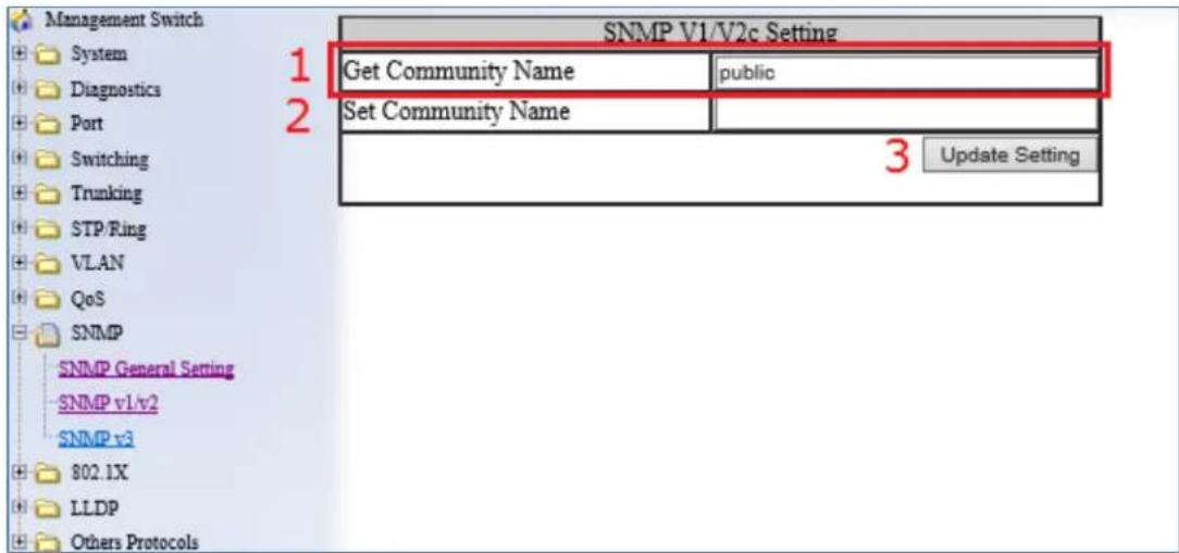
Figure 117: Community Name V1/V2c
Configuring SNMP v3 Users
To navigate to the SNMP v3 page:
- Click on the + next to SNMP.
- Click on SNMP v3.
Adding SNMP v3 Users to the switch
- Click on the Add User button. See below.

Figure 118: Add User
- Next, select the desired authentication/privacy protocols from the drop-down list next to "SNMP Version, according to the list below (also see Figure 119):
a. SNMPv3 No-Auth
b. SNMPv3 Auth-MD5
c. SNMPv3 Auth-SHA
d. SNMPv3 DES Auth-MD5
e. SNMPv3 DES Auth-SHA
f. SNMPv3 AES-128 Auth-MD5
g. SNMPv3 AES-192 Auth-MD5
h. SNMPv3 AES-256 Auth-MD5
i. SNMPv3 AES-128 Auth-SHA
j. SNMPv3 AES-192 Auth-SHA
k. SNMPv3 AES-256 Auth-SHA

Figure 119: SNMP v3 Settings
- Next, enter the desired username in the entry field next to User Name.
- Next, select the desired access authorization for the user from the drop-down list next to Access Mode. See Figure 120.

Figure 120: User name & Access Mode
- Next, if authentication is required for this user, and you have chosen an authentication protocol, then the entry field next to Auth. Password will have been enabled. Enter a password for this user inside this entry field. See Figure 121.

Figure 121: Auth Password
- Next, if both authentication and privacy are required for this user, and you have chosen both an authentication and privacy protocol, then the entry field next to Privacy PassPhrase will have been enabled. Enter a pass phrase inside this entry field, as part of the key used to encrypt the protocol message for this user. See Figure 122.
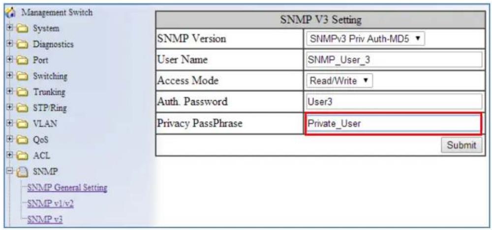
Figure 122: Privacy PassPhrase
Deleting SNMP v3 Users from the switch
- Go to SNMP → SNMP v3, you should see a list of previously configured users. Next, click on the Delete User button. See below.
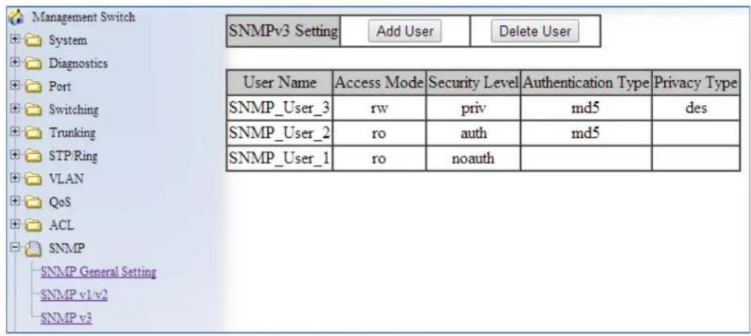
Figure 123: Delete User
- Next, select the user that you wish to delete from the drop-down list next to Select User Name.
- Click on the Submit button. See below.

Figure 124: Select User
SNMP Configuration Examples Using CLI Commands
For more information on CLI command usage see CLI Command Usage.
Enabling SNMP and configuring general settings
To enable the SNMP feature of the switch, and configure its general settings (Description, Location, and Contact information), use these CLI commands.:
CLI Command Mode: Global Configuration Mode
CLI Command Syntax:
snmp-server enable
snmp-server description <1 -256 characters>
snmp-server location <1 -256 characters>
snmp-server contact <1 -256 characters>
Usage Example:
switch_a> enable
switch_a#configure terminal
switch_a(config)# snmp-server enable
switch_a(config)# snmp-server description Hub_Switch_1
switch_a(config)# snmp-server location First_Floor_Closet
switch_a(config)# snmp-server contact Administrator
switch_a(config)#q
switch_a#
Configuring SNMP Traps
To configure the Trap features of the SNMP protocol on the switch, you use the following CLI commands:
CLI Command Mode:
Global Configuration Mode Interface Configuration Mode
CLI Command Syntax:
snmp-server trap-community 1 <1 -256 characters >
snmp-server trap-community 2 <1 -256 characters >
snmp-server trap-community 3 <1 -256 characters >
snmp-server trap-community 4 <1 -256 characters >
snmp-server trap-community 5 <1 -256 characters >
snmp-server trap-ipaddress 1 <IP Address>
snmp-server trap-ipaddress 2 <IP Address>
snmp-server trap-ipaddress 3 <IP Address>
snmp-server trap-ipaddress 4 <IP Address>
snmp-server trap-ipaddress 5 <IP Address>
snmp-server trap-type enable linkDown
snmp-server trap-type enable linkup
snmp-server trap-type enable mac-notification
snmp-server mac-notification interval <1 to 65535 seconds>
snmp-server mac-notification history-size <1 to 500 entries>
snmp-server trap mac-notification added
snmp-server trap mac-notification removed
Usage Example:
switch_a> enable
switch_a#configure terminal
switch_a(config)# snmp-server trap-community 1 Trap_Group_1
switch_a(config)# snmp-server trap-community 2 Trap_Group_2
switch_a(config)# snmp-server trap-community 3 Trap_Group_3
switch_a(config)# snmp-server trap-community 4 Trap_Group_4
switch_a(config)# snmp-server trap-community 5 Trap_Group_5
switch_a(config)# snmp-server trap-ipaddress 1 192.168.1.100
switch_a(config)# snmp-server trap-ipaddress 2 192.168.2.100
switch_a(config)# snmp-server trap-ipaddress 3 192.168.3.100
switch_a(config)# snmp-server trap-ipaddress 4 192.168.4.100
switch_a(config)# snmp-server trap-ipaddress 5 192.168.5.100
switch_a(config)# snmp-server trap-type enable linkDown
switch_a(config)# snmp-server trap-type enable linkup
switch_a(config)# snmp-server trap-type enable mac-notification
switch_a(config)# snmp-server mac-notification interval 60
switch_a(config)# snmp-server mac-notification history-size 100
switch_a(config)#interface fel
switch_a(config-if)#snmp-server trap mac-notification added
switch_a(config-if)#snmp-server trap mac-notification removed
switch_a(config-if)#q
switch_a(config)#q
switch_a#
Configuring SNMP v1 & v2 Community Groups
To configure the SNMP v1 & v2 community groups to make the SNMP feature more secure, use the following CLI commands:
CLI Command Mode: Global Configuration Mode
CLI Command Syntax: snmp-server enable snmp-server community get <1 -256 characters> snmp-server community set <1 -256 characters>
Usage Example:
switch_a> enable
switch_a#configure terminal
switch_a(config)# snmp-server community get public
switch_a(config)# snmp-server community set private
switch_a(config)#q
switch_a#
Adding SNMP v3 Users
To add SNMP v3 Users to the switch and maximize the security for the SNMP feature, you must use the following CLI commands:
CLI Command Mode: Global Configuration Mode
CLI Command Syntax:
snmp-server v3-user <username> <ro|rw> noauth
snmp-server v3-user <username> <ro|rw> auth <md5|sha> <password>
snmp-server v3-user <username> <ro|rw> priv <md5|sha> <password> des
<pass_phrase>
Usage Example:
switch_a> enable
switch_a#configure terminal
switch_a(config)# snmp-server v3-user SNMP_User_1 ro noauth
switch_a(config)# snmp-server v3-user SNMP_User_2 ro auth md5 User2
switch_a(config)# snmp-server v3-user SNMP_User_3 rw priv md5 User3
des Private_User
switch_a(config)#q
switch_a#
AAA/802.1X (AUTHENTICATION, AUTHORIZATION, AND ACCOUNTING)
EtherWAN switches support the IEEE 802.1X protocol to provide port based security on a switch port against unauthorized access. RADIUS and TACACS+ protocols are supported.
An EAP (Extensible Authentication Protocol) compatible RADIUS or TACACS+ server is required, as well as 802.1X client software (known as the “Supplicant” software) on the end device to communicate with the server for the purposes of authenticating the end device that is trying to gain access to the network through the switch port.
When an end device is initially connected to a port on the EtherWAN switch where the 802.1X protocol is enabled on the port, the switch will only pass 802.1X authentication traffic (known as EAPOL traffic) on that port between the Supplicant on the end device and the server, and will not allow any other traffic to pass. After the initial connection, the switch will request authentication credentials from the Supplicant in the end device that has just
connected to the port. After the switch receives the proper authentication credentials from the Supplicant in the end device, the switch will sent the credentials to the EAP compatible. If the end device is successfully authenticated by the server, the server will send a message to the switch.
Configuring Radius from the GUI
To navigate to the AAA / Radius Configuration page:
- Click on the + next to AAA
- Click on Radius Configuration
Enabling Radius
By default, the 802.1X function is globally disabled on the EtherWAN switch. If you want to use the 802.1X port based security on a port, you must enable it globally on the switch first, and then enable it on a per port basis.
To enable the 802.1X function globally on the switch:
- Choose enable from the drop down list next to Radius Status
- Click on the Update Setting button. (See Figure 125)
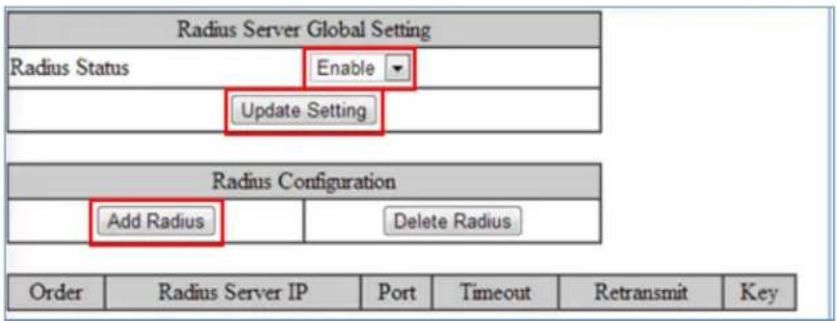
Figure 125: Enable Radius
Adding a Radius Server
Next, you will need to configure the settings that the switch will need in order to connect to a RADIUS server.
- Click on the Add Radius button (see above).
- Next, enter the IP address of the RADIUS server that the switch will use in order to authenticate in the entry field next to Radius Server IP (see Figure 126).
-
Enter the password for RADIUS server in the entry field next to Secret Key.
-
Optionally, the UDP port number for the RADIUS server (if it is different from the standard default 1812) can be changed. To do this, enter the port number in the entry field next to Radius Server Port.
-
Next, you can choose to configure the minimum time that the switch must wait, before it is allowed to retransmit a message to the RADIUS server due to no response. To do this, enter the number of seconds that the switch must wait (between 1 and 1000 seconds) into the entry field next to Timeout <1-1000>.
-
Next, you can choose to configure the maximum number of times that the switch can attempt to retransmit a message to the RADIUS server. To do this, enter a number (from 1 to 100) into the entry field next to Retransmit.
-
Click on the Submit button.

Figure 126: Radius Setup

Figure 127: Resulting Radius Server Setup
Enabling 802.1X on a Port
After the 802.1X port based security is enabled globally, you must enable it locally on the port.
To navigate to the 802.1X / Port Authentication page:
- Click on the + next to 802.1X
- Click on Port Authentication
To enable 802.1X on a port (see Figure 128):
- Choose the desired port from the drop-down list next to Interface, to have the 802.1X feature applied to that port.
- Next, make sure Enabled is selected from the drop-down list next to Authentication State, this will enable the 802.1X function on the previously selected port.
- Next, make sure that the choice Auto is selected in the drop-down list next to Port Control; this will allow the port to use 802.1X to authenticate the end station.
a. If you choose to have the port to be always unauthorized or to be always authorized, you can choose the appropriate choice in the drop-down list.
- Next, you can choose to have the end station to be re-authenticated periodically. To do this, choose Enabled in the drop-down list next to Periodic Re-authentication. Then select Enable or Disable for Reauthentication Period From Server.
- After you have enabled periodic re-authentication, you must also configure the time period interval for the re-authentication of the end station. To do this, enter the
number of seconds (1-4294967295), in to the entry field next to Re-authentication Period.
- Next, Update Setting button in order to activate all the configured settings (see the below screenshot)
| 802.1x Port Setting | |||||||
| Interface | fe1 ▼ | ||||||
| Authentication State | Enabled ▼ | ||||||
| Port Control | Auto ▼ | ||||||
| Periodic Reauthentication | Enabled ▼ | ||||||
| Reauthentication Period From Server | ○ Enable ● Disable | ||||||
| Reauthentication Period <1-4294967295> | 3600 | (sec.) | |||||
| Submit | |||||||
| Port | Port Enabled | Port Control | Port Status | Periodic Reauthentication | Reauthentication Period From Server | Reauthentication Period | |
| fe1 | |||||||
| fe2 | |||||||
| fe3 | |||||||
| fe4 | |||||||
Figure 128: Enabling 802.1X on a Port
Configuring TACACS+ from the GUI
To navigate to the AAA / TACACS+ Configuration page:
- Click on the + next to AAA
- Click on TACACS+
Enabling TACACS+
To enable TACACS+, set the Authorization State to Enable, and click Update Setting.

Figure 129: Enabling TACACS+
Adding a TACACS+ Server
Next, you will need to configure the switch to connect to a TACACS+ server. Setting a TACACS+ server to "primary" means that it will be the first server contacted when the switch tries to create a TACACS+ session. Only one server can be set to primary. Setting a TACACS+ server to "inactive" will disable it. A maximum of 3 servers can be added to a switch.
- In the TACACS Account button, select Create, or choose an existing server to modify.
- Enter the IP address of the TACACS server.
- Enter the server port.
- Enter the timeout value in seconds.
- Enter the secret key that will authenticate the switch to the TACAS server.
- Select Primary or Inactive for the server state. Inactive in this sense means "secondary," or "backup."
- Click on the Update button.

Figure 130: TACACS+ Setup
AAA/802.1x Configuration Using the CLI
For more information on CLI command usage see CLI Command Usage.
View RADIUS Status
Use the CLI commands below to view RADIUS statuses:
CLI Command Mode: User Exec Mode
CLI Command Syntax:
show dot1x
show dot1x all
show dot1x diagnostics interface
show dot1x interface
show dot1x sessionstatistics interface
show dot1x statistics interface
Enable RADIUS Globally
CLI Command Mode: Global Configuration Mode
CLI Command Syntax:
dot1x system-auth-ctrl
dot1x system-auth-ctrl disable
Configure RADIUS on Ports
CLI Command Mode: Interface Configuration Mode
CLI Command Syntax:
dot1x keytxenabled <enable | disable>
dot1x max-req <1-10>
dot1x port-control <force-unauthorized | force-authorized | auto>
dot1x port-control dir <in | both>
dot1x protocol-version <1-2>
dot1x quiet-period <1-65535>
dot1x reauthMax <1-10>
dot1x reauthentication
dot1x timeout re-authperiod <1-4294967295>
dot1x timeout server-timeout <1-65535>
dot1x timeout supp-timeout <1-65535>
dot1x timeout tx-period <1-65535>
Usage Example – Enabling and configuring RADIUS with host 10.1.1.100 and key "textkey."
Authentication is automatic:
switch_a>enable
switch_a#configure terminal
switch_a(config)#dot1x system-auth-ctrl
switch_a(config)#radius-server host 10.1.1.100 key textkey
switch_a(config)#interface fel
switch_a(config-if)#dot1x port-control auto
switch_a(config-if)#q
switch_(config)
Configure MAC-Based Authentication
MAC authentication uses the MAC address of the host for authentication. The RADIUS server has a dedicated host database that contains only allowed MAC addresses.
Use the CLI commands below to set up a mac-based authentication:
CLI Command Mode: Global Configuration Mode
CLI Command Syntax:
auth-mac <system-auth-control, username-format uppercase>
CLI Command Mode: Interface Configuration Mode
CLI Command Syntax:
auth-mac <enable, disable>
TACACS+ Authentication and Authorization
Use the CLI commands below to enable/disable TACACS+ for authentication:
CLI Command Mode: Global Configuration Mode
CLI Command Syntax:
(no) aaa authentication login tacplus
Use the CLI commands below to enable/disable TACACS+ for authorization:
CLI Command Mode: Global Configuration Mode
CLI Command Syntax:
(no) aaa authorization command tacplus
Configure TACACS+ Server
Setting a TACACS+ server to “primary” means that it will be the first server contacted when the switch tries to create a TACACS+ session. Only one server can be set to primary.
Setting a TACACS+ server to "inactive" will disable it. A maximum of 3 servers can be added to a switch.
Use the CLI commands below to set up a TACACS+ server:
CLI Command Mode: Global Configuration Mode
CLI Command Syntax:
(no) tacplus-server host hostname | IP address
Usage Example – Setting up a primary TACACS+ server with IP address 192.168.200.1 and secret key of "password1234" and a timeout of 3 minutes (180 seconds):
switch_a>enable
switch_a#configure terminal
switch_a(config)#aaa authentication login tacplus
switch_a(config)#tacplus-server host 192.168.200.1 key
password1234 timeout 180 primary
switch_a(config)
LLDP
LLDP is a network discovery protocol that defines a method for network access devices using Ethernet connectivity to advertise information about devices to peer devices on the same physical LAN and store information about the network. It allows a device to learn higher layer management reachability and connection endpoint information from adjacent devices.
Using LLDP, a device is able to advertise its own identification information, its capabilities and media-specific configuration information, as well as learn the same information from the devices connected to it. LLDP advertises this information over Logical Link-Layer Control frames and the information received from other agents in IEEE-defined Management Information Bases (MIB) modules.
LLDP significantly aids in the deployment of any network device that supports the protocol. As a media independent protocol intended to be run on all IEEE 802 devices, LLDP may be used to discover routers, bridges, repeaters, WLAN APs, IP telephones, network camera or any LLDP-enabled device, regardless of manufacturer. Since LLDP runs over the data-link layer only, a switch running one network layer protocol can discover and learn about an access device running a different network layer protocol.
LLDP General Settings
To navigate to the LLDP General Settings page:
- Click on the + next to LLDP.
- Click on General Settings.
Enable/Disable LLDP
To enable LLDP:
- Select Enable or Disable from the Drop Down box in the LLDP field of the LLDP Transmit Settings box (see Figure 131)
- Click on the Update Settings button.
- Save the configuration (see the Save Configuration Page)
Holdtime Multiplier
The Holdtime multiplier for transmit TTL is used to compute the actual time-to-live (TTL) value used in an LLDP frame. The TTL value is the length of time the receiving device should maintain the information in its MIB. To compute the TTL value, the system multiplies the LLDP transmit (TX) interval by the holdtime multiplier. For example, if the LLDP transmit (TX) interval is 30 and the holdtime multiplier for TTL is 4, then the value 120 is encoded in the TTL field in the LLDP header.
To adjust the Holdtime multiplier:
- Enter a numeric value between 2 and 10 (default is 4) in the Holdtime Multiplier text box.
- Click on the Update Settings button.
The TX Interval setting adjusts the time that LLDP information is transmitted by the switch. Values can range from 5 to 32768 seconds (default is 30 seconds).
To adjust the TX Interval setting (see Figure 131):
- Enter a numeric value between 5 and 32768 (default is 30) in the TX Interval text box.
- Click on the Update Settings button.
- Save the configuration (see the Save Configuration Page)
Global TLV Setting
The global TLV (Time – Length – Value) settings are advertised by the switch to other LLDP devices. The TLVs supported are (see Figure 131):
- Port Description
- System Name
- System Description
- System Capabilities
- Management Address
- Port VLAN ID
• MAC/PHY Configuration/Status
• Port And Protocol VLAN ID - VLAN Name
- Protocol Identity
- Power Via MDI
- Link Aggregation
• Maximum Frame Size
To enable specific TLVs on the switch:
-
Select the check box for each TLV that is to be enabled or select the checkbox for the AII option which will enable all TLVs for the switch.
-
Click on the Update Settings button.
- Save the configuration (see the Save Configuration Page)
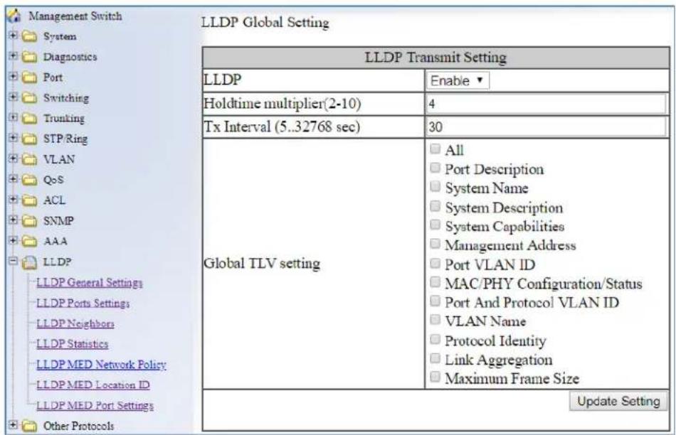
Figure 131: LLDP Global Settings
LLDP Ports Settings
LLDP Ports Settings allows the individual ports on the switch to be configured for LLDP independently of one another. Each port can be configured to transmit LLDP information, receive LLDP information, and notify (via SNMP or Syslog) if there are changes in the LLDP information received from neighboring devices.
To navigate to the LLDP Port Settings page:
- Click on the + next to LLDP.
- Click on LLDP Ports Settings (see Figure 132)
Enabling LLDP transmission for a specific Port
To enable the transmission of LLDP information for a specific port:
- Select Enable from the Drop Down box under the Transmit field for each port for which the transmission of LLDP information should be enabled.
- Click on the Submit button.
Enabling LLDP Reception for a specific Port
To enable the reception of LLDP information for a specific port:
- Select Enable from the Drop Down box under the Receive field for each port for which the reception of LLDP information should be enabled.
- Click on the Submit button.
Enabling Notifications
To enable notification whenever a port receives changed LLDP information:
- Select Enable from the Drop Down box under the Notify field for each port that should send a notification whenever received LLDP information changes.
- Click on the Submit button
- Save the configuration (see the Save Configuration Page) after making changes shown on this page.
| Port | Link Status | Transmit | Receive | Notify |
| 1 | Down | Disabled | Disabled | Disabled |
| 2 | Down | Disabled | Disabled | Disabled |
| 3 | Down | Disabled | Disabled | Disabled |
| 4 | Down | Disabled | Disabled | Disabled |
| 5 | Down | Disabled | Disabled | Disabled |
| 6 | Down | Disabled | Disabled | Disabled |
| 7 | Down | Disabled | Disabled | Disabled |
| 8 | Down | Disabled | Disabled | Disabled |
| 9 | Down | Disabled | Disabled | Disabled |
| 10 | Down | Disabled | Disabled | Disabled |
| 11 | Down | Disabled | Disabled | Disabled |
| 12 | Down | Disabled | Disabled | Disabled |
| 13 | Down | Disabled | Disabled | Disabled |
| 14 | Down | Disabled | Disabled | Disabled |
| 15 | Down | Disabled | Disabled | Disabled |
| 16 | Down | Disabled | Disabled | Disabled |
| 17 | Down | Disabled | Disabled | Disabled |
| 18 | Down | Disabled | Disabled | Disabled |
| 19 | Down | Disabled | Disabled | Disabled |
| 20 | Down | Disabled | Disabled | Disabled |
| 21 | Down | Disabled | Disabled | Disabled |
| 22 | Down | Disabled | Disabled | Disabled |
| 23 | Down | Disabled | Disabled | Disabled |
| 24 | Down | Disabled | Disabled | Disabled |
| 25 | Running | Disabled | Disabled | Disabled |
| 26 | Down | Disabled | Disabled | Disabled |
| 27 | Running | Disabled | Disabled | Disabled |
| 28 | Down | |||
Figure 132: LLDP Ports Settings
LLDP Neighbors
LLDP Neighbors is a read-only page (see Figure 133) that will display all the LLDP capable devices detected by the switch. The following information about connected LLDP-enabled devices is displayed in a tabular format. The columns displayed are:
- Port – The local switch port to which the remote device is connected.
- Chassis ID – The MAC address of the remote device.
- Port ID – The port number of the remote device.
- IP Address – The management IP address of the remote device.
- TTL – Time to Live, the amount time remaining before the remote device's LLDP is aged-out from the switch.
• MED type – Media endpoint discovery information
| Port | System Name | Chassis ID | Port ID | IP Address | TTL | MED type |
| fe1 | 3065.ec91.9820 | 3065.ec91.9820 | 0.0.0.0 | 2971 | Endpoint Class I |
Figure 133: LLDP Neighbors
LLDP Statistics
This is a read-only page (see Figure 134) that displays LLDP device statistics and LLDP statistics on a per-port basis. The information collected on this page includes:
- Port – switch port number.
• TX Total – Total LLDP packets sent. - RX Total – Total LLDP packets received.
- Discards – Number of LLDP packets discarded.
- Errors – LLDP errors.
- Ageout – LLDP information that has been aged out by the switch.
- TLV Discards – TLV information discarded
- TLV Unknown – TLV information that is unknown
| Management Switch System Diagnostics Port Switching Trunking STP/Ring VLAN QoS ACL SNMP 802.1X LLDP LLDP General Settings LLDP Ports Settings LLDP Neighbors LLDP Statistics Others Protocols | LLDP Device Statistics | |||||||
| Last Update | 130585126 | |||||||
| Total Inserts | 3 | |||||||
| Total Deletes | 0 | |||||||
| Total Drops | 0 | |||||||
| Total Ageouts | 0 | |||||||
| Port | Tx Total | Rx Total | Discards | Errors | Ageout | TLV Discards | TLV Unknowns | |
| 1 | 4 | 4 | 0 | 0 | 0 | 0 | 0 | |
| 2 | 0 | 0 | 0 | 0 | 0 | 0 | 0 | |
| 3 | 0 | 0 | 0 | 0 | 0 | 0 | 0 | |
| 4 | 0 | 0 | 0 | 0 | 0 | 0 | 0 | |
| 5 | 4 | 4 | 0 | 0 | 0 | 0 | 0 | |
| 6 | 0 | 0 | 0 | 0 | 0 | 0 | 0 | |
Figure 134: LLDP Statistics
LLDP MED Network Policy
Link Layer Discovery Protocol-Media Endpoint Discovery (LLDP-MED), improves information sharing between endpoints and network infrastructure devices. LLDP-MED
network policies let end-points and devices on the network to advertise the VLAN, priority levels, and DSCP values used by a voice or video application. Ports are assigned a network policy on the LLDP MED Port Settings page.
To create an LLDP Network Policy, enter the policy number (1 - 64), and select the application type:
guest-voice: Used when there is a separate voice network for visitors (guest users).
guest-voice-signaling: For when the network requires a separate policies for guest voice signaling and guest voice media.
softphone-voice: For softphone voice applications
streaming-video: For multicast video or other streaming video services that require a specific network policy
video-conferencing: For video conferencing applications.
video-signaling: Used to separate video signaling than for the video media. Do not use this application type if both the same network policies apply to both video and video signaling traffic.
voice: if the services, IP telephones, and other appliances support interactive voice services. This is the default application type.
voice-signaling: When there is a different policy for voice signaling than for voice media.
Do not use this application type if both the same network policies apply to both voice and voice signaling traffic.
Enter the VLAN Type, the VLAN ID, L2 Priority, and DSCP value. Then click Update Setting.
| Network Policy Configuration | |||||
| Network Policy Number(1~64) | Delete | ||||
| Application | guest-voice | ||||
| VLAN Type | Tag | ||||
| VLAN ID | 1 | ||||
| L2 Priority | 0 | ||||
| DSCP | 0 | ||||
| Update Setting | |||||
| Network Policy Number | Application | VLAN Type | VLAN ID | L2 Priority | DSCP Value |
Figure 135: LLDP MED Network Policy
LLDP MED Location ID
A wide array of location information can be configured for each port, and advertised to remote devices. This includes geographical coordinates, ELIN (emergency location identifier number) location, and physical address parameters. This information can be transmitted in calls, a feature especially important for calls to emergency services. All ports may be configured with the location of the switch, or each port may set up to read the location of the remote voice device connected to it.
| Location Identification List | ||
| Select | Type | Value |
| Delete | ||
| Coordinate Location | ||
| Latitude | ||
| Latitude Resolution | Default ▼ | |
| Longitude | ||
| Longitude Resolution | Default ▼ | |
| Altitude | Floors ▼ | |
| Altitude Resolution | Default ▼ | |
| Datum | WGS84 ▼ | |
| Submit | ||
| ELIN Location | ||
| ECS ELIN | ||
| Submit | ||
| Civic Address Location | ||
| Language | ||
| Script | ||
| Country | ||
| State/Province | Carrolwood | |
| County | Hillsborough | |
| City | Tampa | |
| City Division | ||
| Block/Neighborhood | ||
| Street Group | North Boulevard | |
| Leading Street Direction | ||
| Trailing Street Suffix | ||
| Street Suffix | ||
| House Number | 14906 | |
| House Number Suffix | ||
| Landmark | ||
| Additional Information | ||
| Name | ||
| Postal Code | 33612 | |
| Building | ||
| Unit | ||
| Floor | ||
| Room | ||
| Place Type | ||
| Postal Community Name | ||
| Postal Office Box | ||
| Additional Code | ||
| Seat | ||
| Primary Road Name | ||
| Road Section | ||
| Branch Road Name | ||
| Sub Branch Road Name | ||
| Street Name Pre Modifier | ||
| Street Name Post Modifier | ||
| Submit | ||
Figure 136: LLDP MED Location ID
Figure 137: LLDP MED Location ID
LLDP MED Port Settings
On this page you can assign which LLDP TLVs a specific port will use, and assing an optional policy.
| LLDP MED Port Status | |||
| Interface | User Defined Network Policy | TLVs | |
| NO. | Application | ||
| fe1 | -- | -- | inventory |
| fe2 | -- | -- | -- |
| fe3 | -- | -- | -- |
| fe4 | -- | -- | -- |
| fe5 | -- | -- | -- |
| fe6 | -- | -- | -- |
| fe7 | -- | -- | -- |
| fe8 | -- | -- | -- |
| fe9 | -- | -- | -- |
| fe10 | -- | -- | -- |
| fe11 | -- | -- | -- |
| fe12 | -- | -- | -- |
| fe13 | -- | -- | -- |
| fe14 | -- | -- | -- |
| fe15 | -- | -- | -- |
| fe16 | -- | -- | -- |
| ge1 | -- | -- | -- |
| ge2 | -- | -- | -- |
| LLDP MED Port Setting Table | |
| Interface: | fe1 ▼ |
| Optional TLVs | InventoryLocationNetwork Policy |
| Optional Policy | Guest Voice: -- ▼Guest Voice Signaling: -- ▼Softphone Voice: -- ▼Streaming Video: -- ▼Video Conferencing: -- ▼Video Signaling: -- ▼Voice: -- ▼Voice Signaling: -- ▼ |
LLDP Configuration Examples Using CLI Commands
For more information on CLI command usage see CLI Command Usage.
Enable/Disable LLDP
To enable or disable LLDP use the CLI commands below:
CLI Command Mode: Global Configuration Mode
CLI Command Syntax:
Ildp enable
no lldp enable
Usage Example – Enabling LLDP:
switch_a>enable
switch_a#configure terminal
switch_a(config)#lldp enable
switch_a(config)#q
switch_a#
Usage Example – Disabling LLDP:
switch_a>enable
switch_a#configure terminal
switch_a(config)#no lldp enable
switch_a(config)#q
switch_a#
LLDP Holdtime Multiplier
To modify LLDP holdtime multiplier use the CLI commands below:
CLI Command Mode: Global Configuration Mode
CLI Command Syntax: Ildp holdtime multiplier <1-10>
Usage Example:
switch_a>enable
switch_a#configure terminal
switch_a(config)#lldp holdtime multiplier 4
switch_a(config)#q
switch_a#
LLDP Transmit Interval
To modify LLDP Transmit Interval use the CLI commands below:
CLI Command Mode: Global Configuration Mode
CLI Command Syntax: Ildp txinterval <5-32768>
Usage Example:
switch_a>enable
switch_a#configure terminal
switch_a(config)# lldp txinterval 30
switch_a(config)#q
switch_a#
Enable/Disable Global LLDP TLVs
To enable or disable global LLDP TLVs use the CLI commands below:
CLI Command Mode: Global Configuration Mode
CLI Command Syntax: lldp tlv-global
TLV Parameters
| TLV Parameters | Description |
| port-descr | Port Description |
| sys-name | System Name TLV |
| sys-descr | System Description TLV |
| sys-cap | System Capabilities |
| mgmt-addr | Management Address |
| port-vlan-id | Port VLAN ID |
| mac-phy | MAC/PHY Configuration/Status |
| port-and-protocol | Port And Protocol VLAN ID |
| vlan-name | VLAN Name |
| protocol-identity | Protocol Identity |
| link-aggregation | (Link Aggregation |
| max-frame | Maximum Frame Size |
Usage Example:
switch_a>enable
switch_a#configure terminal
switch_a(config)# lldp tlv-global mgmt-addr
switch_a(config)#q
switch_a#
Enabling LLDP Transmit on a Port
To enable LLDP Transmit for a port use the CLI commands below:
CLI Command Mode: Interface Configuration Mode
CLI Command Syntax: lldp tx-pkt
Usage Example:
switch_a>enable
switch_a#configure terminal
switch_a#interface fel
switch_a(config)# lldp tx-pkt
switch_a(config)#q
switch_a#
Enabling LLDP Receive on a Port
To enable LLDP Receive for a port use the CLI commands below:
CLI Command Mode: Interface Configuration Mode
CLI Command Syntax: lldp rcv-pkt
Usage Example:
switch_a>enable
switch_a#configure terminal
switch_a#interface fel
switch_a(config)# lldp rcv-pkt
switch_a(config)#q
switch_a#
Enabling LLDP Notify
To enable LLDP Notify for a port use the CLI commands below:
CLI Command Mode: Interface Configuration Mode
CLI Command Syntax: lldp notification
Usage Example:
switch_a>enable
switch_a#configure terminal
switch_a#interface fel
switch_a(config)# lldp notification
switch_a(config)#q
switch_a#
Enabling Transmission of the Management IP
To enable the transmission of the management IP address through a port use the CLI commands below:
CLI Command Mode: Interface Configuration Mode
CLI Command Syntax: lldp mgmt-ip vlan
Usage Example:
switch_a>enable
switch_a#configure terminal
switch_a#interface fel
switch_a(config)# lldp mgmt-ip vlan 1
switch_a(config)#q
switch_a(config)#q
switch_a#
Enabling Specific TLV's on a Port
To enable specific TLVs on a port use the CLI commands below:
CLI Command Mode: Interface Configuration Mode
CLI Command Syntax: lldp tlv-select
Usage Example:
switch_a>enable
switch_a#configure terminal
switch_a#interface fel
switch_a(config)# lldp tlv-select mgmt-addr
switch_a(config)#q
switch_a#
Enabling LLDP MED TLV's on a Port
To enable MED TLVs on a port use the CLI commands below:
CLI Command Mode: Interface Configuration Mode
CLI Command Syntax: [no] lldp med-tlv-select
Usage Example:
switch_a>enable
switch_a#configure terminal
switch_a#interface fe1
switch_a(config)# lldp med-tlv-select location
switch_a(config)#q
switch_a#
Set LLDP-MED location information
To set LLDP MED location information, use the CLI commands below:
CLI Command Mode: Global Configuration Mode
CLI Command Syntax: [no] location civic-address [country-subdivision, county, city, city-division, country, block, street, leading-street-direction, trailing-street-suffix, street-suffix, number, number-suffix, landmark, location-information, name, zip, building, unit, floor, room, place-type, postal-community-name, post-box, additional-code, seat]
[no] location coordinate [latitude, longitude, altitude, alters, datum]
[no] location ecs-elin
Usage Example:
switch_a>enable
switch_a#configure terminal
switch_a(config)# location civic address Fryeburg
switch_a(config)#q
switch_a#
OTHER PROTOCOLS
GVRP
Defined in IEEE 802.1Q, GVRP is a protocol used to dynamically create VLANs on a switch. Any IEEE 802.1Q compliant switch must implement this protocol.
To navigate to the Other Protocols / GVRP page (see Figure 138):
- Click on the + next to Other Protocols.
- Click on GVRP.

Figure 138: GVRP
General Overview
To enable the GVRP protocol on your network, you must make sure that the switches in your network are configured with the minimum requirements for each type of switches listed below:
For the Access Switches at the edge of the network, below are the minimum requirements:
- All of the user VLANs have been created in the VLAN Database.
-
The IP address for the Management VLAN has been configured.
-
The appropriate Port Type (Access or Trunk) and the PVID have been configured for all the ports of the switch.
- All the member Trunk ports for all the user VLANs have been configured.
- The GVRP protocol has been globally enabled, and GVRP is locally enabled on the Trunk Ports as well.
For the Distribution Switches in the core of the network, below are the minimum requirements:
- The Management VLAN has been created in the VLAN Database.
- The IP address for the Management VLAN has been configured.
- The appropriate Port Type (Access or Trunk) and the PVID have been configured for all the ports of the switch.
- The GVRP protocol has been globally enabled and GVRP is locally enabled on the Trunk Ports as well.
- The Dynamic VLAN Creation feature has been enabled.
Enabling the GVRP Protocol at the Global Level
To enable the GVRP protocol globally on a distribution switch (see Figure 139):
- Under GVRP Global Setting, choose the Enable option from the drop-down list next to GVRP.
- Choose the Enable option from the drop-down list next to Dynamic VLAN Creation.
- Click on the Update Setting button.

Figure 139: GVRP Configuration Distribution Switch
To enable the GVRP protocol globally on an Access Switch (see Figure 140):
- Under GVRP Global Setting, choose the Enable option from the drop-down list next to GVRP.
- Click on the Update Setting button.
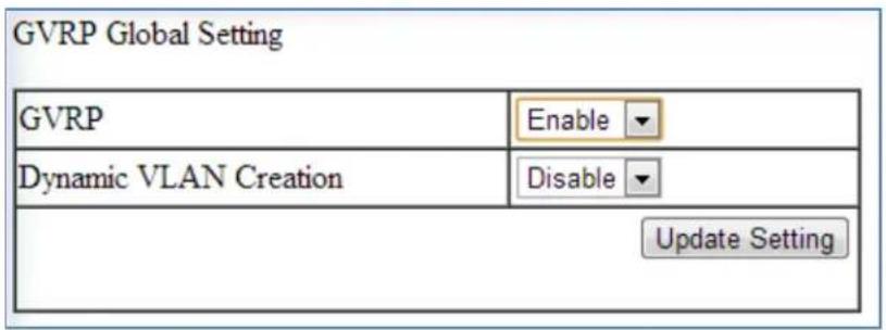
Figure 140: GVRP Configuration Access Switch
Enabling the GVRP Protocol at the Port Level
To navigate to the Other Protocols / GVRP page (see Figure 138):
- Click on the + next to Other Protocols.
- Click on GVRP.
To enable the GVRP protocol locally at the port level, for both the Access switch and the Distribution switch, apply the following procedures to all the Trunk Ports of the switch:
- For all the Trunk Ports under the Per Port Setting (include LAG) section, choose the Enable option from the drop-down list under the GVRP column.
- For all the Trunk Ports under the Per Port Setting (include LAG) section, choose the Active or Normal option from the drop-down list under the GVRP Applicant column.
Active - Use this option if you want to run the GVRP protocol on that Trunk Port even if it is blocked by the STP protocol.
Normal – Use this option if you do not wish to run the GVRP protocol on a Trunk Port when it is being blocked by the STP protocol.
- For all the Trunk Ports under the Per Port Setting (include LAG) section, choose the Enable option from the drop-down list under the GVRP Registration column.
- Click on the Update Setting button.
- Save the configuration (see the Save Configuration Page)
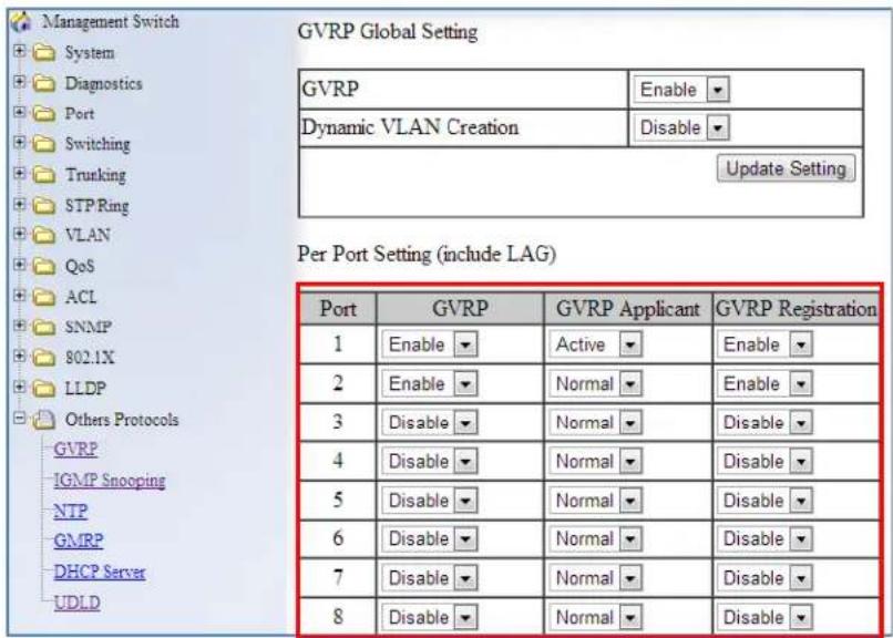
Figure 141: GVRP Per Port Settings
GVRP Configuration Examples Using CLI Commands
For more information on CLI command usage see CLI Command Usage.
To enable or disable GVRP globally on the EtherWAN switch, use the following CLI commands:
CLI Command Mode: Global Configuration Mode
CLI Command Syntax:
set gvrp enable bridge 1
set gvrp disable bridge 1
Usage Example:
switch_a>enable
switch_a#configure terminal
switch_a(config)# set gvrp enable bridge 1
switch_a(config)# set gvrp disable bridge 1
switch_a(config)#q
switch_a#
To enable the dynamic VLAN creation feature of GVRP on the EtherWAN switch, you must use the following CLI commands:
CLI Command Mode: Global Configuration Mode
CLI Command Syntax: set gvrp dynamic-vlan-creation disable bridge 1
Usage Example:
switch_a>enable
switch_a#configure terminal
switch_a(config)# set gvrp dynamic-vlan-creation disable bridge 1
switch_a(config)#q
switch_a#
To enable or disable GVRP locally on a port on the EtherWAN switch, you must use the following CLI commands:
CLI Command Mode: Global Configuration Mode
CLI Command Syntax:
set port gvrp enable
Usage Example:
switch_a>enable
switch_a#configure terminal
switch_a(config)# set port gvrp enable fe1
switch_a(config)# set port gvrp disable fe1
switch_a(config)#q
switch_a#
By default, when GVRP is enabled on a port the Applicant runs in Normal mode, which means that the GVRP protocol will not send out any PDUs from a port if the port is being blocked by STP. When you enable the GVRP Applicant to run in Active mode on a port, the GVRP protocol will continue to send PDUs from a port even if the port is being blocked by STP.
The GVRP Applicant can be set to run in Normal or Active mode on a port by issuing the following CLI commands:
CLI Command Mode: Global Configuration Mode
CLI Command Syntax:
set gvrp applicant state normal
Usage Example:
switch_a>enable
switch_a#configure terminal
switch_a(config)# set gvrp applicant state normal fel
switch_a(config)# set gvrp applicant state active fel
switch_a(config)#q
switch_a#
When you enable GVRP on a port, the Registrar is enabled on the port by default. You can enable or disable the GVRP Registrar on a port by issuing the following CLI commands:
CLI Command Mode: Global Configuration Mode
CLI Command Syntax:
set gvrp registration normal
set gvrp registration forbidden
Usage Example:
switch_a>enable
switch_a#configure terminal
switch_a(config)# set gvrp registration normal fel
switch_a(config)# set gvrp registration forbidden fel
switch_a(config)#q
switch_a#
IGMP Snooping
The settings in the IGMP Snooping feature of the EtherWAN switch controls how the switch forwards multicast packets.
General Overview
The switch is equipped with the IGMP Snooping function in three modes:
- Disabled:
- The switch will forward all multicast packets according to the Forced Forwarding Port setting based on the following rule:
- All multicast packets will be forwarded to only the port specified by either the PassiveForwardMode or the ForcedForwardMode function.
- Passive mode:
- The switch will forward any multicast packets that have known receivers to the known multicast receiver ports only.
- The switch will forward any unknown multicast packets (multicast packets without any known receivers) according to the Forced Forwarding Port setting based on the following rule:
- When there is no Querier Port (a port that receives IGMP queries) present all unknown multicast packets will be forwarded to the port specified by either the PassiveForwardMode function or the ForcedForwardMode function.
- When there is a Querier port present, the switch will forward all unknown multicast packets to the Querier port. In addition, all unknown multicast packets will be forwarded to the port specified by the ForcedForwardMode function as well.
- Querier mode:
- The switch will forward any multicast packets that have known receivers to the known multicast receiver ports only.
- The switch will forward any unknown multicast packets according to the Forced Forwarding Port setting based on the following rule:
- All unknown multicast packets will be sent to only the port specified by the ForcedForwardMode function.
- The switch will also transmit IGMP Queries to the specified VLAN and according to the specified IGMP Query parameters.
Enabling the IGMP Snooping Modes
To navigate to the IGMP Snooping page:
- Click on the + next to Other Protocols.
- Click on IGMP Snooping.
To put the IGMP Snooping feature in the correct Mode, follow the steps below:
- Choose the appropriate choice from the dropdown list next to IGMP mode
- Click on the Update Setting button (See below)

Figure 142: IGMP Mode
Configuring IGMP Snooping General properties
To navigate to the IGMP Snooping page:
- Click on the + next to Other Protocols.
- Click on IGMP Snooping.
To configure the general features for IGMP Snooping in either the Passive or Querier mode, follow the steps below (see Figure 143):
- From the dropdown list next to VLAN ID, choose the VLAN that you want the IGMP Snooping process to run on.
- From the dropdown list next to IGMP Version, choose the correct IGMP version to be run on this VLAN. This setting must match the IGMP version being used by the IGMP querier and the IGMP client on the network.
- Choosing the appropriate choice (Enable or Disable) from the dropdown list next to Fast Leave.
- If this feature is enabled on the switch, and the switch receives a request to leave a multicast stream on a port, then the switch will drop this multicast stream on that port without checking to see if there are any other multicast clients on that port that might still be interested in receiving this multicast stream. This allows the multicast stream to disappear from a port much faster.
- Next, click on the Update Setting button

Figure 143: IGMP General Properties
Configuring IGMP Passive Mode Specific properties
To navigate to the IGMP Snooping page:
- Click on the + next to Other Protocols.
- Click on IGMP Snooping.
To configure specific properties for IGMP Passive Mode, follow the steps below.

Figure 144: IGMP Passive Mode
- From the dropdown list next to VLAN ID, choose the VLAN for which you wish to configure the Report Suppression feature.
- Choose Enable or Disable in the dropdown list next to Report Suppression. (Note: if the switch is not in Passive mode, then this feature will have no effect.)

Note: If you are using IGMP version 1 or 2, the Query Interval, and the Max
Response Time setting must be configured even if you are not configuring IGMP Querier mode. For IGMP version 1 and 2, the membership registration timer (used to time out the membership status on each port) is based on these two parameters on the local switch. These two parameters should configure to match that of the current active IGMP Querier. The formula for the membership registration timer is: 2 X query-interval + max-response-time = Timeout period.
Configuring IGMP Querier Mode Specific properties
To navigate to the IGMP Snooping page:
- Click on the + next to Other Protocols.
- Click on IGMP Snooping.
To configure specific properties for IGMP Querier Mode, follow the steps below (see Figure 145):
- In the text box next to Query Interval, enter a value between 10 and 18000
- This value will represent the time interval, in seconds, between any two queries that the switch scents on to the network. It is recommended that you use the default setting of 125 seconds that are according to the IGMP standard.
- In the text box next to Max Response Time, enter a value between 1 and 240.
- This value represents the maximum time in seconds that a multicast client will have to respond to an IGMP query. Any response received after this time will not be accepted by the Querier. It is recommended that you use the default setting of 10 seconds according to the IGMP standard.

Figure 145: Querier Mode Properties
Configuring IGMP Unknown Multicast Forwarding
To navigate to the IGMP Snooping page:
- Click on the + next to Other Protocols.
- Click on IGMP Snooping.
With IGMP enabled, the EtherWAN switch will transmit all multicast packets to their only multicast receiver ports. However, some multicast packets will not have any known multicast receiver ports either due to IGMP Snooping being disabled on the switch, or because no multicast receiver has sent IGMP requests for these multicast packets. The multicast packets in these scenarios are referred to as unknown multicast packets. You can use the Passive Mode Forwarding Port section of the IGMP Snooping configuration page to control how the switch will forward these unknown multicast packets under different IGMP Snooping modes of the switch (see Figure 146).
Disabled Mode Forwarding Port Configuration
When IGMP is in Disabled Mode, all multicast packets are unknown multicast packets, and by default all unknown multicast packets are forwarded to all the ports of the switch. To modify the default behavior and to control how the switch will forward unknown multicast packets when the switch is in IGMP Snooping Disabled mode:
- Select either the PassiveForwardMode or the ForceForwardMode radio button.
- Make sure that only the ports that you would like to have the unknown multicast packets to be forwarded to, have a check mark next to it.
- Then click on the Update Setting button.

Figure 146: Disabled Mode Forwarding Port
Passive Mode Forwarding Port Configuration
You can control how the switch forwards unknown multicast packets under IGMP Passive mode in two different conditions:
- When there is no IGMP Querier port (a port that receives IGMP queries) present.
- When an IGMP Querier port is present or when no IGMP Querier port is present.
To configure how the switch forwards unknown multicast packets when the switch is in IGMP Passive mode, follow the steps below:
No IGMP Querier port present
- Under the Passive Mode Forwarding Port section, select the PassiveForwardMode radio button.
- Select the checkbox under the ports that you would like to have the unknown multicast packets forwarded to.
- Click on the "Update Setting" button.

Note: The presence of an IGMP Querier port will make the settings provided by PassiveForwardMode to have no effect, and all unknown multicast packets will forwarded to the IGMP Querier port only.
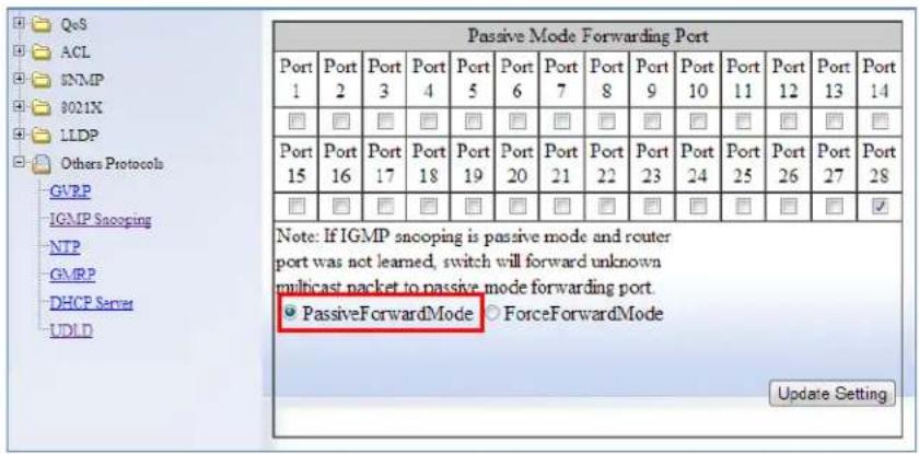
Figure 147: PassiveForwardMode
IGMP Querier port present or no IGMP Querier port present
- Under the Passive Mode Forwarding Port section, select the ForceForwardMode radio button
- Select the checkbox under the ports that you would like to have the unknown multicast packets forwarded to.
- Click on the Update Setting button.
Note: The settings according to the ForceForwardMode will always be in effect both with and without the presence of an IGMP Querier port. In addition, when an IGMP Querier port is present, all unknown multicast packets will also be forwarded to the IGMP Querier port as well, in addition to the settings in the ForceForwardMode function.

Figure 148: ForceForwardMode
IGMP Querier Mode Forwarding Port Configuration
To configure how the switch forwards unknown multicast packets when the switch is in IGMP Querier mode, follow the below instructions:
- Under the Passive Mode Forwarding Port section, select the ForceForwardMode radio button
- Select the checkbox under the ports that you would like to have the unknown multicast packets forwarded to.
- Click on the Update Setting button.

Note: When the switch is in IGMP Snooping Querier mode, there will not be IGMP Querier port present, and the settings according to the ceForwardMode will always be in effect.

Figure 149: IGMP Querier Mode Forwarding
Monitoring Registered Multicast Groups
To navigate to the Multicast Current Table page:
- Click on the + next to Other Protocols.
- Click on IGMP Snooping.
- Click on the Multicast Current Table link at the top of the page.
When the switch is in IGMP Passive or IGMP Querier mode, registered Multicast Groups can be monitored on each port, as well as the location of the IGMP Querier port (see Figure 150).
- All the registered multicast Groups will be listed in the Group Address column.
- The port where each registered Group ID was received can be found in the Membership column in each registered Groups corresponding row.

Note: when an IGMP Querier port is present, all registered multicast group IDs will v up in the Membership column as a checked box for the IGMP Querier port, even if IGMP Join was never received for that Group ID on the Querier port.

Figure 150: Current Multicast Groups
IGMP Configuration Examples Using CLI Commands
For more information on CLI command usage see CLI Command Usage.
To put the IGMP Snooping feature in Disabled Mode use the CLI commands below:
CLI Command Mode: Global Configuration Mode
CLI Command Syntax: no ip igmp snooping
Usage Example:
switch_a>enable
switch_a#configure terminal
switch_a(config)#no ip igmp snooping
switch_a(config)#q
switch_a#
To put the IGMP Snooping feature in Passive Mode use the CLI commands below:
CLI Command Mode: Global Configuration Mode
CLI Command Syntax: ip igmp snooping enable no ip igmp snooping querier
Usage Example:
switch_a>enable
switch_a#configure terminal
switch_a(config)#ip igmp snooping enable
switch_a(config)#no ip igmp snooping querier
switch_a(config)#q
switch_a#
To put the IGMP Snooping feature in Querier Mode use the following CLI commands:
CLI Command Mode: Global Configuration Mode
CLI Command Syntax: ip igmp snooping enable ip igmp snooping querier
Usage Example:
switch_a>enable
switch_a#configure terminal
switch_a(config)#ip igmp snooping enable
switch_a(config)#ip igmp snooping querier
switch_a(config)#q
switch_a#
To set the IGMP version per VLAN, use the following CLI commands:
CLI Command Mode: Global Configuration Mode
CLI Command Syntax: ip igmp version <1-3>
Usage Example:
switch_a>enable
switch_a#configure terminal
switch_a(config)#interface vlan1.1
switch_a(config-if)#ip igmp version 2
switch_a(config-if)#q
switch_a(config)#
To enable or disable the IGMP fast-leave feature on a VLAN, use the CLI commands below:
CLI Command Mode: VLAN Interface Configuration Mode
CLI Command Syntax: ip igmp snooping fast-leave no ip igmp snooping fast-leave
Usage Example - Enabling the IGMP fast-leave feature:
switch_a>enable
switch_a#configure terminal
switch_a(config)#interface vlan1.1
switch_a(config-if)#ip igmp snooping fast-leave
switch_a(config-if)#q
switch_a(config)#
Usage Example - Disabling the IGMP fast-leave feature:
switch_a>enable
switch_a#configure terminal
switch_a(config)#interface vlan1.1
switch_a(config-if)#no ip igmp snooping fast-leave
switch_a(config-if)#q
switch_a(config)#
To enable or disable the IGMP Report Suppression feature on a VLAN, use the CLI commands below:
CLI Command Mode: VLAN Interface Configuration Mode
CLI Command Syntax:
ip igmp snooping report-suppression
no ip igmp snooping report-suppression
Usage Example - Enabling the IGMP Report Suppression feature:
switch_a>enable
switch_a#configure terminal
switch_a(config)#interface vlan1.1
switch_a(config-if)# ip igmp snooping report-suppression
switch_a(config-if)#q
switch_a(config)#
Usage Example - Disabling the IGMP Report Suppression feature:
switch_a>enable
switch_a#configure terminal
switch_a(config)#interface vlan1.1
switch_a(config-if)#no ip igmp snooping report-suppression
switch_a(config-if)#q
switch_a(config)#
To configure the IGMP query-interval, and the max-response-time settings per VLAN, use the CLI commands below:
CLI Command Mode: VLAN Interface Configuration Mode
CLI Command Syntax:
ip igmp query-interval <10-18000>
ip igmp query-max-response-time <1-240>
Usage Example - Configuring the IGMP query-interval parameter:
switch_a>enable
switch_a#configure terminal
switch_a(config)#interface vlan1.1
switch_a(config-if)# ip igmp query-interval 125
switch_a(config-if)#q
switch_a(config)#
Usage Example - Configuring the IGMP max-response-time parameter:
switch_a>enable
switch_a#configure terminal
switch_a(config)#interface vlan1.1
switch_a(config-if)#ip igmp query-max-response-time 10
switch_a(config-if)#q
switch_a(config)#
To control how the switch forwards unknown multicast packets when the switch is in IGMP Disabled mode, follow the instructions below:
CLI Command Mode: Global Configuration Mode
CLI Command Syntax:
ip igmp snooping passive-forward all
ip igmp snooping passive-forward none
ip igmp snooping passive-forward
Usage Example - Flood all unknown multicast packets:
switch_a>enable
switch_a#configure terminal
switch_a(config)# ip igmp snooping passive-forward all
switch_a(config)#q
Usage Example - Drop all unknown multicast packets:
switch_a>enable
switch_a#configure terminal
switch_a(config)# ip igmp snooping passive-forward none
switch_a(config)#q
Usage Example - Forward unknown multicast packets to the specified ports only:
switch_a>enable
switch_a#configure terminal
switch_a(config)# ip igmp snooping passive-forward fe1,fe2,fe3
switch_a(config)#q
To only control how the switch will forward unknown multicast packets when the switch is in IGMP Passive mode and also without a Querier Port present, follow the below instructions:
CLI Command Mode: Global Configuration Mode
CLI Command Syntax:
ip igmp snooping passive-forward all
ip igmp snooping passive-forward none
ip igmp snooping passive-forward
Usage Example - Flood all unknown multicast packets:
switch_a>enable
switch_a#configure terminal
switch_a(config)# ip igmp snooping passive-forward all
switch_a(config)#q
switch_a#
Usage Example - Drop all unknown multicast packets:
switch_a>enable
switch_a#configure terminal
switch_a(config)# ip igmp snooping passive-forward none
switch_a(config)#q
switch_a#
Usage Example - Forward unknown multicast packets to the specified ports only:
switch_a>enable
switch_a#configure terminal
switch_a(config)# ip igmp snooping passive-forward fe1,fe2,fe3
switch_a(config)#q
switch_a#
To control how the switch will forward unknown multicast packets when the switch is in IGMP Passive mode, both with or without a Querier Port present, follow the instructions below:
CLI Command Mode: Global Configuration Mode
CLI Command Syntax:
ip igmp snooping force-forward all
ip igmp snooping force-forward none
ip igmp snooping force-forward
Usage Example - Flood all unknown multicast packets:
switch_a>enable
switch_a#configure terminal
switch_a(config)# ip igmp snooping force-forward all
switch_a(config)#q
switch_a#
Usage Example - Drop all unknown multicast packets:
switch_a>enable
switch_a#configure terminal
switch_a(config)# ip igmp snooping force-forward none
switch_a(config)#q
switch_a#
Usage Example - Forward unknown multicast packets to the specified ports only:
switch_a>enable
switch_a#configure terminal
switch_a(config)# ip igmp snooping force-forward fe1,fe2,fe3
switch_a(config)#q
switch_a#
To control how the switch will forward unknown multicast packets when the switch is in IGMP Querier mode, follow the below instructions:
CLI Command Mode: Global Configuration Mode
CLI Command Syntax:
ip igmp snooping force-forward all
ip igmp snooping force-forward none
ip igmp snooping force-forward <ifname>,<ifname>,<ifname>
Usage Example - Flood all unknown multicast packets:
switch_a>enable
switch_a#configure terminal
switch_a(config)# ip igmp snooping force-forward all
switch_a(config)#q
switch_a#
Usage Example - Drop all unknown multicast packets:
switch_a>enable
switch_a#configure terminal
switch_a(config)# ip igmp snooping force-forward none
switch_a(config)#q
switch_a#
Usage Example - Forward unknown multicast packets to the specified ports only:
switch_a>enable
switch_a#configure terminal
switch_a(config)# ip igmp snooping force-forward fe1,fe2,fe3
switch_a(config)#q
switch_a#
Network Time Protocol (NTP)
NTP or Network Time Protocol is a useful tool designed to update your switch with the most accurate time available from a user specified time source. This is useful for the end user in that the switch logging is noted with the actual time rather than the default switch time (begins on Jan 1st, 2010) as it can aid debugging switching related problems by showing an accurate time an event occurred.
To navigate to the NTP page:
- Click on the + next to Other Protocols.
- Click on NTP
Setting RTC Time
(Only applicable to certain models) At the top of this screen, there are fields in which you can enter the current year, date, and time. When done, click Update Setting to make the time change take effect. (See figure below) Note that the time will reset whenever the switch is rebooted, or restarted after a power loss.
| Adjust RTC Time | |||||||
| Year(2000-2037): 2016 | Month: 8 | Day: 8 | Mon | Hour: 17 | Minute: 4 | Second: 39 | |
| Update Setting | |||||||
To manually set the time using the CLI:
CLI Command Mode: Privileged exec mode
CLI Command Syntax: set clock <2000-2037> <1-12> <1-31> <0-23> <0-59> <0-59>
Usage Example:
switch_a>enable
switch_a# set clock 2019 3 27 17 24 30
Enabling NTP
To enable the NTP client, follow the steps below (see Figure 151):
- Choose Enable from the dropdown list next to NTP Status
- Click on the Update Setting button
Setting the NTP Server IP Address
To provide a time source for the NTP client, follow the steps below:
- Enter an IP address or host name in the NTP Server text box.
- Click on the Update Setting button
Setting the Time Zone
To change the time zone of the switch, follow the steps below:
-
Select the proper time zone from the dropdown list next to Time Zone.
-
Click on the Update Setting button
Setting the Polling Period
To alter the polling period (how often the NTP client checks the server for the correct time), follow the steps below:
- Enter the new polling period in the Polling Interval textbox.
- Click on the Update Setting button
Manually Syncing Time
To set the time immediately using an NTP server, follow the steps below:
- Enter the new polling period in the Polling Interval textbox.
- Click on the Sync Time button in the NTP Server field

Figure 151: NTP Settings
Daylight Savings Time - Weekday Mode
To adjust the switch's clock for Daylight Savings Time using the weekday mode, follow the steps below:
- Select the option Weekday from the Daylight Saving Mode dropdown box.
- Enter the value for the time offset in the Time Set Offset textbox.
-
Enter the name of the Daylight Saving Time Zone.
-
In the Weekday Box, select the month, week, day, hour, and minute for both the from and to fields. For example, if Daylight Saving Time begins on the second Sunday in March at 2:00AM and ends on the first Sunday in November at 2:00AM, then select the values as shown in Figure 152.
-
Click on the Update Setting button
| Daylight Saving Setting | |
| Daylight Saving Mode | Weekday |
| Time Set Offset (1-480 min) | 60 |
| Name of Daylight Saving Timezone | CDT |
| Weekday From To | Month Mar 2 Week 2 Day Sun Hour 2 Minute 0 Month Nov 1 Day Sun Hour 2 Minute 0 |
| Date From To | Month Jan Day Hour Month Jan Day Hour Minute |
| Update Setting | |
Figure 152: Daylight Savings – Weekday Mode
Daylight Savings Time – Date Mode
To adjust the switch's clock for Daylight Savings Time using the date mode, follow the steps below:
- Select the option Date from the Daylight Saving Mode dropdown box.
- Enter the value for the time offset in the Time Set Offset textbox.
-
Enter the name of the Daylight Saving Time Zone.
-
In the Date section, select the month and enter the date, hour, and minute for both the from and to fields. For example, if Daylight Saving Time begins on March 9th at 2:00AM and ends on November 2nd at 2:00AM, then select the values as shown in Figure 153.
-
Click on the Update Setting button
| Daylight Saving Setting | |
| Daylight Saving Mode | Date |
| Time Set Offset (1-480 min) | 60 |
| Name of Daylight Saving Timezone | CDT |
| Weekday From To | Month Jan Week Day Sun Hour Minute Month Jan Week Day Sun Hour Minute |
| Date From To | Month Mar Day 9 Hour 2 Minute 0 Month Nov Day 2 Hour 2 Minute 0 |
| Update Setting | |
Figure 153: Daylight Savings – Date Mode
Network Time Protocol Configuration Examples Using CLI Commands
For more information on CLI command usage see CLI Command Usage.
To enable NTP, use the CLI commands below:
CLI Command Mode: Global Configuration Mode
CLI Command Syntax: ntp enable
Usage Example:
switch_a>enable
switch_a#configure terminal
switch_a(config)#ntp enable
switch_a(config)#q
To set the NTP server, use the CLI commands below. Multiple (up to 2) NTP servers can be configured
CLI Command Mode: Global Configuration Mode
CLI Command Syntax: ntp server
Usage Example:
switch_a>enable
switch_a#configure terminal
switch_a(config)#ntp server 192.168.1.126
To set the NTP polling interval, use the CLI commands below:
CLI Command Mode: Global Configuration Mode
CLI Command Syntax: ntp polling-interval
Usage Example:
switch_a>enable
switch_a#configure terminal
switch_a(config)#ntp polling-interval 180
switch_a(config)#q
switch_a#
To have the NTP client sync the clock immediately, use the CLI commands below:
CLI Command Mode: Global Configuration Mode
CLI Command Syntax: ntp sync-time
Usage Example:
switch_a>enable
switch_a#configure terminal
switch_a(config)#ntp sync-time
switch_a(config)#q
switch_a#
Show system uptime:
CLI Command Mode: Privileged Exec Mode
CLI Command Syntax: show system-uptime
Usage Example:
switch_a>#show system-uptime
To set the current time, use the CLI commands below:
CLI Command Mode: Global Configuration Mode
CLI Command Syntax:
clock timezone
Usage Example:
switch_a>enable
switch_a#configure terminal
switch_a(config)#clock timezone CDT -6:00
switch_a(config)#q
switch_a#
To set the Daylight Savings Time settings using weekday mode, use the CLI commands below:
CLI Command Mode: Global Configuration Mode
CLI Command Syntax:
clock summer-time
Usage Example:
switch_a>enable
switch_a#configure terminal
switch_a(config)# clock summer-time CDT weekday 2 Sun March 201 Sun November 2060
switch_a(config)#q
switch_a#
To set the Daylight Savings Time settings using date mode, use the CLI commands below:
CLI Command Mode: Global Configuration Mode
CLI Command Syntax:
clock summer-time
Usage Example:
switch_a>enable
switch_a#configure terminal
switch_a(config)# clock summer-time CDT date 9 March 2 0 2 November 2 0 60
switch_a(config)#q
switch_a#
GMRP
The settings in the GMRP feature controls how the switch automates the process of multicast packet forwarding, both within a single switch as wells as between switches in a bridged network. With the GMRP feature enabled, when the switch receives any GMRP multicast group registration requests from either a multicast client or a neighbor switch, the switch will register these multicast groups on these ports and will only transmit the multicast packets that belong to these groups to these ports. The switch will also automatically propagate these multicast group registrations onto the neighbor switches to allow the neighbor switches to forward the multicast packets that belong to these groups to the local switch.
To navigate to the Other Protocols / GMRP page:
- Click on the + next to Other Protocols.
- Click on GMRP.
General Overview
The ports on the EtherWAN switch can be configured with the GMRP feature in five modes:
- Disabled
- Normal
- Fixed
- Forbidden
- Forward All.
GMRP Normal mode
When a port is put in GMRP Normal mode, that port can accept both multicast group registration and multicast group deregistration from the multicast client or the neighbor switch that is residing on that port. Also, the switch will propagate all the registered multicast groups on the switch to the neighbor switch residing on that port.
GMRP Fixed mode
When a port is put in GMRP Fixed mode, that port can accept group registration but will not accept any group deregistration from multicast clients or neighbor switches that reside on that port. Also, the switch will be propagating all the registered multicast groups on the switch to the neighbor switch residing on that port.
GMRP Forbidden mode
When a port is put in GMRP Forbidden mode, all multicast groups will be deregistered on that port and that port will not be accepting any further multicast group registrations. However, the switch will still be propagating all the registered multicast groups on the switch to the neighbor switch residing on that port.
GMRP Forward All mode
When a port is put in GMRP Forward All mode, all the registered multicast groups on the switch will automatically be registered to this port, so the switch will be forwarding all the multicast packets that belong to these groups to this port and this port will also be propagating all the registered multicast groups on the switch to the neighbor switch residing on that port.
GMRP Disabled mode
When a port is put in GMRP disabled mode that port will not participate in any GMRP activities.
Enabling the GMRP Feature Globally on the Switch
To navigate to the Other Protocols / GMRP page:
- Click on the + next to Other Protocols.
- Click on GMRP.
To enable the GMRP function in the switch, follow the procedure below:
- Choose the Enable option from the dropdown list next to GMRP
- Click on the Update Setting button. (See Figure 154)

Figure 154: GMRP Global Setting
Configuring the GMRP Feature Per Port
To navigate to the Other Protocols / GMRP page:
- Click on the + next to Other Protocols.
- Click on GMRP.
GMRP should be enabled on all the ports that could be a potential source of multicast traffic, and on the ports that are connected to multicast clients. You can also further configure each GMRP enabled port with the particular application modes described in the below configuration.
To allow a port to dynamically receive GMRP multicast group registrations and dynamically transmit the multicast packets that belong to these multicast groups on this port configure the items listed below:
- For each port that you wish to apply this application, select the Enable option from the drop-down list under the GMRP column.
- For each port that you wish to apply this application, select the Normal option from the drop-down list under the GMRP Registration column.
- For each port that you wish to apply this application, select the Disable option from the drop-down list under the GMRP Forward All column.
- Click on the Update Setting button.
To allow a port to dynamically receive GMRP multicast group registrations and then make the multicast packets that belong to these multicast groups constantly available on this port, configure the items listed below:
- For each port that you wish to apply this application, select the Enable option from the drop-down list under the GMRP column.
- For each port that you wish to apply this application, select the Fixed option from the drop-down list under the GMRP Registration column.
- For each port that you wish to apply this application, select the Disable option from the drop-down list under the GMRP Forward All column.
- Click on the Update Setting button.
If you do not wish to transmit any multicast packets on a port based on the received GMRP multicast group registrations on that port, but would like to receive multicast packets that belong to the currently registered multicast groups on the switch on that port, configure the items listed below:
- For each port that you wish to apply this application, select the Enable option from the drop-down list under the GMRP column.
- For each port that you wish to apply this application, select the Forbidden option from the drop-down list under the GMRP Registration column.
- For each port that you wish to apply this application, select the Disable option from the drop-down list under the GMRP Forward All column.
- Click on the Update Setting button.
If you wish to transmit all the multicast packets that belong to all the currently registered multicast groups on the switch on a port, configure the items listed below:
- For each port that you wish to apply this application, select the "Enable" option from the drop-down list under the GMRP column.
- For each port that you wish to apply this application, select the appropriate option from the drop-down list under the GMRP Registration column, according to the previous instructions.
- For each port that you wish to apply this application, select the Enable option from the drop-down list under the GMRP Forward All column.
- Click on the Update Setting button.
If you do not want a port to participate in the GMRP protocol, configure the items listed below:
- For each port that you wish to apply this application, select the Disable option from the drop-down list under the GMRP column.
- Click on the Update Setting button.
GMRP Configuration Examples Using CLI Commands
For more information on CLI command usage see CLI Command Usage.
To enable or disable GMRP globally on the EtherWAN switch, use the following CLI commands:
CLI Command Mode: Global Configuration Mode
CLI Command Syntax:
set gmrp enable bridge 1
set gmrp disable bridge 1
Usage Example:
switch_a>enable
switch_a#configure terminal
switch_a(config)# set gmrp enable bridge 1
switch_a(config)# set gmrp disable bridge 1
switch_a(config)#q
switch_a#
To enable GMRP locally on a port on the EtherWAN switch, you must use the below CLI commands:
CLI Command Mode: Global Configuration Mode
CLI Command Syntax:
set port gmrp enable
Usage Example:
switch_a>enable
switch_a#configure terminal
switch_a(config)# set port gmrp enable fel
switch_a(config)# set port gmrp disable fel
switch_a(config)#q
switch_a#
When you enable GMRP on a port, the Registrar is in Normal mode by default. The GMRP Registrar on a port can be configured in 3 different modes by issuing the following CLI commands
CLI Command Mode: Global Configuration Mode
CLI Command Syntax:
set gmrp registration normal
Usage Example:
switch_a>enable
switch_a#configure terminal
switch_a(config)#set gmrp registration normal fel
switch_a(config)#set gmrp registration fixed fel
switch_a(config)#set gmrp registration forbidden fel
switch_a(config)#q
switch_a#
By default when you enable GVRP on a port this feature is disabled To enable or disable the Forward All feature on a port, use the following CLI commands:
CLI Command Mode: Global Configuration Mode
CLI Command Syntax:
set gmrp fwdall enable
Usage Example:
switch_a>enable
switch_a#configure terminal
switch_a(config)#set gmrp fwdall enable fe1
switch_a(config)#set gmrp fwdall disable fe1
switch_a(config)#q
switch_a#
DHCP Server
DHCP is a TCP/IP application protocol that allows any TCP/IP device to dynamically obtain its initial TCP/IP configurations through the TCP/IP protocol itself (in this case, through the UDP protocol). It is based on the client-server paradigm. The EtherWAN switch can be set up as a DHCP server to allow any DHCP client to dynamically obtain its IP address, default router, and DNS servers.
General Overview
The EtherWAN switch can function as a DHCP server for a single VLAN (it can be any VLAN) on the switch. When functioning as a DHCP server, the EtherWAN switch can be configured with a range of IP addresses, default gateway and DNS servers, which will allow
the switch to use the dynamic configuration function of the DHCP protocol to provide any TCP/IP device that is a DHCP client, to dynamically obtain an IP address, default router, and DNS servers. The EtherWAN DHCP server can also be configured with a lease period that the DHCP clients are allowed the use of their assigned IP address. In this simple implementation, both the DHCP Client and the DHCP Server must be on the same network (same VLAN).
Configuring the DHCP Server
To navigate to the DHCP Server page:
- Click on the + next to Other Protocols
- Click on DHCP Server (see Figure 155)
You can use the GUI to set the following DHCP server parameters:
- DHCP Server Enable
-
DHCP VLAN.
• DHCP Client Parameters -
IP Address range
- Subnet Mask
- Default gateway
o Primary and Secondary DNS.
• DHCP Client lease time
To set the DHCP server parameters:
- From the drop-down list next to DHCP Server Status, select the VLAN that will get the DHCP provided TCP/IP Parameters.
- Enter the starting and ending IP addresses for the DHCP Client IP address range, in the text boxes next to Start IP and End IP.
- Enter the Subnet Mask in the text box next to Subnet Mask.
- Enter the IP address for the DHCP Client default router in the entry field next to Gateway.
- Enter the IP addresses for the DHCP Client primary and secondary DNS servers, in the entry field next to Primary DNS and Secondary DNS.
- Enter the lease period in seconds, which the DHCP clients are allowed the use of their leased IP addresses, in the entry field next to Lease Time.
7. Click on the Update Setting button.

Figure 155: DHCP Server
To check what IP addresses has been allocated to which DHCP clients:
- Click on the DHCP Binding Table link.
- Click on the DHCP General Setting link to get back to the previous DHCP configuration Web GUI page (see Figure 156).

Figure 156: DHCP Binding Table
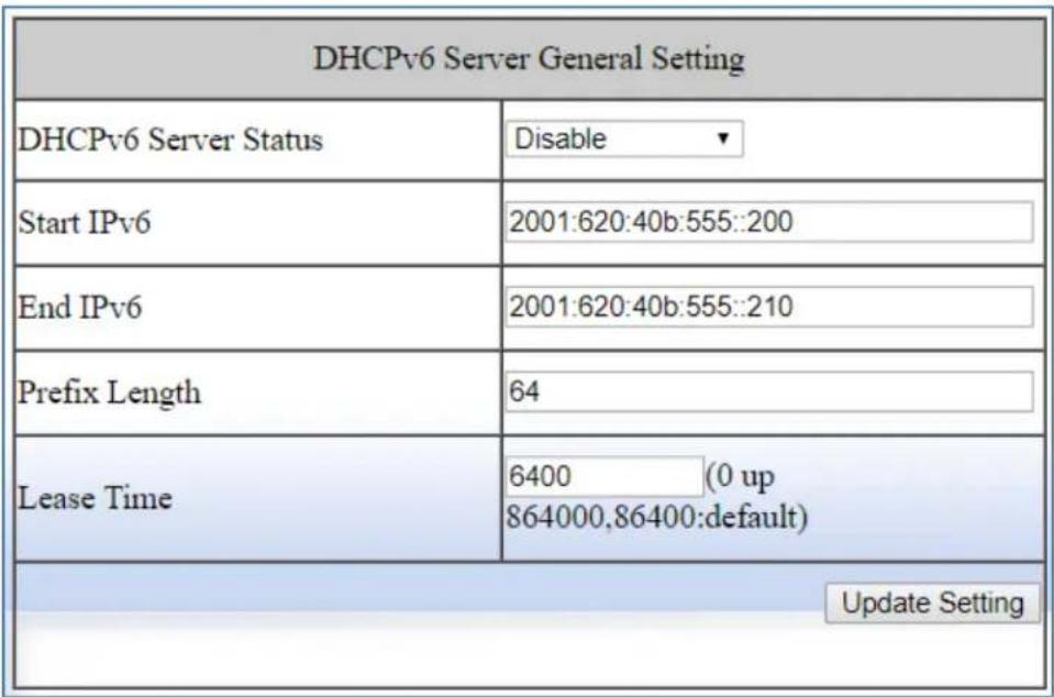
Figure 157: DHCPv6 Server Settings
DHCP Configuration Examples Using CLI Commands
For more information on CLI command usage see CLI Command Usage.
To set the DHCP server parameters:
CLI Command Mode: Global Configuration Mode
CLI Command Syntax:
dhcp-server range <start IP> <end IP>
dhcp-server subnet-mask <subnet mask in doted decimal notation>
dhcp-server gateway <IP address>
dhcp-server dns 1 <IP address>
dhcp-server dns 2 <IP address>
dhcp-server lease-time <0-864000>
Usage Example:
switch_a> enable
switch_a#configure terminal
switch_a(config)#dhcp-server range 192.168.7.100 192.168.7.107
switch_a(config)#dhcp-server subnet-mask 255.255.255.0
switch_a(config)#dhcp-server gateway 192.168.7.1
switch_a(config)#dhcp-server dns 1 1.2.3.4
switch_a(config)#dhcp-server dns 2 5.6.7.8
switch_a(config)#dhcp-server lease-time 86400
switch_a(config)#q
switch_a#
To enable the DHCP server and set the DHCP VLAN:
CLI Command Mode: Interface Configuration Mode
CLI Command Syntax: dhcp-server enable; no dhcp-server enable
Usage Example:
switch_a> enable
switch_a#configure terminal
switch_a(config)#interface vlan1.100
switch_a(config-if)#dhcp-server enable
switch_a(config-if)#no dhcp-server enable
switch_a(config-if)#q
switch_a(config)#q
switch_a#
To check what IP addresses has been allocated:
CLI Command Mode: Privileged Exec Mode
CLI Command Syntax: show dhcp-server binding
Usage Example:
switch_a> enable
switch_a#show dhcp-server binding
Mac Address IP-Address Expires in
a4:ba:db:de:d6:2f 192.168.7.100 23 hours, 57 minutes, 15 seconds
switch_a#
DHCP Relay
General Overview
The DHCP relay function on an EtherWAN Switch forwards DHCP packets between clients and servers. This function is used to forward requests and replies between clients and servers when they are not on the same physical subnet.
Configuring the DHCP Relay
To navigate to the DHCP Relay page:
- Click on the + next to Other Protocols
- Click on DHCP Relay
You can use the GUI to set the following DHCP server parameters:
• DHCP relay Enable/Disable
- DHCP Remote ID Type – This tells the switch which parameter to use when communicating with the DHCP Server
- Options are IP-ADDRESS or MAC-ADDRESS
- Remote ID VALUE – This shows the current value of the IP-ADDRESS or MAC-ADDRESS in Hexadecimal format.
To set the DHCP Relay parameters:
- Set the DHCP Relay Status to Enable or Disable
- Set the Remote ID TYPE to IP-ADDRESS or MAC-ADDRESS
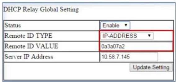
- Set the Server IP Address to the IP address of your DHCP Server
- Click on Update Setting
To set the DHCP Relay agent per port:
- Select Enable or Disable under the Status column next to the port that you need to change.
| Port | Status | Circuit-ID | ||
| fe1 | Enable ▼ | 000101 | ||
| fe2 | Disable ▼ | 000102 | ||
| fe3 | Disable ▼ | 000103 | ||
| fe4 | Disable ▼ | 000104 | ||
| fe5 | Disable ▼ | 000105 | ||
| fe6 | Disable ▼ | 000106 | ||
| fe7 | Disable ▼ | 000107 | ||
| fe8 | Disable ▼ | 000108 | ||
- Click on Update Setting
- Save the Configuration (see Save Configuration)
DHCP Relay Configuration Examples Using CLI Commands
For more information on CLI command usage see CLI Command Usage.
To Enable/Disable DHCP Relay:
CLI Command Mode: Global Configuration Mode
CLI Command Syntax:
dhcprelay enable
no dhcprelay enable
Usage Example:
switch_a> enable
switch_a#configure terminal
switch_a(config)#dhcprelay enable
switch_a(config)#write memory
switch_a(config)#q
switch_a#
To set the DHCP Relay Remote ID TYPE:
CLI Command Mode: Global Configuration Mode
CLI Command Syntax:
dhcprelay remote-id <ip-address/mac-address>
Usage Example 1:
switch_a> enable
switch_a#configure terminal
switch_a(config)#dhcprelay remote-id ip-address
switch_a(config)#write memory
switch_a(config)#q
switch_a#
Usage Example 2:
switch_a> enable
switch_a#configure terminal
switch_a(config)#dhcprelay remote-id mac-address
switch_a(config)#write memory
switch_a(config)#q
switch_a#
To set the DHCP Relay DHCP Server IP:
CLI Command Mode: Global Configuration Mode
CLI Command Syntax:
dhcprelay serverip <A.B.C.D>
A.B.C.D = The DHCP Server IP Address (ex:192.168.2.2)
Usage Example 1:
switch_a> enable
switch_a#configure terminal
switch_a(config)#dhcprelay serverip 192.168.2.2
switch_a(config)#write memory
switch_a(config)#q
switch_a#
Contact Information
EtherWAN System, Inc.
www.etherwan.com
USA Office
2301 E. Winston Road
Anaheim, CA 9280
Tel: +1-714-779-3800
Email: info@etherwan.com
Pacific Rim Office
8F., No.2, Alley 6, Lane 235, Baoqiao Rd.
Xindian District, New Taipei City 231
Taiwan
Tel: +886 -2- 6629-8986
EtherWAN has made a good faith effort to ensure the accuracy of the information in this document and disclaims the implied warranties of merchantability and fitness for a particular purpose, and makes no express warranties, except as may be stated in its written agreement with and for its customers.
EtherWAN shall not be held liable to anyone for any indirect, special or consequential damages due to omissions or errors. The information and specifications in this document are subject to change without notice.
Copyright 2023. All Rights Reserved.
All trademarks and registered trademarks are the property of their respective owners
July 14, 2023

- EtherWAN
- Hardened Managed Ethernet Switch Firmware 4.02
- All Rights Reserved
- Disclaimer of Liability
- Registered Trademarks
- Warranty
- Products Supported by this Manual:
- Contact EtherWAN Systems
- Table of Contents
- Preface....xiv
- Computer Setup.... 17
- Setting the initial IP address.... 19
- CLI Command Usage.... 20
- System Menu (web interface) 23
- Diagnostics 60
- Port 74
- Switching....90
- Trunking 123
- STP/Ring Page – Overview 133
- STP/Ring Page - Configuring RSTP 134
- STP/Ring Page - Configuring MSTP 145
- STP/Ring Page - Alpha Ring 162
- STP/Ring Page – Alpha Chain 173
- STP/Ring Page - Advanced Setting.... 179
- VLAN....184
- QoS 198
- ACL (Access Control List) 207
- SNMP 234
- AAA/802.1x (Authentication, authorization, and accounting).... 247
- LLDP 255
- Other Protocols.... 274
- PREFACE
- Audience
- Document Revision Level
- Applicable Models
- Release Notes for Firmware 4.02
- NEW FEATURES
- Changed
- Firmware 4.02.3.2
- Document Conventions
- Safety and Warnings
- Typographic Conventions
- COMPUTER SETUP
- Management Methods and Protocols
- Default IP
- Login Process and Default Credentials
- SETTING THE INITIAL IP ADDRESS
- Simple IP Addressing
- CLI COMMAND USAGE
- Navigating the CLI Hierarchy
- CLI Keyboard Shortcuts
- CLI Command modes
- Global Configuration Mode
- MSTP Configuration Mode
- Example:
- Interface Configuration Mode
- VLAN Database Configuration Mode
- Saving a Configuration from the CLI
- SYSTEM MENU (WEB INTERFACE)
- System Information
- - System Name
- - Firmware Version
- - System Time
- - MAC Address
- - Default Gateway
- - DNS Server
- - System Location
- - VLAN ID
- - Current User Information
- System Name/Password
- System Name/Password using the CLI
- System Name
- Password
- Show Switch Model using the CLI
- Configure the Reset Button
- Reset Button
- IP Address
- DHCP Client
- DHCPv6
- Default Gateway
- DNS Server
- IP Address - Configuration using the CLI
- Domain Name Server (DNS)
- Enable/Disable DHCP Client on a VLAN
- Enable/Disable Static IP on a VLAN
- Set the IPv6 Address of an Interface
- Set the IPv6 Address through DHCP
- Enable/Disable DHCP Server for IPv6
- Configure DHCPv6 server settings
- Management Interface
- HTTPS
- Telnet
- SSH (Secure Shell)
- Management Interface Configuration using the CLI
- Enabling/Disabling Telnet
- Enabling/Disabling SSH
- Enabling/Disabling HTTP and/or HTTPS
- Save Configuration Page
- Save Configuration
- Load Configuration
- Backup Configuration
- Restore Default
- Auto Save
- Saving and Loading Configurations Using EB-232
- Enable / Disable Automatic Restore
- Save switch configuration to EB-232
- Load switch configuration from EB-232
- Save configuration from TFTP server to EB-232
- Delete configuration data on EB-232
- Compare configuration data on EB-232 to switch
- EB-232 Firmware upgrade
- Show firmware version on EB-232
- Configure Reset Button
- Show Running Configuration using the CLI
- Save Configuration Page using the CLI
- Load Configuration from a TFTP Server
- Save Configuration to a TFTP Server
- Auto Save Configuration
- Firmware Upgrade
- Firmware Update using the CLI
- Reboot
- Reboot using the CLI
- Logout
- Logout from the CLI
- User Account Page
- Changing the User Mode
- Creating a New User
- Changing an Existing User Account
- User Privilege Configuration
- User Account Settings using the CLI
- Multi-User Mode
- Single User Mode
- Radius User Mode
- Tacacs User Mode
- Permissions
- DIAGNOSTICS
- Utilization
- System Log
- Examples:
- System log using CLI commands
- show system-log
- Remote Logging
- Click on the Delete Syslog Server button
- Remote Logging using CLI commands
- Enable/Disable Remote Logging
- Add/Delete a Remote Logging Host
- ARP Table
- ARP Table using CLI Commands
- Route Table
- Route Table Using CLI Commands
- Usage Example:
- Alarm Setting
- Alarm Setting Using CLI Commands
- Set Normal State for Alarm Relay
- Configuring Email Alarm Notifications
- Email Alarm Notifications Using CLI Commands
- PORT
- Configuration
- Port Status
- Rate Control
- RMON Statistics
- Per Port VLAN Activities
- Port Security
- Using Port Security with Multiple VLANs
- Port Configuration Examples Using CLI Commands
- Setting the Port Description
- Enable or Disable a Port
- Setting the Port Speed
- Setting Port Duplex
- Enable or Disable Port Flow Control
- Display Port Status
- Setting a Port's Rate Control
- Display a Port's RMON Statistics
- Display a Port's VLAN Activities
- Disable Port on Link Down
- Enable MAC port security
- Disable MAC port security
- Assign MAC Addresses for Port Security
- Delete MAC Address for Port
- Set Port Security to Sticky Mode
- Disable Sticky Mode
- Display Port Security MAC Addresses
- SWITCHING
- Bridging
- Aging Time
- Threshold Level
- Storm Control Type
- Loopback Detect
- Loopback Detection (Global)
- Loopback Detect Action
- Loopback Detect Recovery Time
- Polling Interval
- Loopback Detection (Per Port)
- Storm Detect
- Enable/Disable Storm Detection
- Static MAC Entry
- Adding a Static MAC Address to a Port
- Removing a Static MAC Address from a Port
- Adding a MAC to the Static-MAC-Entry Discard Table
- Removing a MAC address from the Static-MAC-Entry Discard Table
- Port Mirroring
- Link State Tracking
- Enable/Disable Link State Tracking
- Port Settings
- PoE (Power over Ethernet) - System and Port Settings
- PoE System Setting
- PoE Port Setting
- PoE Scheduling
- PoE Watchdog
- Switch Configuration Examples Using CLI Commands
- Setting the Aging Time Value
- Enabling Port Isolation
- Setting Storm Control
- Enabling Loopback Detect (Global)
- Setting the Loopback Detect Action
- Setting the Loopback Detect Recovery Time
- Setting the Loopback Detect Polling Interval
- Enabling Loopback Detect (Port)
- Configuring Storm-Detect
- Storm Detect Packet Type
- Adding a MAC Address for Static-MAC-Entry Forwarding
- Discard a Static MAC Entry
- Configuring Port Mirroring
- Enabling a Link State Tracking Group
- Assigning a Port to a Link State Tracking Group
- Setting PoE Power Budget
- PoE Port Settings
- Enable
- fixed-power-limit
- Power-classification
- no poe power-classification enable
- Power-down-alarm
- Power-priority
- Scheduling
- Schedule-time
- Schedule-time-hour
- Extend PoE to 250 Meters
- TRUNKING
- Overview
- Static Channel Trunking
- Link Aggregation Control Protocol
- Port Trunking
- Interface 1 (see Figure 47)
- Version 2 (see Figure 48)
- LACP Trunking
- Version 1 (see Figure 49)
- To set the LACP System Priority
- Version 2 (see Figure 50)
- Trunking Configuration Examples Using CLI Commands
- Adding an Interface to a Static Trunk
- Adding an Interface to a LACP Trunk
- Setting the LACP Port Priority
- Setting the LACP Timeout
- STP/RING PAGE – OVERVIEW
- Choosing the Spanning Tree Protocols
- Spanning Tree Protocol (STP)
- Rapid Spanning Tree protocol (RSTP)
- Multiple Spanning Tree Protocol (MSTP)
- STP/RING PAGE - CONFIGURING RSTP
- Global Configuration Page
- Enabling the RSTP Protocol
- Additional Global Configuration page settings
- The Root Bridge & Backup Root Bridge
- Setting the Root Bridge and Backup Root Bridge
- Setting the MAX Age, Forward Delay and Hello Timer
- The Network Diameter
- Relationship between Max Age, Forward Delay and Hello Time
- RSTP Port Setting Page
- Spanning Tree Port Roles
- Path Cost & Port Priority
- Point to Point Link
- Edge Port
- RSTP Configuration Examples Using CLI Commands
- Enabling the Spanning Tree Protocol
- Bridge Priority, Max Age, Forward Delay, and Hello Time
- Modifying the Port Priority and Path Cost
- Manually Setting a Port to be a Shared or Point to Point Link
- Enabling/Disabling a port to be an Edge Port
- STP/RING PAGE - CONFIGURING MSTP
- Enabling the MSTP Protocol
- The CIST Root Bridge & Backup CIST Root Bridge
- Setting Bridge Priority
- Configuring the CST Network Diameter
- MSTP Properties Page
- Configuring an MSTP Region
- Configuring the IST Network Diameter
- MSTP Instance Setting Page
- Setting an MSTP Instance
- Modifying MSTP parameters for load balancing
- MSTP Port Setting page
- Adjusting the blocking port in a MSTP network
- MSTI Instance Port Membership
- MSTP Configuration Examples Using CLI Commands
- Enabling Spanning Tree for MSTP
- IST MAX Hops
- MSTP Regional Configuration Name and the Revision Level
- Creating an MSTI Instance
- Setting MSTI Priority
- Modifying CIST Port Priority and Port Path Cost
- Adding a Port to an MSTI Instance
- STP/RING PAGE - ALPHA RING
- Alpha Ring Setting Page
- EtherWAN Alpha-Ring Technology
- Implementing a Simple Alpha-Ring
- Alpha-Ring V2
- Connecting two Alpha-Ring Networks together (Ring Coupling)
- Connecting Additional Rings (Redundancy Pairs)
- Configuring Alpha Ring using CLI commands
- Enable Alpha Ring and Alpha Ring V2 Protocols
- Set the Ring Ports
- Show Ring, Port and All States
- Define a Ring's Blocked Port
- Set Delay Time for Restoration of a Failed Port
- Enable Ring Coupling
- Set Ring Coupling Ports
- Enable Redundancy Pairs
- Configure Redundancy Pairs
- Show Ring Coupling, Port Coupling, and Redundancy Pair States
- STP/RING PAGE – ALPHA CHAIN
- The Alpha Chain Protocol
- General Overview
- Alpha Chain Settings
- Global Settings
- Configuring the Alpha Chain Ports
- Alpha Chain Pass-Through Ports
- Configuring Alpha Chain using CLI commands
- Storm Control
- Configuring Chain Ports
- Configuring Chain Pass-Through Ports
- STP/RING PAGE - ADVANCED SETTING
- Advanced Bridge Configuration
- Advanced Per Port Configuration
- Configuring Spanning Tree Advanced Settings using CLI commands
- Enabling BPDU Guard Globally
- Enabling BPDU Guard on a Port
- Enabling BPDU Guard Error Disable-timeout
- Enabling the Loop Guard Feature
- VLAN
- Port Based VLAN vs. Tagged Based VLAN
- Configuring VLANs in Port Based VLAN Mode
- Enabling Port Based VLAN
- Port Based VLAN Configuration Examples
- Port Based VLAN Configuration Examples using CLI Commands
- VLAN Configuration in 802.1Q Tag Based VLAN Mode
- Enabling 802.1Q Tagged Based VLAN
- Configuring 802.1Q VLAN Database
- 802.1Q Tag Based VLAN Configuration Examples Using CLI Commands
- Configuring a 802.1Q VLAN
- Configuring an IP Address for a Management VLAN
- Removing an IP Address from a Management VLAN
- Configuring an Access Port
- Configuring a Trunk Port
- Add an IP to the Management VLAN
- Configuring the Port Type and the PVID setting
- Configuring the VLAN Egress (outgoing) Member Ports
- QOS
- Web GUI Interface
- QoS Global Configuration using the CLI Interface
- Enabling/Disabling QoS
- Enable/Disable QoS Trust
- 802.1p Priority Page
- 802.1p Priority Submenu – CLI Interface
- DSCP Page – HTTP Interface
- DSCP Submenu – CLI Interface
- QoS Interface Commands – CLI Interface
- ACL (ACCESS CONTROL LIST)
- IP Access List:
- IP Access List (Extended):
- MAC Access List:
- Layer 4:
- Configuring ACL
- ACL Policy Map
- Mac Access List
- Layer 4
- Bandwidth Limiting
- Applying a Policy Map to a Port
- Modifying/Adding an Existing Policy Map
- Adding a New ACL Class to an Existing Policy Map
- Adding an Existing ACL Class to an Existing Policy Map
- Removing an ACL Class
- To remove an existing ACL Policy Map entirely, follow the instructions below:
- ACL Configuration Examples Using CLI Commands
- Enabling QoS
- Creating a Standard IP Access List
- Creating an Extended IP Access List
- Creating a MAC Access List
- Creating an ACL Class Map with Layer 4 Access List
- Creating a ACL Class Map with an IP or MAC Access List
- Creating an ACL Policy Map
- Appling an Existing ACL Policy to a Port
- Deleting an ACL Class
- Deleting an ACL Policy
- SNMP
- SNMP General Settings
- Configuring SNMP v1 & v2 Community Groups
- Configuring SNMP v3 Users
- Adding SNMP v3 Users to the switch
- Deleting SNMP v3 Users from the switch
- SNMP Configuration Examples Using CLI Commands
- Enabling SNMP and configuring general settings
- Configuring SNMP Traps
- Adding SNMP v3 Users
- AAA/802.1X (AUTHENTICATION, AUTHORIZATION, AND ACCOUNTING)
- Configuring Radius from the GUI
- Enabling Radius
- Adding a Radius Server
- Enabling 802.1X on a Port
- Configuring TACACS+ from the GUI
- Enabling TACACS+
- Adding a TACACS+ Server
- AAA/802.1x Configuration Using the CLI
- View RADIUS Status
- Enable RADIUS Globally
- Configure MAC-Based Authentication
- TACACS+ Authentication and Authorization
- Configure TACACS+ Server
- LLDP
- LLDP General Settings
- Enable/Disable LLDP
- Holdtime Multiplier
- Global TLV Setting
- LLDP Ports Settings
- Enabling LLDP transmission for a specific Port
- Enabling LLDP Reception for a specific Port
- Enabling Notifications
- LLDP Neighbors
- LLDP Statistics
- LLDP MED Network Policy
- LLDP MED Location ID
- LLDP MED Port Settings
- LLDP Configuration Examples Using CLI Commands
- LLDP Holdtime Multiplier
- LLDP Transmit Interval
- Enable/Disable Global LLDP TLVs
- Enabling LLDP Transmit on a Port
- Enabling LLDP Receive on a Port
- Enabling LLDP Notify
- Enabling Transmission of the Management IP
- Enabling Specific TLV's on a Port
- Enabling LLDP MED TLV's on a Port
- Set LLDP-MED location information
- OTHER PROTOCOLS
- GVRP
- Enabling the GVRP Protocol at the Global Level
- Enabling the GVRP Protocol at the Port Level
- GVRP Configuration Examples Using CLI Commands
- IGMP Snooping
- - Disabled:
- - Passive mode:
- - Querier mode:
- Enabling the IGMP Snooping Modes
- Configuring IGMP Snooping General properties
- Configuring IGMP Passive Mode Specific properties
- Configuring IGMP Querier Mode Specific properties
- Configuring IGMP Unknown Multicast Forwarding
- Disabled Mode Forwarding Port Configuration
- Passive Mode Forwarding Port Configuration
- No IGMP Querier port present
- IGMP Querier port present or no IGMP Querier port present
- IGMP Querier Mode Forwarding Port Configuration
- Monitoring Registered Multicast Groups
- IGMP Configuration Examples Using CLI Commands
- Network Time Protocol (NTP)
- Setting RTC Time
- Enabling NTP
- Setting the NTP Server IP Address
- Setting the Time Zone
- Setting the Polling Period
- Manually Syncing Time
- Daylight Savings Time - Weekday Mode
- Daylight Savings Time – Date Mode
- Network Time Protocol Configuration Examples Using CLI Commands
- GMRP
- GMRP Normal mode
- GMRP Fixed mode
- GMRP Forbidden mode
- GMRP Forward All mode
- GMRP Disabled mode
- Enabling the GMRP Feature Globally on the Switch
- Configuring the GMRP Feature Per Port
- GMRP Configuration Examples Using CLI Commands
- DHCP Server
- Configuring the DHCP Server
- Click on the Update Setting button.
- DHCP Configuration Examples Using CLI Commands
- DHCP Relay
- Configuring the DHCP Relay
- DHCP Relay Configuration Examples Using CLI Commands
- no dhcprelay enable
- Contact Information
- EtherWAN System, Inc.
- www.etherwan.com
- USA Office
- Pacific Rim Office
Brand : EtherWAN
Model : EX78934E-0VB
Category : Network Card/Adapter