
Cavalier SHDR-1560760-08 - Shower system DreamLine - Free user manual and instructions
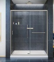
Find the device manual for free Cavalier SHDR-1560760-08 DreamLine in PDF.


| Product Type | Sliding Shower Door System |
| Brand | DreamLine |
| Model | Cavalier SHDR-1560760-08 |
| Number of Door Panels | 2 |
| Glass Coating | ClearMax™ anti-spot and anti-soap buildup coating |
| Glass Surface Orientation | ClearMax label must face inside of shower |
| Hardware Material | Stainless steel (profiles, rails, towel bars) |
| Included Components | 2 door glass, 2 wall profiles, top & bottom guide rails, 2 towel bars, 4 roller assemblies, wall bumpers, guide block, hardware |
| Adjustability | Adjustable roller assemblies for door tilt and leveling |
| Installation Requirements | Two people required; professional installation recommended |
| Minimum Threshold Flat Space | 2-3/4 inches |
| Wall Out-of-Plumb Tolerance | Up to 3/8 inch per wall profile |
| Silicone Cure Time | 24 hours before use |
| Glass Care | Wipe with soft cloth or squeegee after each use; non-abrasive cleaners only |
| Hardware Care | Wipe with soft cloth; avoid ammonia, bleach, acid; clean stainless steel weekly |
| Acrylic Back Wall Care | Non-abrasive spray or cream cleaners; avoid aerosol sprays |
| Safety Warning | Do not lift glass by towel bars; use assistant or suction cup for heavy glass |
| Compliance | Consult local building codes |
| Warranty | Contact DreamLine for details |
| Customer Support | 1-855-831-2126 (M-F 8AM-7PM EST, Sat 9AM-5PM EST) or Support@DreamLine.com |
Frequently Asked Questions - Cavalier SHDR-1560760-08 DreamLine
User questions about Cavalier SHDR-1560760-08 DreamLine
0 question about this device. Answer the ones you know or ask your own.
Ask a new question about this device
Download the instructions for your Shower system in PDF format for free! Find your manual Cavalier SHDR-1560760-08 - DreamLine and take your electronic device back in hand. On this page are published all the documents necessary for the use of your device. Cavalier SHDR-1560760-08 by DreamLine.
USER MANUAL Cavalier SHDR-1560760-08 DreamLine
Shower Door Installation Instructions
IMPORTANT
DreamLine® reserves the right to alter, modify or redesign products at any time without prior notice. For the latest up-to-date technical drawings, manuals or any other details please refer to your model's web page on DreamLine.com
MODEL #s
SHDR-1560760-08
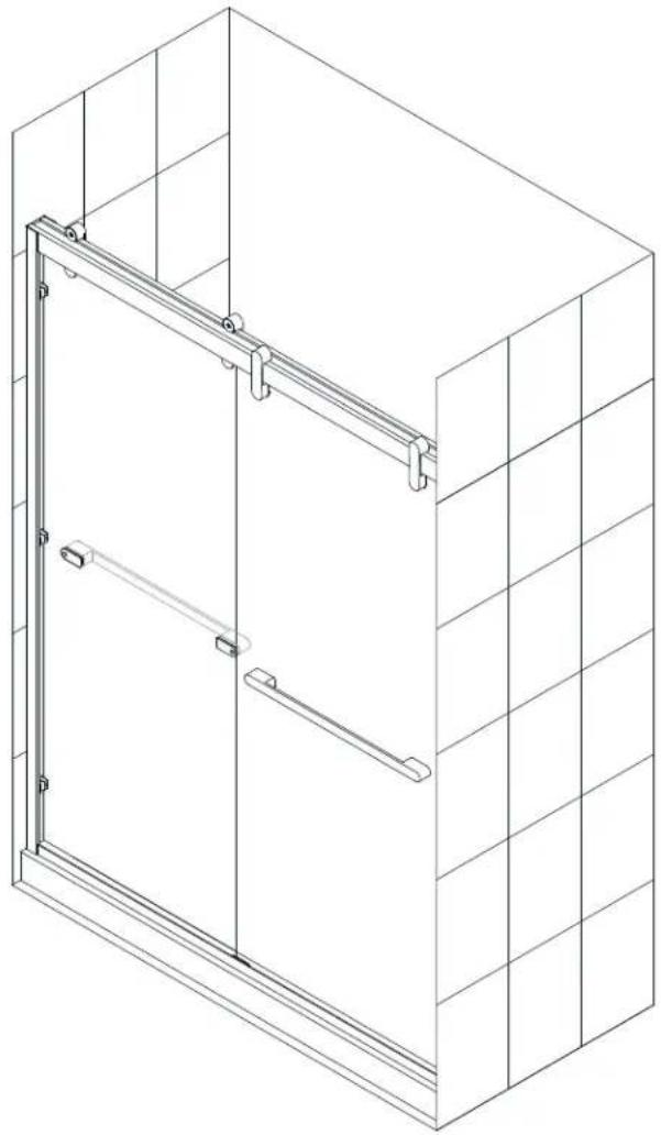

Questions?
Please Call DreamLine Customer Support: 1-855-831-2126
Hours of Operation M-F 8AM - 7PM EST and Saturday 9AM - 5PM EST
Support@DreamLine.com

This model is treated with DreamLine's exclusive ClearMaxTM Glass technology. This is a specially formulated coating that prevents the build up of soap and water spots.
Install the surface with the ClearMax™ label towards the inside of the shower. Please note that depending on the model, the glass may be coated on either one or both surfaces.
For best results, squeegee the glass after each use and dry with a soft cloth.
Preparation
-
Prior to installation, examine all boxes and packages for shipping damage and compare the piece count with your packing slip. After opening all boxes and packages read this introduction carefully. Check that all of the needed parts are included in the package by checking off the components on the "Detailed Diagram of Shower Door Components". If the unit has been damaged, has a finishing defect, or has missing parts, please contact our customer support department within 3 business days of the delivery date. Please note that DreamLine® will not replace any damaged products or missing parts free of charge after 3 business days or if the product has been installed. Feel free to contact DreamLine® if you have any questions, and please provide an order number, job name or other proof of purchase to help us identify your original order.
-
Please note that you should consult your local building codes with questions on installation compliance standards. Building and plumbing codes may vary by location, and DreamLine® is not responsible for code compliance standards for your project and will not accept any returns.
-
If this unit is going to be installed in a new construction, please install all of the required plumbing and drainage before installing the shower. Use a competent and licensed (if required by local code) plumber for all plumbing installation.
-
Please make sure that prior to beginning the installation, the surfaces are leveled and solid and will be able to support the total weight of the unit. Also make sure the walls are at right angles. Irregular installation surface level, radius corners or improper angle of side walls will result in serious problems for your installation. Please, note that some adjustments and drilling might be necessary during the installation process.
-
Please protect all primary surfaces of the product during installation. Never set your glass down directly onto a tile floor. Leave corner protectors in place until necessary to remove them. Always use a piece of wood or cardboard to protect the bottom edge and corners of the glass prior to and during installation.
-
This unit must be installed upon a finished threshold and against finished walls.
-
This model can accommodate up to 3/8" per wall profile for out-of-plumb conditions. Verify that your walls are plumb before proceeding with the installation.
-
This model requires a minimum 2-3/4" of flat threshold space for installation.
-
This model requires two people for installation.
-
Professional installation recommended.

NOTE:
DO NOT install the towel bars onto the glass until instructed. DO NOT lift the glass using the towel bars.
This could result in damage to the glass and /or serious personal injury.
Always use an assistant or a professional grade glass suction cup when handling heavy glass.
Tools

Level

Tape Measure

Pencil

Phillips
Screwdriver
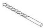
Drill bit
(∅=5/16")

Caulk

Power Drill
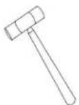
Hammer

Chop saw (with blade for cutting Stainless Steel)

Metal File
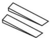
1/4" shims
wood or plastic
NOTE: Unpack your unit carefully and inspect it. Lay it out and identify all parts using the detailed diagram and packing list in this manual as a reference. Before discarding the carton, check for small hardware bags that may have fallen to the bottom of the box. If any parts are damaged or missing, please contact DreamLine® for replacement. The shipping boxes may contain extra parts not used in your model configuration.
NOTE: Retain these installation instructions for future reference.
Detailed Diagram of shower door components


LEARMAX™
The glass surface with the ClearMax™ label must be installed to face inside of the shower
| Parts List | |||||
| # ITEM Qty # ITEM Qty | |||||
| 1 | Wall Profile (1 Left / 1 Right) 2pcs | 7 | Towel Bar 2pcs | ||
| 2 | Door Glass 2pcs | 8 | Roller assembly 4pcs | ||
| 3 | Top Guide Rail 1pc | 9 | ∅8 Plastic Wall Anchor 6pcs | ||
| 4 | Bottom Guide Rail | 1pc | 10 | ST4.2×40 Truss Head screw | 6pcs |
| 5 | Wall Profile Bumper (with cap) | 6pcs | 11 | M4 x 10 Round Head screws | 8pcs |
| 6 | Guide Block (with caps) | 1pc | 12 | Allen Wrench 3mm/4mm | 1 each |
| Boxes | |||||
| # | Box | Box Contents by Part # | |||
| 1 | Glass Box (GL) | 2 | |||
| 2 | Accessory Box (AC) | 1. 3. 4. 5. 6. 7. 8. 9. 10. 11. 12 | |||
| 3 | Spare Acc parts bag | 9. 10. 11 | 2 each | ||
Installation steps
- Measure the finished opening at the bottom and at the model height (76" for shower). Use these dimensions as "W" in step #2. Also check the threshold for level and the walls for plumb.
See Fig 1 for details

Fig 1
- Cut the Top Guide Rail (#03) and Bottom Guide Rail (#04) using a chop saw.
The Top Guide Rail (#03) can be cut from either end.
Cut the Upper Guide Rail (#03) -5/16" shorter than the top dimension W.
W - 5/16" = finished cut length "L"
The Bottom Guide Rail (#04) needs to be cut equally from both ends to keep the center guide holes centered.
Cut the Bottom Guide Rail (#04) -3/8" shorter than the bottom dimension W.
W - (3/8" divided by 2) = finished cut length "L" (or W - (3/16" x 2) = finished cut length "L").
S e
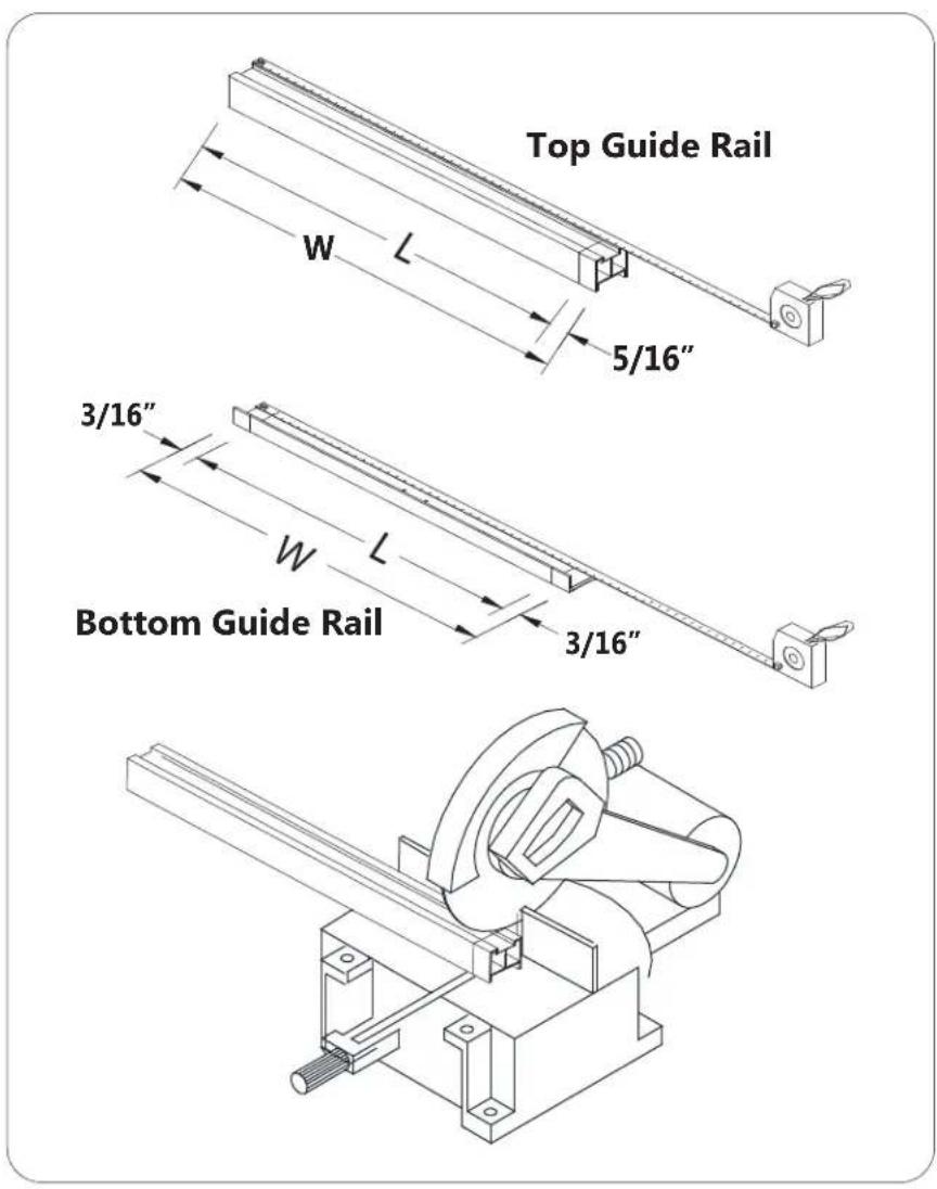
Fig 2
- Using a tape measure, position the Bottom guide rail (#04) parallel to front edge of the threshold and mark its position. Use the wall profiles to help center the Bottom guide rail (#04) on the width to allow proper spacing for installation.
See Fig 3 for details
NOTE: There is one left and one right Wall profile (#01). The bottom of the wall profile has a cut-out that will fit over the Bottom guide rail (#04).
See Fig 4 for details
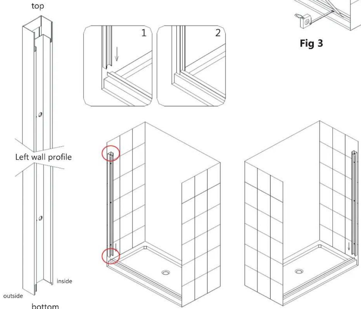

Fig 4
- Use a level to make the Wall profiles (#01) plumb and mark the position on the wall. Mark the large holes for drilling.

Fig 5

- Remove the Wall profiles (#01) and drill ∅5/16" holes. Insert the Wall Anchors (#09).
See Fig 6 for details
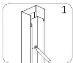


Fig 6
- Apply silicone to the bottom of the Bottom guide rail (#04) and place it back in position on the threshold along the mark you made in step #3. Use the wall profiles to help center the Bottom guide rail (#04) on the width to allow proper spacing for installation.
See Fig 7 for details

- Apply silicone to the back of each Wall profile (#01), position them on the walls along your marks and attach using the ST4.2 x 40 Truss Head screws (#10).
S e e F i g

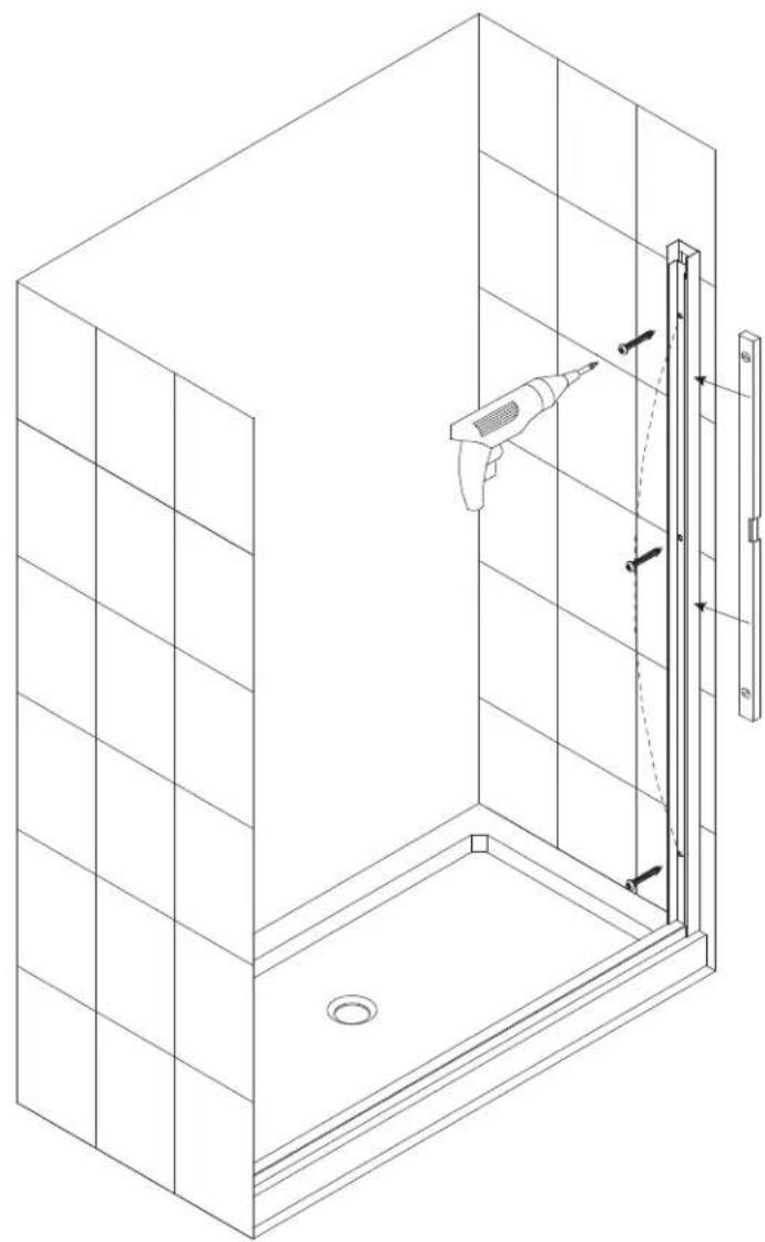
Fig 8
- Install Wall profile bumpers (#05) using the M4 x 10 Round Head screws (#11) into the pre-drilled holes on the wall profiles.
See Fig 9 for details
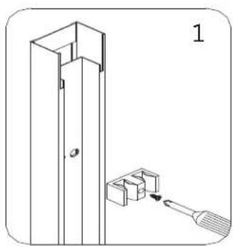


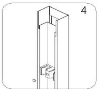
Fig 9
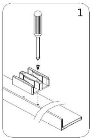
- Install the Guide Block (#06) to the Bottom Guide rail (#04) using two of the M4 x 10 Round Head screws (#11). Cover the holes with the decorative caps.
See Fig 10 for details


- Install the Top Guide Rail (#03) into the notches in Wall profiles (#01).
See Fig 11 for details


NOTE:
DO NOT install the towel bars onto the glass until instructed.
DO NOT lift the glass using the towel bars.
This could result in damage to the glass and /or serious personal injury.
Always use an assistant or a professional grade glass suction cup when handling heavy glass.
Note: Bring one lite of Door glass (#02) into the shower area. (Use padding to protect the glass and shower surfaces). Install the outer door glass first and then install the inner door glass, (otherwise you may have difficulty getting the inner door glass into the shower after the outer door glass is installed).
- From inside of the shower, carefully place the outside door glass down into the Guide Block (#06), and then move the door glass into an upright position beneath the Top Guide Rail (#03) (be careful not to make contact with the upper guide rail).
Next, lift the door glass just enough to insert a 1/4" shim under each corner to hold the door glass in a postion that will allow you to attach the Roller Assemblies (#08).
Place two roller assemblies onto the Top Guide Rail (#03) and attach the door glass as shown. (Fig 12.2 & 12.3) Rotate the bushings to a neutral position and then tighten the allen bolt.
Attach the decorative cover (Fig 12.3). Once the door glass is securely attached to the roller assemblies, remove the shims.
S e e
TIP: Use an assistant and a pair of 1/4" shims beneath the door glass to make it easier to install and adjust the door glass.


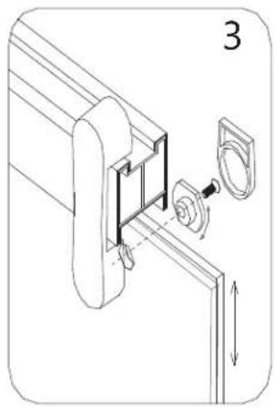
Fig 12
- Next, install the inner door glass in the same manner: placing it into the Guide Block (#06) raising the glass beneath the Top Guide Rail (#03), and inserting the 1/4" shims under both corners of the glass. Attach the Roller Assembly (#08) that is accessible. Move the outer door glass to the side to provide access to install the remaining Roller Assembly (#08) onto the inner door glass.


Fig 13
- Rotate the adjustment bushing to adjust the tilt of the door glass to get a better seal as necessary. Firmly tighten the bolt and snap the cover plate over the bushing.
See Fig 14 for Details

Fig 14
- After the door glass is installed onto the roller assemblies, install the Towel bars (#07) onto the door glass as shown. Make sure to use all rubber gaskets and sleeves to protect the glass. The door glass will need to be moved aside to access both ends of the towel bars during the process.
See Fig 15 for Details

Fig 15
- Apply good quality mildew-resistant silicone to the interior of the shower door along the walls and threshold.
Allow 24 hours for the silicone to fully cure before using the shower.
See Fig 16 for details

Product Maintenance
BASES and BACKWALLS: To ensure long lasting life for your acrylic back walls: wipe them off after each use with a soft cloth. To clean the acrylic back walls use non-abrasive sprays or cream based cleaners. Avoid the use of aerosol spray cleaners. Never use abrasive cleansers, metal brushes or scrapers that could scratch or dull the surface.
GLASS: To ensure long lasting life for your glass shower products: wipe them off after each use with a soft cloth. Rinse and wipe off the glass using either a soft cloth or a squeegee to prevent soap buildup and water spots (Hard water can etch the surface of the glass over time if left to dry). To prevent scratching the surface: never use abrasive cleaners or cleaning products that contain scouring agents. Never use bristle brushes or abrasive sponges that may scratch the surface.
HARDWARE: To ensure a long lasting finish: wipe off the metal parts after each use with a soft cloth. Do not use abrasive cleaners or cleaning products containing ammonia, bleach or acid. If accidentally used, rinse the surface as soon as possible to prevent damage to the finish (peeling or corrosion). After cleaning the polished finishes, rinse thoroughly and wipe dry with soft cloth. Clean stainless steel surfaces at least once a week. When applying stainless steel cleaner or polish to stainless steel hardware, work with (not across) the grain. Never use an abrasive sponge or cloth, steel wool or wired brush as these may permanently scratch the surfaces.
NOTE: To maximize the life of your door, it is important to regularly inspect the glass and other hardware for misalignment, proper attachment, and/or damage. Contact DreamLine with any questions or concerns.
DREAMLINE®
For more information on DreamLine® Shower Doors and Enclosures please visit DreamLine.com


Brand : DreamLine
Model : Cavalier SHDR-1560760-08
Category : Shower system