
VLo Ultra-12 - Heating Warmup - Free user manual and instructions
Find the device manual for free VLo Ultra-12 Warmup in PDF.


| Type of product | Electric underfloor heating mat |
| Brand | Warmup |
| Model | VLo Ultra-12 |
| Dimensions (width x length) | 0.5 m x 12 m (approximate coverage 12 m²) |
| Weight | ~2 kg |
| Power rating | 1800 W (150 W/m²) |
| Voltage | 240 V AC, 50/60 Hz |
| Current draw | 7.5 A |
| Heating cable type | Single conductor, cold tail length 3 m |
| Floor coverings compatible | Tile, stone, vinyl, laminate, engineered wood |
| Thermostat compatibility | Warmup thermostats (e.g., 4iE, 6iE, UFH) |
| Programmable functions | Yes, with compatible thermostat (7-day scheduling, open window detection) |
| Overheat protection | Yes, built-in NTC sensor |
| IP rating | IP67 (splashproof, suitable for wet rooms) |
| Thickness | 3 mm (low profile, minimal floor build-up) |
| Maintenance | No maintenance required; do not cut or modify heating mat |
| Cleaning | Clean floor covering as per manufacturer's instructions |
| Safety certifications | CE, EMC, LVD, RoHS |
| Warranty | 10 years (limited, upon registration) |
| Installation | Embedded in self-leveling compound or thinset mortar |
| Repairability | Heating cable can be repaired with repair kit; do not splice |
| Spare parts | Cold tail extension kit, repair kit, thermostat |
Frequently Asked Questions - VLo Ultra-12 Warmup
User questions about VLo Ultra-12 Warmup
0 question about this device. Answer the ones you know or ask your own.
Ask a new question about this device
Download the instructions for your Heating in PDF format for free! Find your manual VLo Ultra-12 - Warmup and take your electronic device back in hand. On this page are published all the documents necessary for the use of your device. VLo Ultra-12 by Warmup.
USER MANUAL VLo Ultra-12 Warmup
VLo Ultra-12
Low Build System
Installation manual

SAFETY Net Installation-Guarantee

Warmup®
The world's best-selling floor heating brand™
Over 2.5 million installations in more than 72 countries
Experience MyHeating™
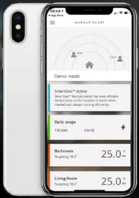

SmartGeo™
Unique SmartGeo™ automatically turns down the heating when you're out.

Easy to use
Simple and secure setup using WiFi, with 24/7 technical support.

AutoSwitch™
Always on the best tariff, automatically. Reduce energy bills by over £400
Download now for iOS and Android

Available on the App Store


GET IT ON Google Play

GE DBWE Thermostat

www.warmup.co.uk
Installation summary 4
Components available from Warmup....6
Important installation information....7
Step 1 - Selecting the installation method....8
Tiled floors....8
All floor finishes - bonded....9
Floating floor finishes....10
All floor finishes - floating....11
Step 2 - Subfloor considerations....12
Step 3 - Installing VLo Ultra-12....13
Step 4 - Lay the pipe....15
Step 5A - Laying a tile floor covering .... 19
Step 5B - All floor finishes - bonded ....20
Step 5C - Laying floating floor finishes....21
Step 5D - All floor finishes - Dry 22
Testing information 23
Troubleshooting....24
Technical specifications 25
Warranty 26
Acoustic Performance 28
System Performance 29
Your Warmup ^® underfloor heating system has been designed so that installation is quick and straight forward, but it is important that the instructions in this manual are followed to ensure that your underfloor heating system performs correctly. Please ensure that you have the components and working drawings necessary for this system before you begin installation.
Warmup plc accepts no liability, expressed or implied, for any loss or consequential damage suffered as a result of installations which in any way contravene the instructions that follow.
It is important that before, during and after installation that all requirements are met and understood. If the instructions are followed, you should have no problems. If you require help at any stage, please contact our helpline.
You may also find a copy of this manual, wiring instructions and other helpful information on our website
www.warmup.co.uk
Please also read the full instructions that follow this section.
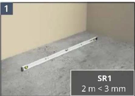
- Ensure the subfloor is clean, dry and prepared to an SR1 standard. See subfloor considerations page for more information.

natural_image
Close-up of a white plastic component with a black curved object on a gray surface (no text or symbols visible)- For bonded constructions in dry areas a high temperature acrylic adhesive can be used to bond the Ultra-12 panels to the subfloor.
Press the boards down firmly into the adhesive to create the necessary adhesion.

natural_image
3D rendered object on a textured surface, possibly a mechanical part or tool, with no visible text or symbols.- For bonded constructions in wet or dry areas and compatible S1 or S2 flexible tile adhesive is recommended.
Press the boards down firmly into the adhesive to create the necessary adhesion.

natural_image
Exterior view of a modern office building (no signage)- Starting from the manifold location fit the service panels following the pipe layout shown on the working drawings.
- For bends use the curve service panels, snapping or cutting the straight service panels at 45° and butting them tightly together.

natural_image
Interior view of a modern building with patterned flooring and ceiling-mounted fixtures (no visible text or symbols)- Fit the curve panels at the end of the room referring to the working drawings.
- In fill the heated area with the straight panels.
- The plain panels can then be used in areas where underfloor heating will not be installed, i.e. under kitchen units.
natural_image
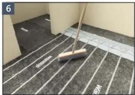
Floor with carpet and floor tiles, a broom, and a wall-mounted tool (no visible text or symbols)- Before installing the pipework in the panels it is advised to sweep or vacuum the floor area to clear any debris.
natural_image
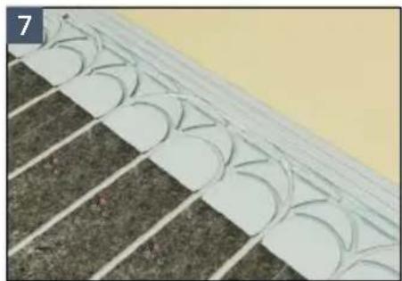
Close-up of a tiled roof corner with curved white panels and dark wood strips (no text or symbols visible)- Install the pipe in line with the projects working drawings, pressing it into the grooves of the Ultra-12 panels. Ensure the pipe is securely fixed into the grooves. - Route a 6 mm channel into the Ultra-12 panel for the floor sensor to be recessed into and install at least 300 mm into the heated area it will be controlling.
natural_image
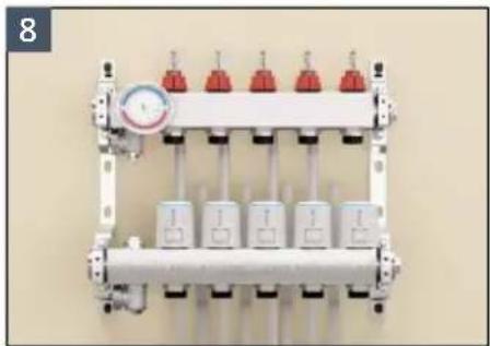
Electrical circuit board with pressure gauge and multiple cylindrical components (no visible text or symbols)• Measure and cut the pipe so that it reaches both the flow and return ports on the manifold.
natural_image
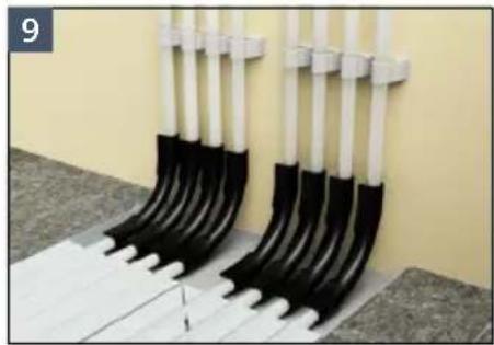
Close-up of black and white plastic pushers mounted on a white sheet, against a plain yellow wall (no text or symbols visible)- Use Warmup pipe bend supports to hold the flow and return pipe at a 90° angle as it exits the floor towards the manifold.
• Refer to the manifold manual for detailed information on mounting, pressure testing and commissioning.
natural_image
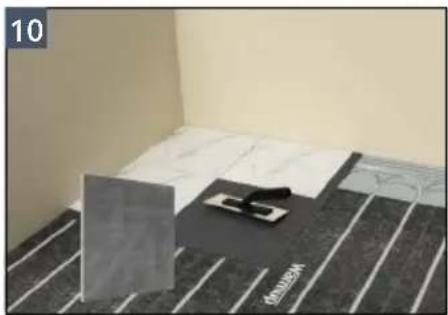
Interior view of a minimalist room with patterned floor and wall-mounted objects (no visible text or symbols)- Lay your chosen floor covering in accordance with floor manufacturers instructions.

• Install your Warmup thermostat referring to their installation instructions. The system must be connected to and controlled with a thermostat and sensor.
Product Code Description

natural_image
Close-up of a rectangular metal sheet with white horizontal lines, no text or symbols visibleA VLo Ultra-12 Low Build Straight Panel
ULTRA12-SP-PANEL

natural_image
3D-printed metallic tile with repeating geometric patterns (no text or symbols)B VLo Ultra-12 Low Build Curve Panel
ULTRA12-CP-PANEL

natural_image
Metal corrugated metal sheet with parallel grooves (no text or symbols)© VLo Ultra-12 Low Build Straight Service Panel
ULTRA12-SS-PANEL

natural_image
Abstract 3D pattern with wavy gray and black lines on a light gray background, no text or symbols present.D VLo Ultra-12 Low Build Curve Service Panel
ULTRA12-CS-PANEL

natural_image
Rectangular concrete slab with visible texture and no text or symbolsE VLo Ultra-12 Low Build Plain Panel
ULTRA12-PP-PANEL
PERT-12xXX XX = lengths, 50, 60, 70m
Warmup PE-RT pipe 12 mm
Additional components that may be required as part of your Warmup heating installation:
| Manifold, mixing unit, actuators, valves and euroconus connectors |
| Wiring centre |
| Warmup thermostats |
| HiDECK Overlay 18 |
| HiDeck PRO Adhesive |
| Warmup perimeter strip |
| Mapei Ultraplan Renovation Screed 3240 |
| Adhesives |
Important installation information
On delivery of the Ultra-12 panels ensure that they are stored in a dry weather tight area, away from chemicals and that they are stacked horizontally on a flat and level surface.
Perform a site inspection. You will need to confirm that all measurements and other requirements on site match your working drawings. Ensure that all areas are correctly prepared, dry and protected from weather.
i Ensure the subfloor is prepared to an SR1 standard. Failure to do so may result in an unstable and noisy finished floor.
i Inspect the site for possible hazards that could damage the Warmup pipe, such as nails, staples, materials or tools.
Use a pipe cutter designed for plastic pipe ensuring that there are no burrs on the pipe ends. It is important to achieve a clean cut.
Do not pull pipe from the coil while it is sitting flat. It must be unwound from the coil, rotating the coil as the pipe is pulled from the inside.
Do not force the pipe into bends. It is easier to lay the pipe with a large radius and then gently pull the pipe to the required bend. The minimum bending radius is 5 times the diameter of the pipe.
Do not kink the pipe. Excessive bending of the pipe can cause it to kink, where this occurs flow may be obstructed or reduced. Kinked pipe must be repaired or replaced. To repair a kink, straighten the pipe and simply heat the area with a hot air gun until the kink disappears.
If installing levelling compound over Ultra-12, ensure it is suitable for use with compressible underfloor heating panels and applied as a single layer.
Before installing the floor finish, its suitability for use with underfloor heating and its maximum operating temperature should be checked against required operating conditions.
i Underfloor heating performs the most efficiently with conductive, low resistance floor finishes such as stone and tiles. Consideration should be given to the thermal resistance and temperature limits of the chosen floor covering and its impact on the system heat output.
| Tiled floors | |
| 1 | Tile Floor Finish |
| 2 | Flexible tile adhesive Tile adhesive used must be compatible with compressible panels such as Ultra-12, e.g. Warmup S2 flexible tile adhesive |
| 3 | Floor sensor Must be recessed into the Ultra-12 panel and taped in position. |
| 4 | Warmup 12 mm PE-RT pipe |
| 5 | Ultra-12 - Straight Panel |
| 6 | Ultra-12 - Curve Panel |
| 7 | Flexible tile adhesive e.g. Warmup S1/S2 flexible tile adhesive for wet or dry areas or compatible high temperature acrylic adhesive for dry areas |
| 8 | Warmup primer Refer to tile adhesive manufacturers instructions for priming requirements |
| 9 | Subfloor with a Surface Regularity of SR1 |
| All floor finishes - bonded | |
| 1 | Perimeter strip To allow for differential movement between finished floor level and walls |
| 2 | Floor finish |
| 3 | Minimum 12 mm single layer of compatible self-levelling compound e.g. Mapei Ultraplan Renovation Screed 3240 fibre reinforced levelling compound |
| 4 | Floor sensor Must be recessed into the Ultra-12 panel and taped in position. |
| 5 | Warmup 12 mm PE-RT pipe |
| 6 | Ultra-12 - Straight Panel |
| 7 | Ultra-12 - Curve Panel |
| 8 | Flexible tile adhesive e.g. Warmup S1/S2 flexible tile adhesive for wet or dry areas or compatible high temperature acrylic adhesive for dry areas |
| 9 | Warmup primer Refer to tile adhesive manufacturers instructions for priming requirements |
| 10 | Subfloor with a Surface Regularity of SR1 |
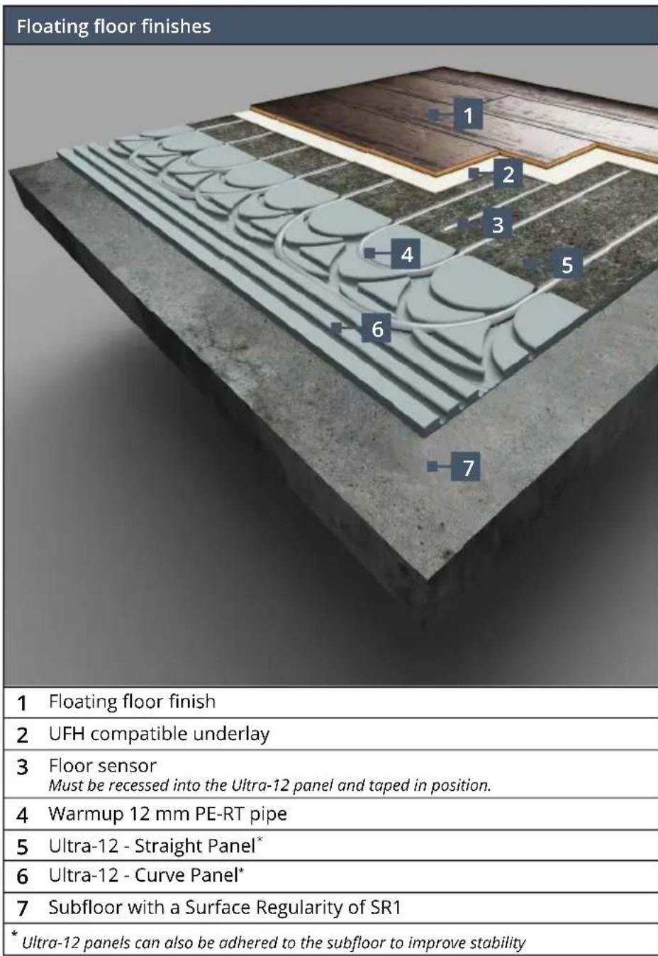
All floor finishes - floating

| 1 | Perimeter stripDCM-E-25 |
| 2 | Floor finish |
| 3 | Floating floor deckSuch as HiDECK 18 or 18mm P5 T&G chipboard. Install referring to their instructions |
| 4 | Floor sensorMust be recessed into the Ultra-12 panel and taped in position. |
| 5 | Warmup 12 mm PE-RT pipe |
| 6 | Ultra-12 - Straight Panel* |
| 7 | Ultra-12 - Curve Panel* |
| 8 | Subfloor with a Surface Regularity of SR1 |
| *Ultra-12 panels can also be adhered to the subfloor to improve stability | |
Ultra-12 may only be laid over structurally sound load bearing subfloors that are sufficient to support the additional load of the system, meet the requirements of the floor finish and the floors intended use.
Ensure the subfloor is dry and smooth, free of oil, grease and dust. If necessary an appropriate smoothing or levelling compound should be applied.
Where ceramic tiles are to be used over suspended floors ensure that the subfloor meets the Tile Associations minimum specifications.

Subfloors should be prepared to an SR1 standard.

For bonded floor finishes, Ultra-12 boards must be adhered to the subfloor.

If using temperature sensitive materials above Ultra-12, such as damp proofing or tanking systems, contact the manufacturer for advice.

Do not commence installation of the Ultra-12 panels without ensuring that the resulting floor construction will meet the requirements of the floors intended use and its finish.

- Ensure the subfloor is dry, clean, level to SR1 and free from dust or other substances that will prevent bonding.
- Prime the subfloor in line with the adhesive manufacturers instruction.

natural_image
Close-up of a metal tool resting on a textured surface, labeled '3A 3B' in the top-left corner (no other text or symbols visible)- For bonded constructions in dry areas a high temperature acrylic adhesive can be used to bond the Ultra-12 panels to the subfloor.
Apply the adhesive following its instructions.
For high temperature acrylic adhesives a 1-1.5 mm V-notch trowel is recommended.
Press the boards down firmly into the adhesive to create the necessary adhesion.

natural_image
Interior corner of a room with beige walls and gray floor tiles, no visible text or symbols- If you are planning to use a levelling compound over Ultra-12 install Warmup perimeter strip around the perimeter of the room and any permanent structures to allow for differential movement between finished floor and walls.

natural_image
Person sitting on a gray textured surface, possibly a vehicle or abstract object (no visible text or symbols)- For bonded constructions in wet or dry areas and compatible S1 or S2 flexible tile adhesive is recommended.
Apply the adhesive following its instructions.
For flexible tile adhesives a 6 mm square notched trowel is recommended.
Press the boards down firmly into the adhesive to create the necessary adhesion.

For irregular surfaces a larger trowel notch may be required.

- Starting from the manifold location fit the straight service panels, C, following the pipe layout shown on the working drawings. Use the plain panels, E where applicable.

natural_image
Exterior view of a wall-mounted heating element with ribbed insulation and a labeled point D (no text or symbols beyond label)- For bends use the curve service panels, D, snapping or cutting the straight service panels at 45° and butting them tightly together.

- Curve service panels, D, can be cut to be used to navigate around obstacles as shown.

- Fit the curve panels, B, at the end of the room referring to the working drawings. The plain panels, E, can then be used in areas where underfloor heating will not be installed, i.e. under kitchen units.
• In fill the heated area with the straight panels, A.

The boards can be cut using a utility knife. To prevent damage to the pipe, remove sharp edges and burrs from the edges aluminium pipe channels.
If the project has been supplied with a set of working drawings, follow the provided pipe layout. Ensure each circuits details are recorded in the commissioning log provided in the Warmup manifolds installation manual.
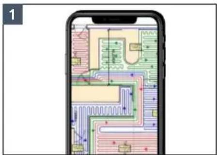
- Plan the circuit layout ensuring that the flow and return pipes can connect from the manifold to their respective heated area without crossing each other.

natural_image
Interior view of a room with tiled floor and carpet, featuring a broom and a pole (no visible text or symbols)- Before installing the pipework ensure the adhesive has cured where used. Sweep or vacuum the panels to clear any debris.
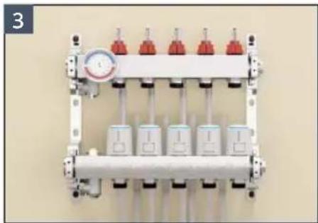
natural_image
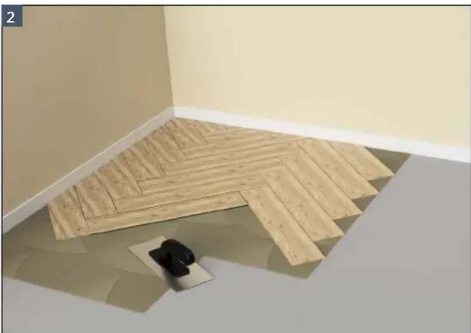
Industrial piping system with pressure gauge and multiple valves (no visible text or labels)- Ensure there is excess flow and return pipe at the manifold location which can be cut later after the pipe has been laid.

natural_image
Row of black and white electrical connectors mounted on a tiled floor against a yellow wall (no text or symbols visible)- Attach pipe bend supports to hold the pipe at a 90° angle as it enters the floor. Position the support so that the pipe rises straight to the manifold with approximately half the support within the floor.
- Leave a 150mm space the width of the manifold arms to allow for the curve pipe supports.

Feed pipes normally go through doorways but to minimise congestion, pipes can be fed through walls. Ensure holes drilled in the wall are below floor level and the pipe is protected with a conduit.

- Beginning from the manifold location, (i), following the projects working drawings, begin laying the pipe, pressing the pipe into the channels,
- Meander up and down the floor using both the large and small radius turns to create the first half of a double meander pattern. Once you reach the mid point of your circuit, double back and infill the remaining channels. The resulting double meander pattern, (ii), will ensure a more even floor temperature.
- Where required, route channels into the Ultra-12 panels as shown (iii).


natural_image
Close-up of a textured surface with parallel white panels and dark granular material, no visible text or symbols- Route a 6 mm channel into the Ultra-12 panel for the floor sensor to be recessed into.
• Install the sensor at least 300 mm into the heated area it will be controlling. It should be located centrally between parallel runs of pipe and not in an area influenced by other heat sources. - The sensor can be secured to the subfloor with tabs of tape.

Test the resistance of the floor sensor at this stage

natural_image
Industrial piping system with pressure gauge and multiple cylindrical tanks (no visible text or labels)• Measure and cut the pipe so that it reaches both the flow and return ports on the manifold.
• Refer to the manifold manual for detailed information on mounting, pressure testing and commissioning.

natural_image
Interior view of a room with patterned flooring, a wall-mounted device, and a black tool on a flat surface (no text or symbols visible)- Cover the Ultra-12 system with a full bed of compatible S2 flexible tile adhesive using a notched trowel ensuring there are no air gaps.
- After laying the first tile remove and ensure the tile is getting a full coverage of adhesive from your application. Ensure the width of the grout line is in line with the manufacturers instructions for the size and type of tile being used.

natural_image
Interior corner of a room with tiled floor and scattered black objects (no text or symbols visible)- Grout the floor as soon as possible as per the tile adhesive manufacturer's instructions.

Tiles must not be removed once the adhesive has set, doing so could damage the pipes.

DO NOT switch the system on until the tile adhesive and grout has fully cured. DO NOT use the heater to accelerate the curing process of the adhesive or levelling compound.

The smallest tile size allowable over Ultra-12 is 200 mm x 200 mm, a levelling compound must first be applied when using smaller tiles, see 5B. Any tile adhesive used must be compatible for compressible panels such as Ultra-12.

- Apply a minimum 12 mm single layer of compatible self-levelling compound over the Ultra-12 boards.
When applied at the correct depth, the levelling compound should finish flush with the top of the perimeter strip.
natural_image
3D-rendered interior corner with wooden floor plan and a small object on the floor (no text or symbols)- Lay the floor covering adhering to the flooring manufacturers instructions. If gluing the floor finish ensure the adhesive is suitable for use with underfloor heating.

- Cover the Ultra-12 system with underfloor heating compatible underlay.
- Lay the floor finish at a 90^ angle to the pipe runs, following the floor manufacturers instructions and national guidelines when laying the floor.

natural_image
Interior view of a room with tiled floor and ceiling panel, showing textured floor and labeled 'Window' (no text or symbols beyond labels)- Lay a floating floor deck, such as HiDECK 18. Refer to the floor deck manufacturers manual for correct installation.
- Finally lay the floor covering adhering to the flooring manufacturers instructions. If gluing the floor finish ensure the adhesive is suitable for use with underfloor heating.
Sensor resistance test

natural_image
Close-up of a tool with black and red probes, showing a white rod being inserted (no text or symbols visible)- Ensure that the sensor is tested before the plywood layer has been fitted. Warmup thermostats typically use a 10 kΩ sensor. Please to refer to the thermostat manual for further details.
The expected resistance depending on temperature is listed below.
Sensor resistance by temperature - NTC10K
| Temperature Resistance Temperature Resistance | |
| 0 °C 32.5 kΩ | 16 °C 15.0 kΩ |
| 2 °C 29.4 kΩ | 18 °C 13.7 kΩ |
| 4 °C 26.6 kΩ | 20 °C 12.5 kΩ |
| 6 °C 24.1 kΩ | 22 °C 11.4 kΩ |
| 8 °C 21.9 kΩ | 24 °C 10.5 kΩ |
| 10 °C 19.9 kΩ | 26 °C 9.6 kΩ |
| 12 °C 18.1 kΩ | 28 °C 8.8 kΩ |
| 14 °C 16.5 kΩ | 30 °C 8.1 kΩ |
| ISSUE 1 - Excessive movement or creaking | |
| PROBLEM SOLUTION | |
| Subfloor not structurally sound or level causing the Ultra-12 boards to flex and rub | Refit the panels in accordance with this manual. |
| ISSUE 2 - Cracked tiles | |
| PROBLEM SOLUTION | |
| Timber Subfloor - There is excessive movement in the subfloor causing the floor to flex leading to cracked tiles | The issue with the subfloor has to be resolved otherwise the tiles will continue to crack |
| The subfloor was not sufficiently level prior to the system being installed and there are air gaps between the Ultra-12 panels and the subfloor. | The issue with the subfloor has to be resolved otherwise the tiles will continue to crack |
| ISSUE 3 - Ultra-12 boards are unstable during installation | |
| PROBLEM SOLUTION | |
| Subfloor not level | Ensure the subfloor is smooth, flat and level to SR1standards as required |
| Excessive tension in the pipe | Glue the Ultra-12 boards to the subfloor |
| ISSUE 4 - Excessive / Insufficient heat output | |
| PROBLEM SOLUTION | |
| Incorrect water temperature | Refer to System Performance chart to calculate the required water temperature |
Ultra-12 panels - Foam component
| Density 50 kg/m |
| Thermal Conductivity (initial - >5yrs) 0.027 – 0.034W/mK |
| Compressive Strength (10% deflection) 500kN/m ^2 |
| Water Absorption (2-day immersion) <1.0% by volume |
| Water Absorption (Capillary) Zero |
| Coefficient of linear expansion 0.07mm/mK |
| Water Vapour Diffusion Resistivity factor ( ) 110 – 225 |
| Fire Behaviour Euroclass E |
| ODP (Ozone Depleting Potential) Zero |
| GWP (Global Warming Potential) <0.29 |
Ultra-12 Low Build Straight Panel
| Product code ULTRA12-SP-PANEL | |
| Composition | Extruded polystyrene with 150μm thick aluminiumfoil layer on top, with a fibreglass reinforcementmesh and a 100% recycled polyester fleece on topand bottom |
| Pipe centres 150mm | |
| Dimensions 600 x 1200 x 18mm | |
| Weight of the Panel 1 kg | |
Ultra-12 Low Build Curve Panel, Straight Service Panel, Curve Service Panel
| Product code | ULTRA12-CP-PANEL, ULTRA12-SS-PANEL, ULTRA12-CS-PANEL |
| Composition | Extruded polystyrene with a fibreglass reinforcement mesh and a 100% recycled polyester fleece on bottom |
| Dimensions 600 x 1200 x 18mm | |
| Weight of the Panel 0.5 kg | |
Ultra-12 Low Build Plain Panel
| Product code ULTRA12-PP-PANEL | |
| Extruded polystyrene with a fibreglass | |
| Composition | reinforcement mesh and a 100% recycled polyester fleece on top and bottom |
| Dimensions 600 x 1200 x 18mm | |
| Weight of the Panel 0.7 kg | |
Warmup plc limited warranty - Hydronic floor heating pipe

Registration can be completed online at www.warmup.co.uk.
In the event of a claim, proof of purchase is required in the form of an invoice or receipt.
THIS WARRANTY DOES NOT EXTEND TO OTHER COMPONENTS WHICH ARE COVERED BY SEPARATE WARRANTIES. THIS WARRANTY DOES NOT AFFECT YOUR STATUTORY RIGHTS.
Limited warranty:
Warmup® underfloor heating pipe is warranted by Warmup plc ("Warmup") to be free from defects in manufacturing under normal use and maintenance, and is warranted to remain so subject to the limitations and conditions described below.
This warranty period begins on the date of purchase. The Lifetime warranty only applies if the product is registered with Warmup within 30 days after purchase and registered online at www.warmup.co.uk. Registration is confirmed only when confirmation of receipt is forwarded by Warmup plc
Warranty duration
- The PE-RT underfloor heating pipe is warranted for the LIFETIME of the floor under which it is fitted, except as provided below; your attention is drawn to the exclusions listed and the end of this warranty.
Notification of a suspected failure must be received in writing by Warmup within thirty (30) days of the suspected failure. Products believed to be defective must be made available to Warmup for testing and determination of cause.
Upon acceptance of any warranty claim, Warmup shall have ninety (90) business days in which to investigate and determine whether it recognises responsibility for any believed defects in material or workmanship and determines the appropriate course of action to be taken.
It is expressly agreed that the sole remedies under this limited warranty shall be at the discretion of Warmup, plc to either: issue a refund, repair or replace any article which is proven to be defective. Any and all allowances made to customers for transportation, labour, repairs or all other work, are at the exclusive discretion of Warmup and shall be authorised in writing, in advance, by Warmup. Such cost does not extend to any cost other than direct costs of repair or replacement by Warmup and does not extend to costs of relaying or repairing any floor covering or floor.
The lifetime warranty applies to the pipes(s) if they:
- Are registered with Warmup within 30 days after purchase.
- Have not operated at a pressure of greater than 8 Bar.
- Have not operated at a temperature of greater than 60^ C.
- Are filled with treated water subtitle for use with PE pipes.
- Are installed according to all applicable building code requirements.
- Are selected, designed and installed by a qualified contractor according to installation instructions provided by Warmup which are current as of the applicable installation date.
- Remain in their original installed location, such that the floor covering or screed over the product is not damaged, lifted, replaced, repaired or covered with subsequent layers of flooring.
- Do not show evidence of accidental damage, misuse, lack of care, tampering, or repair or modification without the prior written approval of Warmup plc.

SafetyNet™ Installation Guidelines: If you make a mistake and damage the pipe before covering the pipe with screed, levelling compound or floor covering, return the damaged pipe to Warmup within in 30 days along with your original dated sales receipt. WARMUP WILL REPLACE THE COIL OF PIPE (MAXIMUM 1 COIL OF PIPE PER ORDER) WITH ANOTHER COIL OF THE SAME MAKE AND MODEL - FREE.
Register your Warmup® warranty online at www.warmup.co.uk
(i) Pipes repaired by Warmup carry a 5 year warranty only. Under no circumstances is Warmup responsible for the repair or replacement of any tiles / floor covering which may be removed or damaged in order to affect the repair.
(ii) The SafetyNet™ Installation Guarantee is null and void once the pipe is covered with a screed, levelling compound, adhesive or floor deck.
(iii) Damage to the pipe that occurs after covering, such as lifting a damaged tile once adhesive has set, or subfloor movement causing floor damage, is not covered by the SafetyNet™ Guarantee.
Warmup VLo Ultra-12 is tested and rated for its acoustic performance by Intertek Building & Construction in accordance with ISO 10140-2 and ISO 10140-3. Results obtained are tested values and were obtained by using the designated test methods in test chambers that satisfy the lab requirements specified in ISO 10140-5.
Each tested construction included a 1/2" (12mm) layer of self-levelling compound installed over VLo Ultra-12 installed in accordance with its manual. These installation layers are common to and cover all floor constructions* detailed below.
1/2" (12mm) Self-Levelling Compound
11/16" (18mm) Warmup VLo Ultra-12
1/8" (3mm) Cementitious Tile Adhesive
| Floor Construction* Standards Result Report No. | |||
| OSB board3/4" (19mm)Open Web Joists18" (450mm)Fibreglass Insulation3.5" (90mm)RC Deluxe Resilient Channel1/2" (12.7mm)Gypsum Panel5/8" (15.9mm) | ISO 717-1ISO 10140-2ISO 10140-3 | Rw 58 dB L_n,w 58 dB | Q5049.02-113-11R0 |
| Concrete Slab75 lb/ft ^2 (350 kg/m ^2 ) | ISO 717-1ISO 10140-2ISO 10140-3 | Rw 56 dB L_n,w 59 dB L_n,w 15 dB | Q5049.01-113-11-R0 |
* Construction from Top to Bottom
NOTE:
Rw = Sound Reduction Index
L_n,w = Normalised Impact Sound Pressure Level
L_n,w = Improvement in impact sound insulation when VLo Ultra-12 is added
| k_H Value - W/ m^2K | |||||||||||||
| Resistance of Floor Covering, tog | 0.00 | 0.25 | 0.50 | 0.75 | 1.00 | 1.25 | 1.50 | 1.75 | 2.00 | 2.25 | 2.50 | 2.75 | 3.00 |
| 150mm Pipe Centres* | 6.96 | 5.74 | 4.90 | 4.27 | 3.79 | 3.41 | 3.09 | 2.84 | 2.62 | 2.43 | 2.27 | 2.13 | 2.00 |
*150 mm pipe centres with no overboarding or levelling compound. If you are using a floating floor deck over Ultra-12 beneath the floor finish, you must also include its thermal resistance, for example:
18 mm Chipboard, R = 1.25 tog
18 mm HiDECK 18, R = 0.45 tog
| q = Specific Heat Output, W/m^2 k | _H = System Performance Factor, W/m^2K |
| T_water = Mean water Temperature T | _air = Room Air Temperature |
Using the system k_H value to calculate the system heat output:
$$ q = k _ {H} \times \left(T _ {\text { water }} - T _ {\text { air }}\right) $$
Example:
The heat output through an 18 mm thick, ≈ 1.25 tog timber floor, over Ultra-12, fitted with pipe at 150 mm centres, in a 21°C room heated with 40°C water is;
$$ q = 3. 4 1 \times (4 0 - 2 1) = 3. 4 1 \times 1 9 = 6 4. 7 9 \mathrm{W} / \mathrm{m} ^ {2} $$
Alternatively, using the system k_H value to calculate the required water temperature, knowing the required heat output:
$$ T _ {\text { water }} = (q / k _ {H}) + T _ {\text { air }} $$
Example:
The water temperature required to produce a heat output of 55 W/m ^2 , through a 3 mm thick LVT floor finish on HiDECK 18 (0.30 + 0.45 = 0.75 tog), over Ultra-12 panels, fitted with pipe at 150 mm centres, in a 22°C room is;
$$ T _ {\text { water }} = (5 5 / 4. 2 7) + 2 2 = 1 3 + 2 2 = 3 5 ^ {\circ} \mathrm{C} $$
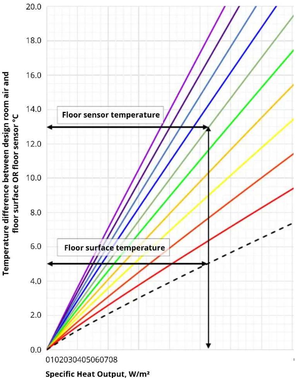
Floor sensor setting for target heat output
line
| Specific Heat Output, W/m² | Temperature difference between design room air and floor surface OR floor sensor °C | | -------------------------- | -------------------------------------------------------------------------------------- | | 0 | 0.0 | | 20 | 1.5 | | 40 | 3.0 | | 60 | 4.5 | | 80 | 6.0 | | 100 | 7.5 | | 120 | 9.0 | | 140 | 10.5 | | 160 | 12.0 | | 180 | 13.5 | | 200 | 15.0 | | 220 | 16.5 | | 240 | 18.0 | | 260 | 19.5 | | 280 | 21.0 |The room with the highest water temperature requirement sets the design water temperature for the whole system based on the calculations from the previous section.
Using the graph above it is possible to limit the specific heat output to the required value.
The example above shows a design room air temperature of 20^ C and design heat output of 52.5 W/m^2 . Based on a 0.150 m^2 K/W (1.5 tog) floor finish the floor sensor should be set to 33^ C ( 20^ C room air + 13^ C T ) to resulting in floor surface temperature of 25^ C ( 20^ C room air + 5^ C T ).
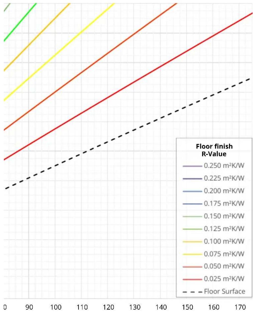
line
| Floor finish R-Value | 0.250 m²K/W | 0.225 m²K/W | 0.200 m²K/W | 0.175 m²K/W | 0.150 m²K/W | 0.125 m²K/W | 0.100 m²K/W | 0.075 m²K/W | 0.050 m²K/W | 0.025 m²K/W | Floor Surface | |----------------------|-------------|-------------|-------------|-------------|-------------|-------------|-------------|-------------|-------------|-------------|---------------| | 0 | ~1.5 | ~1.4 | ~1.3 | ~1.2 | ~1.1 | ~1.0 | ~0.9 | ~0.8 | ~0.7 | ~0.6 | ~1.0 | | 90 | ~2.5 | ~2.4 | ~2.3 | ~2.2 | ~2.1 | ~2.0 | ~1.9 | ~1.8 | ~1.7 | ~1.6 | ~1.8 | | 100 | ~3.5 | ~3.4 | ~3.3 | ~3.2 | ~3.1 | ~3.0 | ~2.9 | ~2.8 | ~2.7 | ~2.6 | ~2.2 | | 110 | ~4.5 | ~4.4 | ~4.3 | ~4.2 | ~4.1 | ~4.0 | ~3.9 | ~3.8 | ~3.7 | ~3.6 | ~2.8 | | 120 | ~5.5 | ~5.4 | ~5.3 | ~5.2 | ~5.1 | ~5.0 | ~4.9 | ~4.8 | ~4.7 | ~4.6 | ~3.4 | | 130 | ~6.5 | ~6.4 | ~6.3 | ~6.2 | ~6.1 | ~6.0 | ~5.9 | ~5.8 | ~5.7 | ~5.6 | ~4.2 | | 140 | ~7.5 | ~7.4 | ~7.3 | ~7.2 | ~7.1 | ~7.0 | ~6.9 | ~6.8 | ~6.7 | ~6.6 | ~5.0 | | 150 | ~8.5 | ~8.4 | ~8.3 | ~8.2 | ~8.1 | ~8.0 | ~7.9 | ~7.8 | ~7.7 | ~7.6 | ~6.0 | | 160 | ~9.5 | ~9.4 | ~9.3 | ~9.2 | ~9.1 | ~9.0 | ~8.9 | ~8.8 | ~8.7 | ~8.6 | ~7.2 | | 170 | >10 | >9.9 | >9.9 | >9.9 | >9.9 | >9.9 | >9.9 | >9.9 | >9.9 | >9.9 | >8 |Specific Heat Output, W/m²

The design floor surface temperature difference should not be more than 9 °C in occupied areas, 15 °C in unoccupied areas.

Heat output is limited by the floor finish resistance combined with the maximum probe setting of 40 °C.

Temperature limits of the floor finish or its adhesive may adversely limit the design heat output.

Warmup plc
www.warmup.co.uk
uk@warmup.com
Tel: 0345 345 2288
Fax: 0345 345 2299


Please scan the QR code to provide feedback on your installation


- Warmup®
- Over 2.5 million installations in more than 72 countries
- Experience MyHeating™
- SmartGeo™
- Easy to use
- AutoSwitch™
- Download now for iOS and Android
- Important installation information
- Warmup plc limited warranty - Hydronic floor heating pipe
- Limited warranty:
- Warranty duration
- The lifetime warranty applies to the pipes(s) if they:
- Register your Warmup® warranty online at www.warmup.co.uk
- Example:
- Warmup plc
Brand : Warmup
Model : VLo Ultra-12
Category : Heating