Bolero E500 (2011) - Motorhome Swift - Free user manual and instructions
Find the device manual for free Bolero E500 (2011) Swift in PDF.


| Product Type | Motorhome |
| Brand | Swift |
| Model | Bolero E500 (2011) |
| Length | 5.99 m |
| Width | 2.3 m |
| Height | 2.9 m |
| Maximum Technical Mass | 3500 kg |
| Base Vehicle | Fiat Ducato |
| Engine | 2.0L Multijet Diesel |
| Power | 100 kW (136 hp) |
| Fuel Tank Capacity | 75 L |
| Fresh Water Tank | 100 L |
| Waste Water Tank | 80 L |
| Number of Berths | 4 |
| Heating System | Truma Combi 4E (gas/electric) |
| Refrigerator | Dometic 3-way (gas/12V/230V) |
| Water Heater | Truma Ultrastore (gas/electric) |
| Electrical System | 12V leisure battery + 230V hook-up |
| Maintenance | Annual service recommended; check gas, water, electrical systems |
| Cleaning | Use mild detergent for exterior; interior with non-abrasive cleaners |
| Safety Equipment | Fire extinguisher, smoke alarm, carbon monoxide detector |
| Spare Parts Availability | Available through Swift dealers or online; common parts for Fiat base |
| General Information | Classic coachbuilt layout with rear island bed and spacious lounge |
Frequently Asked Questions - Bolero E500 (2011) Swift
User questions about Bolero E500 (2011) Swift
0 question about this device. Answer the ones you know or ask your own.
Ask a new question about this device
Download the instructions for your Motorhome in PDF format for free! Find your manual Bolero E500 (2011) - Swift and take your electronic device back in hand. On this page are published all the documents necessary for the use of your device. Bolero E500 (2011) by Swift.
USER MANUAL Bolero E500 (2011) Swift
Swift Group, Dunswell Road, Cottingham, East Yorkshire | IU16 4JS.
Tel: 01482 875740 Fax: 01482 840082
email: enquiry@swiftgroup.co.uk
www.swiftgroup.co.uk
1091960
Issued February 2011
natural_image
Black-and-white landscape photo of a winding road through rocky hills under a cloudy sky (no text or symbols visible)Bolero / E500 Series
Specification, wiring diagrams and bulb chart

natural_image
Plain gray square with a white rounded border (no text or symbols)contents
Standard Specifications 2
Optional Specifications 3
Capacities 4
Towing Capabilities 5
Jacking 6
Wiring Diagrams 7
Bulb Replacement 14
Standard Specifications
| Model Bolero 600EK / E510 Bolero 630PR / E520 Bolero 630EW / E540 Bolero 680FB / E560 | ||||
| Roof Profile Low Profile Low Profile Low Profile Low Profile | ||||
| Engine Fat '100 MultiJet' diesel Fat '130 MultiJet' diesel Fiat '130 MultiJet' diesel Fiat '130 MultiJet' diesel | ||||
| Engine Capacity 2198cc 2287cc 2287cc 2287cc | ||||
| Engine Power | 100bhp @ 2900rpm | 130bhp @ 3600rpm | 130bhp @ 3600rpm | 130chp @ 3600rpm |
| Torque | 250Nm @ 1500rpm | 320Nm @ 2000rpm | 320Nm @ 2000rpm | 320Nm @ 2000rpm |
| Chassis | Flat special low line | Flat special low line | Flat special low line | Flat special low line |
| Wheel base | 3.00m/9'10" | 4.04m/13'3" | 4.04m/13'3" | 4.04m/13'3" |
| Designated Passenger Seats | 1 | 1 | 1 | 1 |
| Berths (sleeping positions) | 2 | 2 | 2 | 4 |
| Overall Length (no ladder)* | 5.90m/19'4" | 7.04m/23'1" | 7.04m/23'1" | 7.04m/23'1" |
| Overall Width (mirrors folded) | 2.31m/7'7" | 2.35m/7'8" | 2.35m/7'8" | 2.35m/7'8" |
| Overall Height | 2.77m/9'1" | 2.77m/9'1" | 2.77m/9'1" | 2.77m/9'1" |
| Maximum Technical Permissible Laden Mass (A) | 3300kg | 3500kg | 3500kg | 3500kg |
| Mass in Running Order (3)† | 2885kg | 3150kg | 3145kg | 3150kg |
| Maximum User Payload (A-B) | 415kg | 350kg | 356kg | 350kg |
| Unlodon Weight | 2629kg | 2894kg | 2889kg | 2894kg |
| Essential Habitation Equipment | 10kg | 10kg | 10kg | 10kg |
| Thermal Insulation Grade | THREE | THREE | THREE | THREE |
| Bed Sizes | ||||
| Front Double | 2.06m x 1.38m/1.24m / 6'9" x 4'6'4'1" | 2.11m x 1.81m/1.33m / 6'11" x 5'11'4'4" | 2.11m x 1.24m/1.06m / 6'11" x 4'1'3'6" | |
| Front Neanside Single | 1.93m x 0.71m / 6'4" x 2'4" | 1.93m x 0.71m / 6'4" x 2'4" | ||
| Front Offside Single | 1.78m x 0.71m / 5'10" x 2'4" | 1.81m x 0.72m / 5'11" x 2'4" | ||
| Rear Double | 2.11m x 1.33m / 6'11" x 4'4" | 1.90m x 1.32m / 6'3" x 4'4" | ||
| Rear Neanside Single | 1.79m x 0.71m / 5'10" x 2'4" | |||
| Rear Offside Single | 1.89m x 0.71m / 6'2" x 2'4" | |||
NOTE: 1. The Maximum User Payload includes: at the conventional load (this is the allowance for passengers)
b) essential habitation equipment (items and fluids required for safe and proper functioning of habitation equipment)
c) optional equipment (items available from the manufacturer over and above the standard specification)
d) personal effects {those items not covered by the above}
2. The Mass in Running Order is the mass of the unladen vehicle including a 75kg allowance for the driver plus engine coolants and 90% of the fuel tank, water tank and gas capacity.
3. PLEASE TAKE CARE TO ENSURE THAT YOU HAVE ALLOWED FOR THE MASSES OF ALL ITEMS YOU INTEND TO CARRY IN THE MOTOR CARWAN,
e.g. passengers, optional equipment, essential habitation equipment and personal effects, such as clothing, food, pets, bicycles, sailboards, sports equipment etc.
4. WARNING - UNDER NO CIRCUMSTANCES SHOULD THE MAXIMUM TECHNICAL PERMISSIBLE LADEN MASS OF THIS MOTOR CARAVAN BE EXCEEDED.
* For optional roof ladder (add 100mm)
Optional Specifications
| Model Bolero 600EK / E510 Bolero 630PR / E520 Bolero 630EW / E540 Bolero 680FB / E560 | ||||
| Roof Profile Low Profile Low Profile Low Profile Low Profile | ||||
| Engine | Flat '130 MultiJet' diesel | Flat '160 MultiJet' diesel Auto | Flat '160 MultiJet' diesel Auto | Flat '160 MultiJet' diesel Auto |
| Engine Capacity 228/cc 2999cc 2999cc 2999cc | ||||
| Engine Power 130chp @ 3000rpm 157chp 157bhp 157chp | ||||
| Torque 320Nm @ 2000rpm 400Nm 400Nm 400Km | ||||
| Chassis | Flat special low line | Flat special low line | Flat special low line | Flat special low line |
| Wheel base | 3.00m/9'10" | 4.04m/13'3" | 4.04m/13'3" | 4.04m/13'3" |
| Designated Passenger Seats | 1 | 1 | 1 | 1 |
| Berths (sleeping positions) | 2 | 2 | 2 | 4 |
| Overall Length (no ladder)* | 5.90m/19'4" | 7.04m/23'1" | 7.04m/23'1" | 7.04m/23'1" |
| Overall Width (mirrors folded) | 2.31m/7'7" | 2.35m/7'8" | 2.35m/7'8" | 2.35m/7'8" |
| Overall Height | 2.77m/9'1" | 2.77m/9'1" | 2.77m/9'1" | 2.77m/9'1" |
| Maximum Technical Penmissible Laden Mass (A) | 3300kg 3500kg 3500kg 3500kg | |||
| Mass in Running Order (3)† | 2900kg 3217kg 3212kg 3217kg | |||
| Maximum User Payload (A-B) | 400kg | 283kg | 288kg | 283kg |
| Unlodon Weight | 2644kg 2961kg 2956kg 2961kg | |||
| Essential Habitation Equipment | 10kg | 10kg | 10kg | 10kg |
| Thermal Insulation Grade | THREE | THREE | THREE | THREE |
| Bed Sizes | ||||
| Front Double | 2.06m x 1.38m/1.24m / 6'9" x 4'6''4'1" | 2.11m x 1.81m / 1.33m / 6'11" x 5'11''4'4" | 2.11m x 1.24m/1.06m / 6'11" x 4'1''3'6" | |
| Front Neanside Single | 1.93m x 0.71m / 6'4" x 2'4" | 1.93m x 0.71m / 6'4" x 2'4" | ||
| Front Offside Single | 1.78m x 0.71m / 5'10" x 2'4" | 1.81m x 0.72m / 5'11" x 2'4" | ||
| Rear Double | 2.11m x 1.33m / 6'11" x 4'4" | 1.90m x 1.32m / 6'3" x 4'4" | ||
| Rear Neanside Single | 1.79m x 0.71m / 5'10" x 2'4" | |||
| Rear Offside Single | 1.89m x 0.71m / 6'2" x 2'4" | |||
NOTE: 1. The Maximum User Payload includes: a) the conventional load (this is the allowance for passengers)
b) essential habitation equipment (items and fluids required for safe and proper functioning of habitation equipment)
c) optional equipment (items available from the manufacturer over and above the standard specification)
d) personal effects (those items not covered by the above)
2. The Mass in Running Order is the mass of the unladen vehicle including a 75kg allowance for the driver plus engine coolants and 90% of the fuel tank, water tank and gas capacity.
3. PLEASE TAKE CARE TO ENSURE THAT YOU HAVE ALLOWED FOR THE MASSES OF ALL ITEMS YOU INTEND TO CARRY IN THE MOTOR CARWAN,
e.g. passengers, optional equipment, essential habitation equipment and personal effects, such as clothing, food, pets, bicycles, sailboards, sports equipment etc.
4. WARNING - UNDER NO CIRCUMSTANCES SHOULD THE MAXIMUM TECHNICAL PERMISSIBLE LADEN MASS OF THIS MOTOR CARAVAN BE EXCEEDED.
* For optional roof ladder (add 100mm).
Capacities
Water Tank Capacities
| Fresh Water Tank | Waste Water Tank | Water Heater | Toilet Tank (Flushing) | |
| Bolero/E500 90 litre 68 litre 10 litre 0 litre |
Gas Capacities
| Capacity | |
| Bolero/E500 | 2 x 7kg |
The above are recommended gas bottle sizes
NOTICE
For technical data on the base vehicle please refer to manufacturer's handbook
Towing Capabilities
Bolero / E500 Series Towing Capabilities
| Model Engine / Chassis MTPLM Permissible | Front Axle Load | Permissible Rear Axle Load | Recommended Maximum Trailer Weight | Gross Train Weight | ||
| Bolero 600EK / E510 100 MJ (2.2L) /SWB / ABS 3300kg 1750kg 1900kg 1400kg 4700kg | ||||||
| Bolero 600EK / E510 130MJ (2.3L) / SWB / ABS 3300kg 1750kg 1900kg 1400kg 4700kg | ||||||
| Bolero 630PR / E520 130MJ (2.3L) / LWB / ABS 3500kg 1850kg 2000kg 1400kg 4900kg | ||||||
| Bolero 630PR / E520 160MJ (3.0L) / LWB / ABS / AUTO 3500kg 1850kg 2000kg 1400kg 4900kg | ||||||
| Bolero 630EW / E540 130MJ (2.3L) /LWB / ABS | 3500kg 1850kg 2000kg 1400kg 4900kg | |||||
| Bolero 630EW / E540 | 160MJ (3.0L) / LWB / ABS / AUTO 3500kg 1850kg 2000kg 1400kg 4900kg | |||||
| Bolero 680FB / E560 | 130MJ (2.3L) /LWB / ABS | 3500kg | 1850kg | 2000kg | 1400kg | 4900kg |
| Bolero 680FB / E560 | 160MJ (3.0L) / LWB / ABS / AUTO 3500kg 1850kg 2000kg 1400kg 4900kg |
To ensure adequate road holding, the load on the front axle, under all conditions, must not be less than 40% or more than 70% of the total weight.
Care must be taken when distributing loads. The loadings and weights above are maximums and must not be exceeded under any circumstances.
CAUTION: When fitting a towbar, it must meet certain minimum requirements as specified by Type Approval Regulations. The bar will have marked on it the approval standard (94/20/EC) and the maximum download, or noseweight, that it can accept. It must fit the manufacturer's approved mounting points and must not obscure the towing vehicle's number plate.
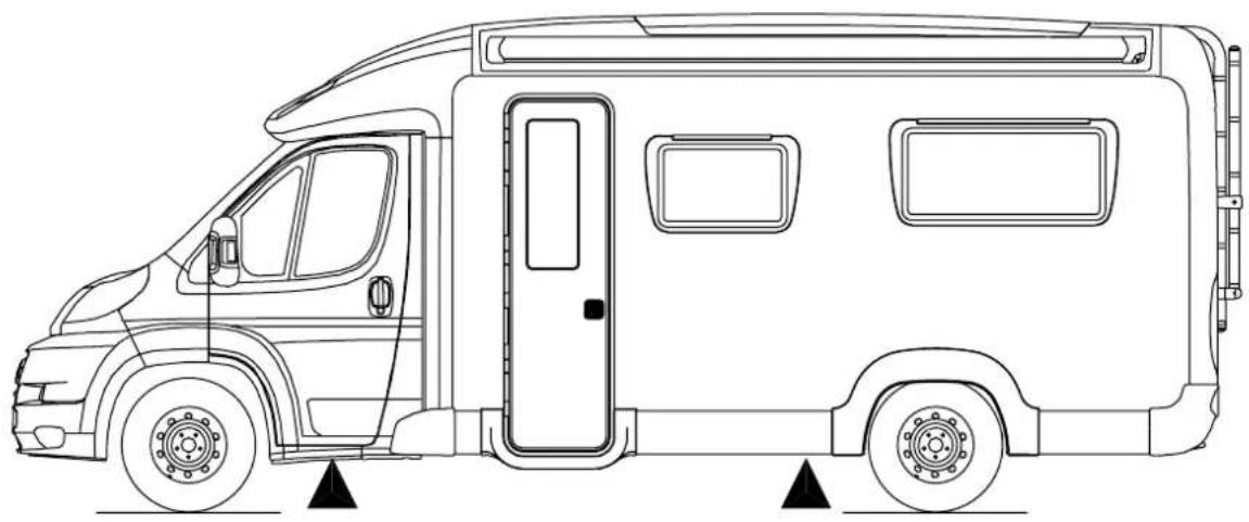
Jacking
sWIFt BoleRo / e500 seRles
natural_image
Side profile line drawing of a two-wheeled vehicle with front door and side panel, showing no text or symbolsJacking Point: ▲
Wiring Diagrams
RoAd IIGHtInG
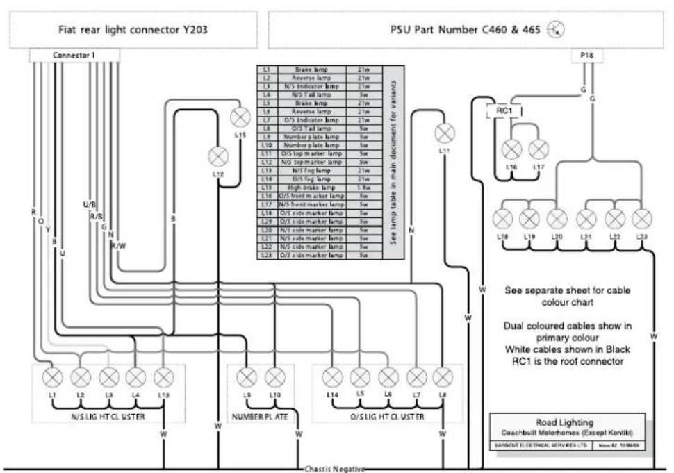
Copyright: Sappati Electrical Services Ltd, 2008 all rights reserved. Subject to change without provisions.
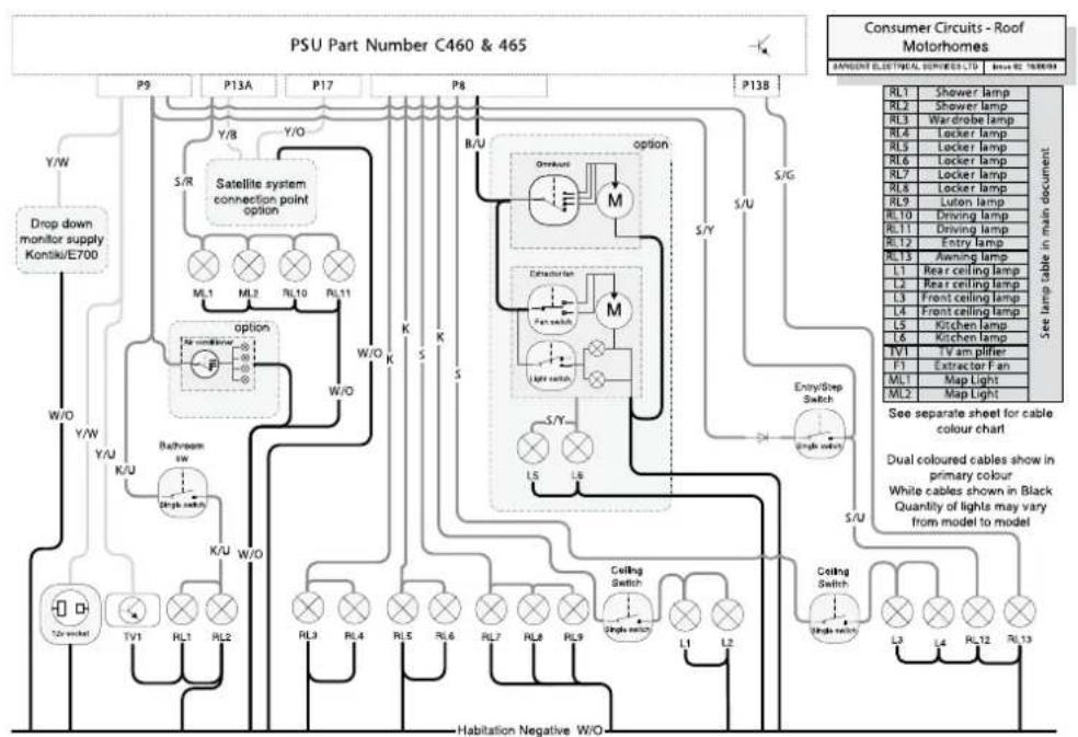
Wiring Diagrams
consUmeR cIRcUlts - RooF
flowchart
graph TD
    A["PSU Part Number C460 & 465"] --> B["P9"]
    A --> C["P13A"]
    A --> D["P17"]
    A --> E["P8"]
    A --> F["P13B"]
    B --> G["Y/W"]
    C --> H["Y/O"]
    D --> I["S/R"]
    E --> J["B/UV"]
    F --> K["S/G"]
    G --> L["Satellite system connection point option"]
    H --> M["Option"]
    I --> N["Concentration"]
    J --> O["Entry/Step Switch"]
    K --> P["Enable Lamp"]
    L --> Q["Shower lamp"]
    M --> R["Wardrobe lamp"]
    N --> S["Locker lamp"]
    O --> T["Leflon lamp"]
    P --> U["Driving lamp"]
    Q --> V["Entry lamp"]
    R --> W["Rear ceiling lamp"]
    S --> X["Rear ceiling lamp"]
    T --> Y["Front ceiling lamp"]
    U --> Z["Front ceiling lamp"]
    V --> AA["Kitchen lamp"]
    W --> AB["Kitchen lamp"]
    X --> AC["Eltractor Fan"]
    Y --> AD["Map Light"]
    Z --> AE["Map Light"]
    AA --> AF["Seal lamp cable in main document"]
    AB --> AG["Seal lamp cable in main document"]
    AC --> AH["Seal lamp cable in main document"]
    AD --> AI["Habitation Negative W/O"]
    AE --> AJ["Habitation Negative W/O"]
    AF --> AK["Habitation Negative W/O"]
    AG --> AL["Habitation Negative W/O"]
    AH --> AM["Habitation Negative W/O"]
    AI --> AN["Habitation Negative W/O"]
Copyright: Sargent Electrical Services Ltd, 2006 all rights reserved. Subject to change without prior notice.
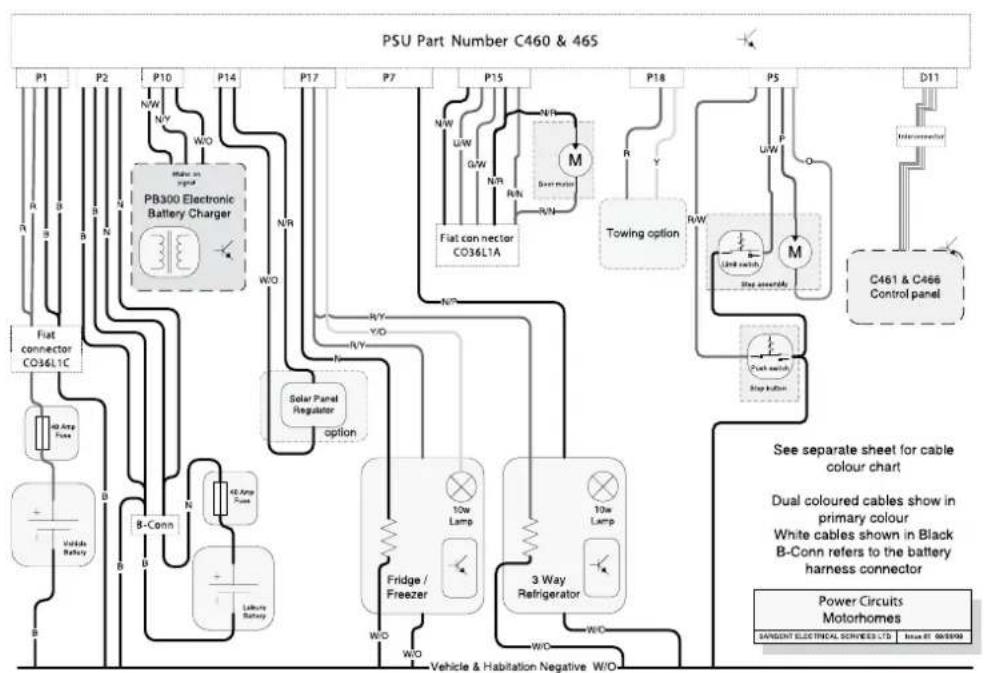
Wiring Diagrams
poWeR cIRcUlts
Copyright: Imperial Electrical Services Ltd, 2008 all rights reserved. Subject to change without prior notice.
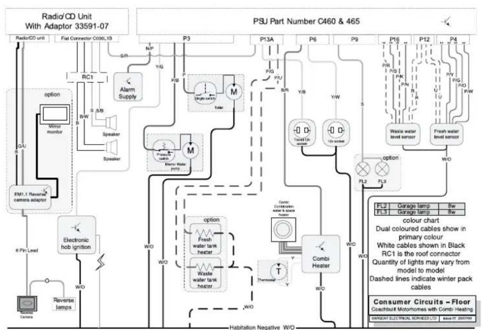
Wiring Diagrams
consUmeR cIRcUlts FlooR WltH comBI HeAtInG
flowchart
graph TD
    A["Radio/CD Unit With Adaptor 33591-07"] --> B["Radio/CD unit"]
    A --> C["Flat Connector C036L1B"]
    B --> D["RS"]
    C --> E["RF"]
    D --> F["Alarm Supply"]
    E --> G["Speaker"]
    F --> H["Alarm Supply"]
    G --> I["Speaker"]
    H --> J["Alarm Supply"]
    I --> K["Sensor"]
    J --> L["Sensor"]
    K --> M["EM1.1 Reverse camera adaptor"]
    L --> N["6 Pin Lead"]
    M --> O["Electronic hob Ignition"]
    N --> P["Reverse lamps"]
    O --> Q["W/O"]
    P --> R["W/O"]
    Q --> S["Habitation Negative W/O"]
    R --> T["W/O"]
    S --> U["W/O"]
    T --> V["Combi Heater"]
    U --> V
    V --> W["W/O"]
    X["PSU Part Number C460 & 465"] --> Y["P3"]
    X --> Z["P13A"]
    X --> AA["P6"]
    X --> AB["P9"]
    X --> AC["P16"]
    X --> AD["P12"]
    X --> AE["P4"]
    X --> AF["P18"]
    X --> AG["P12"]
    X --> AH["P18"]
    X --> AI["P18"]
    X --> AJ["P18"]
    X --> AK["P18"]
    X --> AL["P18"]
    X --> AM["P18"]
    X --> AN["P18"]
    X --> AO["P18"]
    X --> AP["P18"]
    X --> AQ["P18"]
    X --> AR["P18"]
    X --> AS["P18"]
    X --> AT["P18"]
    X --> AU["P18"]
    X --> AV["P18"]
    X --> AW["P18"]
    X --> AX["P18"]
    X --> AY["P18"]
    X --> AZ["P18"]
    X --> BA["P18"]
    X --> BB["P18"]
    X --> BC["P18"]
    X --> BD["P18"]
    X --> BE["P18"]
    X --> BF["P18"]
    X --> BG["P18"]
    X --> BH["P18"]
    X --> BI["P18"]
    X --> BJ["P18"]
    X --> BK["P18"]
    X --> BL["P18"]
    X --> BM["P18"]
    X --> BN["P18"]
    X --> BO["P18"]
    X --> BP["P18"]
    X --> BQ["P18"]
    X --> BR["P18"]
Copyright Surgent Electrical Services Ltd, 2008 all rights reserved. Subject to change without prior notice.
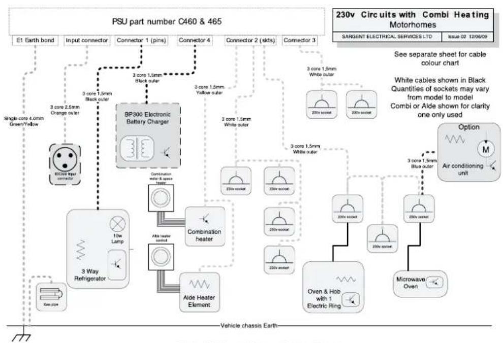
Wiring Diagrams
230v cIRcUlts
flowchart
graph TD
    A["PSU part number C460 & 465"] --> B["E1 Earth bond"]
    A --> C["Input connector"]
    A --> D["Connector 1 (pins)"]
    A --> E["Connector 4"]
    A --> F["Connector 2 (skts)"]
    A --> G["Connector 3"]
    B --> H["BP300 Electronic Battery Charger"]
    C --> H
    D --> H
    E --> H
    F --> H
    G --> H
    H --> I["Combination heater"]
    H --> J["Aldo Heater Element"]
    I --> K["Aided Heater"]
    J --> L["Aided Heater"]
    K --> M["3 core 1.5mm Black outer"]
    K --> N["3 core 1.5mm White outer"]
    K --> O["3 core 1.5mm White outer"]
    K --> P["3 core 1.5mm Black outer"]
    K --> Q["3 core 1.5mm White outer"]
    L --> R["Aided Heater Element"]
    M --> S["Aided Heater"]
    N --> T["Aided Heater"]
    O --> U["Aided Heater"]
    P --> V["Aided Heater"]
    Q --> W["Aided Heater"]
    R --> X["Aided Heater Element"]
    S --> Y["Aided Heater"]
    T --> Z["Aided Heater"]
    U --> AA["Aided Heater"]
    V --> AB["Aided Heater"]
    W --> AC["Aided Heater"]
    X --> AD["Aided Heater"]
    Y --> AE["Aided Heater"]
    Z --> AF["Aided Heater"]
    AA --> AG["Aided Heater"]
    AB --> AH["Aided Heater"]
    AC --> AI["Aided Heater"]
    AD --> AJ["Aided Heater"]
    AE --> AK["Aided Heater"]
    AF --> AL["Aided Heater"]
    AG --> AM["Aided Heater"]
    AH --> AN["Aided Heater"]
    AI --> AO["Aided Heater"]
    AJ --> AP["Aided Heater"]
    AK --> AQ["Aided Heater"]
    AL --> AR["Aided Heater"]
    AM --> AS["Aided Heater"]
    AN --> AT["Aided Heater"]
    AO --> AU["Aided Heater"]
    AP --> AV["Aided Heater"]
    AQ --> AW["Aided Heater"]
    AR --> AX["Aided Heater"]
    AS --> AY["Aided Heater"]
    AT --> AZ["Aided Heater"]
    AU --> BA["Aided Heater"]
    AV --> BB["Aided Heater"]
    AW --> BC["Aided Heater"]
    AX --> BD["Aided Heater"]
    AY --> BE["Aided Heater"]
    AZ --> BF["Aided Heater"]
Copyright Target Electrical Services Ltd, 2000 all rights reserved. Subject to change without prior notice.
Wiring Diagrams
cABle coloUR cHART
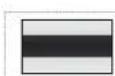
Y/U
Yellow cable with Blue stripe
| Cable Colour Charti ro p | |
| c c c | |
12v Cable Colours
| B | BLACK |
| N | BR OWN |
| R | RED |
| O | OR ANGE |
| Y | YELLOW |
| G | GREEN |
| U | BLUE |
| P | PUR PLE |
| S | SLATE G REY |
| W | WHITE |
| K | PINK |
230v Cable Colours
| B | BLACK |
| N | BROWN |
| W | WHI TE |
| O | ORANGE |
| Y | YELLOW |
| G | GREEN |
| U | BLUE |
Qing y h l l 12 r v g l v 22 v
Bulb Replacement
| Road Lights | ||
| Application Bulb Reference Bulb Rating | ||
| Front marker light W5W 12V 5W | ||
| Side marker light W5W 12V 5W | ||
| Rear high level marker light W5W 12V 5W | ||
| High level stop lamp T5/13.5 12V 2.3W | ||
| Rear indicator lamp PY21 Orange 12V 21W | ||
| Rear Stop / Tail lamp P21/5W 12V 21w / 5W | ||
| Rear reverse lamp P21 12V 21W | ||
| Rear fog lamp P21 12V 21W | ||
| Number plate light C5W 12V 5W | ||
| Interior / Other | ||
| Application | Bulb Rating | |
| Downlighters, LED, main habitation (dry) areas | FEM0470 complete lamp | 12V LED |
| Downlighters, LED, shower (wet) areas | FEM0441 complete lamp | 12V LED |
| Locker spotlights, LED | FEM0440 complete lamp | 12V LED |
| Panel mounted fluorescent lamps | 300mm fluorescent bulb | 12V 8w |
| Panel mounted fluorescent lamps | 600mm fluorescent bulb | 12V 13W |
| Furniture mounted cold cathode fluorescent lamps | 530mm complete lamp, front fixed | 12V 5W CCFL |
| Skylight surround fluorescent lamps | 300mm fluorescent bulb 12V 8W | |
| Ceiling lights, round, single bulb | Halogen capsule | 12V G4 20W |
| Ceiling lights, round, twin bulb | Halogen capsule | 12V G4 10W |
| B-pillar map reading lamps | GU4/MR11 dichroic bulb | GU4 12V 10W |
| Entrance step lamp | LED complete lamp | 12V LED |
| Awning lamp, LED | 500mm LED complete unit | 12V 2.2W LED |
Note: Not all lights feature on all models within a range
Replacement instructions
BoleRo / e500 seRles RoAd IIGHt BUIB Access - ReplAcement InstRUctlons
ReAR IndlcAtoR IAmps And/oR ReveRse IAmps - ReplAcInG
Bulb access is from rear of lamp.
The lamp is retained into the rear panel via a spring clip located at the bottom of the lamp body. To release the lamp:
Carefully insert a large flat bladed screwdriver between the top of the lamp body and the plastic of the rear panel.
Using a lever action push the lamp body down against the spring clip.
Once the spring clip is compressed sufficiently, the top of the lamp body can be withdrawn from the rear panel – with the top of the lamp withdrawn the remainder of the lamp will follow.
At the rear of the lamp, a two part metal clip holds the bulb holder in place. To release this:
Insert a flat bladed screwdriver between the rear of the lamp body and the curved section of the two part clip, and use a lever action to disengage the clip from the rear of the lamp body.
Continue to move the curved section of the clip away from the lamp body, and the second straight part will lift away from the back of the bulb holder.
The bulb holder can now be withdrawn from the lamp body.
Bulbs are a bayonet fitting – apply slight pressure on bulb towards the bulb holder, and twist to release.
Re-position the bulb holder into the lamp body and re-engage the two part clip.
Place the lamp body back into the aperture with the spring clip in position against the edge of that aperture. Using a downward force compress the spring clip until the top edge of the lamp body can also be pushed into the aperture.
stop & tAll Iamps - ReplAcInG
The procedure for these lamps is as for the indicator or reverse lamps.
In addition care is needed when fitting the replacement bulb, that the orientation of the bulb is correct. A simple check is that the lamp when operating as a brake light should be brighter than when operating as a tail lamp, this check can be undertaken before the lamp body is re-fitted into the rear panel.
It is wise to avoid dis-connecting the bulb holder from the harness, as incorrect re-connection can cause the brake / tail operation of the bulb to be reversed, and/or cause a bulb warning light to illuminate on the Fiat dashboard.
ReAR FoG IIGHts
Bulb access is from rear of lamp.
The light fitting can be accessed from underneath the rear of the vehicle.
At the rear of the lamp, twist the bulb holder relative to the lamp body to release, and withdraw the bulb holder and bulb.
Please note: The visible rubber terminal cover is not fixed to the bulb holder, and it may be easier to grip the bulb holder with this removed.
Bulbs are a bayonet fitting – apply slight pressure on bulb towards light fitting, and twist to release.
Re-position the bulb holder into the lamp and twist to lock in place.
Replacement instructions
FRont oR ReAR HIGH level mARkeR / position Iamps (Red / cleAR lense)
Bulb access is from rear of lamp.
Check first within motorhome if rear of lamp is visible If rear of lamp is visible:
Harness plugs into bulb holder – Twist bulb holder relative to lamp body to release bulb holder from lamp body.
Bulbs are push fit into bulb holder – pull bulb directly away from holder to release.
Reverse procedure to replace bulb in holder, holder in lamp and lamp onto motorhome body.
If rear of lamp is not visible:
Remove 2x screws from light fitting, and withdraw whole fitting from motorhome body.
Harness plugs into bulb holder – Twist bulb holder relative to lamp body to release bulb holder from lamp body.
Bulbs are push fit into bulb holder – pull bulb directly away from holder to release.
Reverse procedure to replace bulb in holder, holder in lamp and lamp onto motorhome body.
HIGH level BRAke Iamp
This lamp is single piece and has no user serviceable parts inside.
Remove the screw at both ends of lamp, and withdraw whole fitting away from rear panel of motorhome.
Please note: The screws which retain the lamp also retain the reverse camera housing.
Unplug the lamp from the harness, by squeezing the small tab on the side of the connector, and pulling the connector away from the lamp.
Re-connect the new lamp to harness, and secure with the original two screws.
Lamp retaining screws are fixed into a rubber sleeve with a threaded insert, often known as a rawlnut. If lamp has been removed and re-fitted several times the rubber sleeve may need replacing, these are available through your dealer.
nUmBeR plAte Iamps
Bulb access is via the front lense of each lamp.
Remove the two screws in the lense of the lamp, and remove.
Lever the bulb out of retaining clips.
Reverse the procedure to re-fit a new bulb and the light lens.
slide mARkeR / position Iamps
Bulb access is from rear of lamp.
If rear of lamp is visible from inside the vehicle:
Depending on the location, a small brown plastic cover may be present covering the connections to the lamp. Remove the screws in the cover to release and access the rear of the lamp.
The harness plugs directly into the bulb holder – twist the bulb holder relative to the lamp body to release, and withdraw the bulb holder and bulb.
Bulbs are push fit into bulb holder – pull bulb directly away from holder to release.
Reverse the procedure to replace the bulb in the holder, holder in the lamp and the lamp onto the motorhome body. Replace plastic cover.
If rear of lamp is not visible from inside the vehicle:
Remove the 2 screws from the front of the light fitting, and withdraw the whole fitting from motorhome body.
The harness plugs directly into the bulb holder – twist the bulb holder relative to the lamp body to release, and withdraw the bulb holder and bulb.
Bulbs are push fit into bulb holder – pull bulb directly away from holder to release.
Reverse the procedure to replace the bulb in the holder, holder in the lamp and the lamp onto the motorhome body.
Notes
- Bolero / E500 Series
- Specification, wiring diagrams and bulb chart
- Standard Specifications
- Optional Specifications
- Capacities
- NOTICE
- Towing Capabilities
- Jacking
- Wiring Diagrams
- cABle coloUR cHART
- Y/U
- Yellow cable with Blue stripe
- Bulb Replacement
- Replacement instructions
- BoleRo / e500 seRles RoAd IIGHt BUIB Access - ReplAcement InstRUctlons
- ReAR IndlcAtoR IAmps And/oR ReveRse IAmps - ReplAcInG
- stop & tAll Iamps - ReplAcInG
- ReAR FoG IIGHts
- FRont oR ReAR HIGH level mARkeR / position Iamps (Red / cleAR lense)
- HIGH level BRAke Iamp
- nUmBeR plAte Iamps
- slide mARkeR / position Iamps
Brand : Swift
Model : Bolero E500 (2011)
Category : Motorhome