
EKHWS150BA3V3 - Chauffe-eau et chaudière DAIKIN - Free user manual and instructions
Find the device manual for free EKHWS150BA3V3 DAIKIN in PDF.


| Product Type | Domestic Hot Water Tank for Air-to-Water Heat Pump System |
| Model | EKHWS150BA3V3 |
| Brand | Daikin |
| Volume | 150 Liters |
| Dimensions (Diameter x Height) | 595 x 945 mm |
| Weight (Empty) | 41 kg |
| Mounting Type | Floor Mounted |
| Booster Heater Capacity | 3 kW |
| Booster Heater Power Supply | 230 V 50 Hz 1 Phase |
| Booster Heater Running Current | 13 A |
| Water Connections | 3/4" Female British Standard Pipe (FBSP) |
| Internal Heat Exchanger Volume | 2 Liters |
| Maximum Pressure | 10 bar (pressure relief valve) |
| Ambient Temperature Range (Installation) | 0°C to 35°C |
| Safety Devices | Thermal Protector (reset button), Pressure Relief Valve |
| Accessories Included | Thermistor + 12 m wire, Contactor-fuse assembly, 3-way valve + motor, Installation Manual |
| Installation Requirements | Indoor only, frost-free location, floor leveling |
| Maintenance | Annual check of pressure relief valve; de-lime booster heater as needed |
| Warranty | Subject to proper installation by qualified professional; warranty void if non-Daikin tank used |
Frequently Asked Questions - EKHWS150BA3V3 DAIKIN
User questions about EKHWS150BA3V3 DAIKIN
0 question about this device. Answer the ones you know or ask your own.
Ask a new question about this device
Download the instructions for your Chauffe-eau et chaudière in PDF format for free! Find your manual EKHWS150BA3V3 - DAIKIN and take your electronic device back in hand. On this page are published all the documents necessary for the use of your device. EKHWS150BA3V3 by DAIKIN.
USER MANUAL EKHWS150BA3V3 DAIKIN
Domestic hot water tank for air to water heat pump system
EKHWS150BA3V3
EKHWS200BA3V3
EKHWS300BA3V3
EKHWS200BA3Z2
EKHWS300BA3Z2
2
CONTENTS
Page
Introduction
General information 1
Scope of this manual .... 1
Model identification 1
Accessories
Accessories supplied with the domestic hot water tank.
Installation of the EKHWS domestic hot water tank.
Main components.... 2
Outlook diagram.... 3
Installation guidelines.... 3
Installing the domestic hot water tank.... 3
Connecting the water circuits.... 3
Field wiring....5
Maintenance
Troubleshooting
General guidelines 7
General symptoms....7
Technical specifications
Domestic hot water tank specifications....7

READ THESE INSTRUCTIONS CAREFULLY BEFORE INSTALLATION. KEEP THIS MANUAL IN A HANDY PLACE FOR FUTURE REFERENCE.
IMPROPER INSTALLATION OR ATTACHMENT OF EQUIPMENT OR ACCESSORIES COULD RESULT IN ELECTRIC SHOCK, SHORT-CIRCUIT, LEAKS, FIRE OR OTHER DAMAGE TO THE EQUIPMENT. BE SURE ONLY TO USE ACCESSORIES MADE BY DAIKIN WHICH ARE SPECIFICALLY DESIGNED FOR USE WITH THE EQUIPMENT AND HAVE THEM INSTALLED BY A PROFESSIONAL.
IF UNSURE OF INSTALLATION PROCEDURES OR USE, ALWAYS CONTACT YOUR DAIKIN DEALER FOR ADVICE AND INFORMATION.
THE UNIT DESCRIBED IN THIS MANUAL IS DESIGNED FOR INDOOR INSTALLATION ONLY AND FOR AMBIENT TEMPERATURES RANGING 0°C\~35°C.
INTRODUCTION
General information
Thank you for purchasing this domestic hot water tank.
The EKHWS domestic hot water tank with integrated 3 kW electrical booster heater can be connected to the indoor unit. The domestic hot water tank is available in three sizes: 150, 200 and 300 litre. All models are floor mounted. The 200 and 300 litre models are also available as 400 V versions.
NOTE

Especially for the United Kingdom
For installation of an EKHWSU domestic hot water tank, refer to the installation manual supplied with the tank.
Scope of this manual
This installation manual describes the procedures for unpacking, installing and connecting the EKHWS domestic hot water tanks.
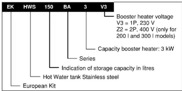
Model identification
ACCESSORIES
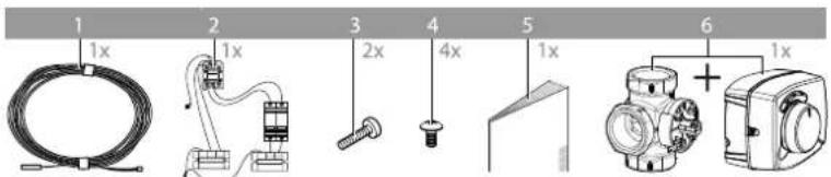
Accessories supplied with the domestic hot water tank
See figure 1
1 Thermistor + connection wire (12 m)
2 Contactor - fuse assembly
3 Contactor fixing screw
4 Tapping screw
5 Installation manual
6 3-way valve + motor
NOTE

For accessories supplied with the EKHWSU domestic hot water tank, refer to the manual supplied with the tank.
INSTALLATION OF THE EKHWS DOMESTIC HOT WATER TANK

The total altherma by DAIKIN system (indoor unit and outdoor unit) is designed for combination with an altherma by DAIKIN domestic hot water tank. In case another tank is being used in combination with the altherma by DAIKIN indoor unit, Daikin cannot guarantee neither good operation nor reliability of the system. For those reasons Daikin cannot give warranty of the system in such case.
■ The equipment is not intended for use in a potentially explosive atmosphere.
■ Domestic hot water quality must be according to EN directive 98/83 EC.
A drain device should be installed on the cold water connection on the domestic hot water tank.
For safety reasons, it is not allowed to add ethylene glycol to the water circuit. Adding ethylene glycol might lead to contamination of the domestic water if a leakage would occur in the heat exchanger coil.
It is important that the storage capacity of the domestic hot water tank meets normal daily fluctuations in consumption of domestic hot water without any fall of the water outlet temperature during use.
Immediately after installation, the domestic hot water tank must be flushed with fresh water. This procedure must be repeated at least once a day the first 5 consecutive days after installation.
In case of limited consumption of domestic hot water, e.g. at holiday residences or at houses that are occasionally not occupied, the domestic hot water tank installation must be fitted with a shunt pump.
■ The shunt pump can be time-controlled,
■ the shunt pump must operate to circulate the complete volume of the domestic hot water tank 1.5 times per hour,
■ and the shunt pump must operate, or be programmed for operation, during 2 uninterrupted hours per day at least.
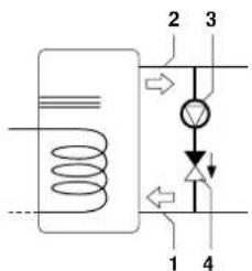
1 Cold water connection
2 Hot water connection
3 Shunt pump (field supply)
4 Non-return valve (field supply)
In case of very long field water piping between the domestic hot water tank and the hot water end point (shower, bath, etc.) it can take more time before the hot water from the domestic hot water tank reaches the hot water end point.
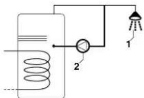
1 Shower
2 Recirculation pump
If required connect a recirculation pump in between the hot water end point and the recirculation hole in the domestic hot water tank.
Following descriptions are only for EKHWS\*V3 and EKHWS\*Z2 models, not for EKHWSU\*V3 models
Main components
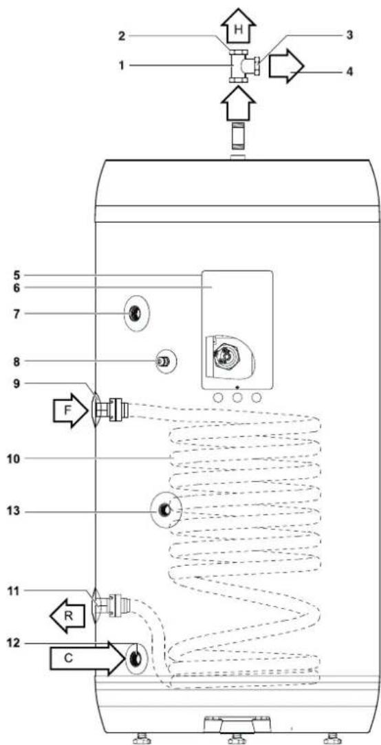
1 Field supply
2 Hot water connection
3 Pressure relief valve connection
4 Pressure relief valve (field supply)
5 Electrical box
6 Electrical box lid
7 Recirculation hole
8 Thermistor socket
9 Flow inlet connection
10 Heat exchanger coil
11 Return outlet connection
12 Cold water connection
13 Threaded thermistor hole
Safety devices

■ The domestic hot water tank relief valve connections may not be used for other purpose.
■ Do not install heaters without thermal cut-outs.
Thermal protector — The booster heater in the domestic hot water tank is equipped with a thermal protector. The thermal protector is activated when the temperature becomes too high. When activated, the protector has to be reset on the domestic hot water tank by pressing the red button (for access, remove the electrical box lid).

The electrical box lid must only be opened by a licensed electrician.
Switch off the power supply before opening the electrical box lid.
■ Pressure relief valve — A pressure relief valve (field supply) in accordance with relevant local and national regulations, and with an opening pressure of maximum 10 bar must be connected to the pressure relief valve connection.
If a discharge pipe is connected to the pressure relief device it must be installed in a continuously downward direction and in a frost-free environment. It must be left open to the atmosphere.
Outlook diagram
Outlook diagram, see figure 2.
1 Hot water and pressure relief valve connection
2 Recirculation hole
3 Flow inlet connection from the main indoor unit
4 Return outlet connection to the main indoor unit
5 Cold water connection
6 Domestic hot water tank electrical box cable entry
7 Thermistor socket
8 Threaded thermistor hole
9 Domestic hot water tank electrical entry (optional)
Domestic hot water tank model H1 H2 H3 H4
| EKHWS150BA3V3 | 945 520 185 650 |
| EKHWS200BA3V3/Z2 | 1195 675 200 875 |
| EKHWS300BA3V3/Z2 | 1645 675 200 875 |
Installation guidelines
Keep in mind the following guidelines when installing the domestic hot water tank:
■ The installation location is frost-free.
■ Make sure to make the piping in size 1" or more (and reduce to 3/4" at the inlet of the tank) as to have sufficient water volume in the piping between indoor unit and domestic hot water tank.
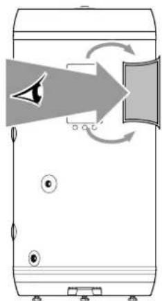
- Locate the domestic hot water tank in a suitable position to facilitate ease of maintenance; remember access is required to the electrical box. Refer to the grey-coloured zones indicated in figure 2.
■ Provide a connection for the pressure relief valve blow-off and drain.
■ To avoid back siphonage it is advised to install a non-return valve on the water inlet of the domestic hot water tank in accordance with local and national regulations.
■ Take care that in the event of a leak, water can not cause any damage to the installation space and surroundings.
Installing the domestic hot water tank
1 Check if all domestic hot water tank accessories (see "Accessories" on page 1) are enclosed.
2 When floor mounting, place the domestic hot water tank on a level surface. Make sure the domestic hot water tank is mounted level.
3 Apply thermal paste to the thermistor and insert the thermistor as deep as possible in the thermistor socket. Fix using the nut provided.
Connecting the water circuits
Refer to the chapter "Typical application examples" described in the installation manual delivered with the indoor unit for details on connecting the water circuits and the motorised 3-way valve.
Connecting the 3-way valve
1 Refer to the figure below before making the connection.
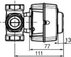
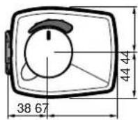
2 Installation position.
It is advised to connect the 3-way valve as close as possible to the indoor unit. It can be installed in accordance with one of the following four configurations.
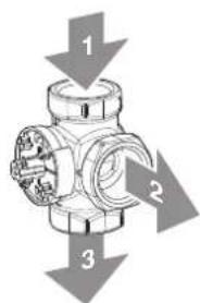
figure A figure B
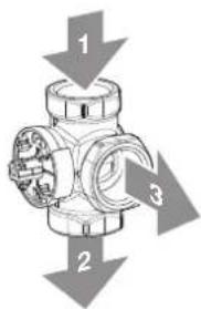
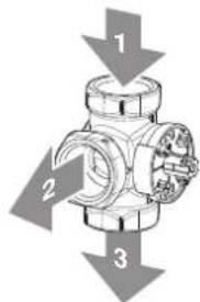
figure C figure D
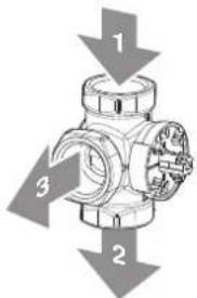
1 From altherma ^* by DAIKIN indoor unit
2 To domestic hot water tank
3 To room heating
3 Unpack the 3-way valve body and 3-way valve motor. Verify that following accessories are provided with the motor.
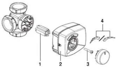
1 Sleeve
2 Valve motor cover
3 Screw
4 Scale
4 Install the 3-way valve body in the pipework.
- Make sure the shaft will be positioned in such a way that the motor can be mounted and replaced.
- Put the sleeve on the valve and turn the valve to the middle position of the scale plate.
Check that the valve is positioned as in the figure below. It should be blocking the outlet connection to the domestic hot water for 50% and the outlet connection to the room heating also for 50%.
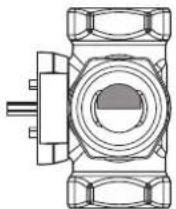
Installation in accordance with figure A and figure B
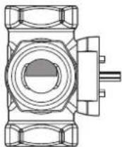
Installation in accordance with figure C and figure D

If the valve is not positioned in this way before mounting the motor, the valve will give way to both domestic water and room heating during operation.
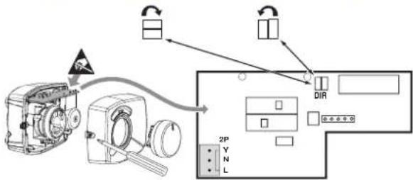
5 When installing in accordance with figure A or figure D, open the valve motor cover by loosening the screw and change the jumper so as to change the rotation direction of the valve.
By default the jumper is factory set to apply for installation in accordance with figure B and figure C.
Installation in accordance with figure A and figure D
Installation in accordance with figure B and figure C
flowchart
graph TD
    A["Camera"] -->|Signal| B["Output"]
    B --> C["DIR"]
    C --> D["2P"]
    D --> E["Y"]
    D --> F["N"]
    D --> G["L"]

Rotation direction of the valve
6 Push the motor on the motor sleeve.
Make sure not to rotate the sleeve during this action, so as to maintain the valve position as set during step 4.
7
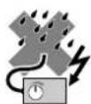

IP41
8 Put the scale on the valve as shown below.
Domestic hot water tank Room heating Room heating
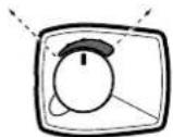
Installation in accordance with figure B and figure C
Domestic hot water tank
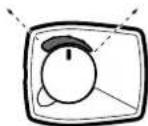
Installation in accordance with figure A and figure D
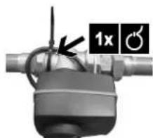
9 Make sure to firmly fix the power supply cord onto the 3-way valve body with a field supplied cable tie like in illustration below.
natural_image
Close-up of a mechanical component with a 1x magnified view and circular symbol (no readable text or symbols)10 Perform the wiring in the indoor unit in accordance with the following figure:
| 8 | 9 | 10 |
| 3-way valve | ||
| BRN | BLU | BLK |
| L | N | Y |
Refer also to the drawing on page 6.
11 Connect the water inlet and water outlet.
12 Connect the hot and cold water supply tubes.
13 Connect the pressure relief valve (field supply, opening pressure maximum 10 bar) and drain.

If a discharge pipe is connected to the pressure relief device it must be installed in a continuously downward direction and in a frost-free environment. It must be left open to the atmosphere.
Field wiring

A main switch or other means for disconnection, having a contact separation in all poles, must be incorporated in the fixed wiring in accordance with relevant local and national legislation.
All field wiring and components must be installed by a licensed electrician and must comply with relevant European and national regulations.
■ The field wiring must be carried out in accordance with the wiring diagram supplied with the unit and the instructions given below.
■ The domestic hot water tank must be earthed via the indoor unit.
Power circuit and cable requirements

■ Be sure to use a dedicated power circuit. Never use a power circuit shared by another appliance.
■ Use one and same dedicated power supply for the outdoor unit, indoor unit, backup heater and domestic hot water tank.
For cable requirements and specifications, refer to "Field wiring" in the indoor unit installation manual supplied with the EKHBH/X unit.
NOTE

Select the power cable in accordance with relevant local and national regulations.

Make sure all field wiring is insulated from the tank body and heater element or can resist temperatures to 90°C.
Thermistor cable
The distance between the thermistor cable and power supply cable must always be at least 5 cm to prevent electromagnetic interference on the thermistor cable.
Procedure for EKHWS\*V3 and EKHWS\*Z2

Switch off the power supply before making any connections.
Connections to be made in the domestic hot water tank electrical box
1 Refer to the wiring diagram sticker in the domestic hot water tank switch box.
natural_image
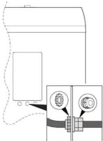
Diagram of a device with speaker and sound waves, no text or symbols present2 Make sure to ensure strain relief of the cable by correct use of the PG nipple and PG nut (mounted on the domestic hot water tank).
Connections to be made in the indoor unit switch box
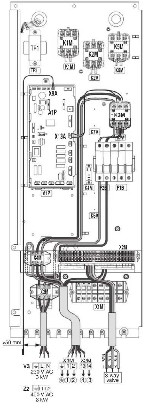
3 Mount the prewired contactor (K3M), circuit breaker (F2B) and terminal blocks (X3M, X4M). The contactor must be fixed with the 2 supplied contactor screws and the terminal blocks must be fixed with the 2x 2 supplied tapping screws.
4 Plug the connector connected to the contactor K3M in the socket X13A on the PCB.
5 Plug the thermistor cable connector in the socket X9A on the PCB.
6 Connect the prewired earth wires of the terminal block X3M and X4M to the earthing screw.
7 Connect the booster heater power supply and thermal protection cable (field supply) to terminal X4M earth, 1, 2, and X2M 13, 14.
8 Connect the booster heater power supply cable to the terminal block X3M.
9 Fix the cables to the cable tie mountings with cable ties to ensure strain relief.
10 Set DIP switch SS2-2 on the PCB to ON.
11 When routing out cables, make sure that these do not obstruct mounting of the indoor unit cover.
Note: only relevant field wiring is shown.
MAINTENANCE
In order to ensure optimal availability of the unit, a number of checks and inspections on the unit and the field wiring have to be carried out at regular intervals.

Before carrying out any maintenance or repair activity, always switch off the circuit breaker on the supply panel, remove the fuses or open the protection devices of the unit.
■ Make sure that before starting any maintenance or repair activity, the power supply to the outdoor unit is switched off too.
The described checks must be executed at least once a year.
1 Domestic hot water tank pressure relief valve (field supply)
Check for correct operation of the pressure relief valve on the domestic hot water tank.
2 Domestic hot water tank booster heater
It is advisable to remove lime buildup on the booster heater to extend its life span, especially in regions with hard water. To do so, drain the domestic hot water tank, remove the booster heater from the domestic hot water tank and immerse in a bucket (or similar) with lime-removing product for 24 hours.
TROUBLESHOOTING
This section provides useful information for diagnosing and correcting certain troubles which may occur in the unit.
General guidelines
Before starting the troubleshooting procedure, carry out a thorough visual inspection of the unit and look for obvious defects such as loose connections or defective wiring.
Before contacting your local dealer, read this chapter carefully, it will save you time and money.

When carrying out an inspection on the supply panel or on the switch box of the unit, always make sure that the circuit breaker of the unit is switched off.
When a safety device was activated, stop the unit and find out why the safety device was activated before resetting it. Under no circumstances safety devices may be bridged or changed to a value other than the factory setting. If the cause of the problem cannot be found, call your local dealer
General symptoms
Symptom 1: No water flow from hot taps
| POSSIBLE CAUSES CORRECTIVE ACTION | |
| The main water supply is off. Check that all shut off valves of the water circuit are completely open. |
Symptom 2: Water from hot taps is cold
| POSSIBLE CAUSES | CORRECTIVE ACTION |
| The thermal cut-out(s) has/have operated | • Check and reset button(s).• Check if thermistor is correctly installed in thermistor socket. |
| The indoor unit (EKHBH/X) is not operating. | Check the indoor unit (EKHBH/X) operation. Refer to the manual delivered with the indoor unit . If any faults are suspected, contact your local dealer. |
Symptom 3: Intermittent water discharge
| POSSIBLE CAUSES | CORRECTIVE ACTION |
| Thermal control failure (water will be hot). | Switch off power to the indoor unit. When discharge has stopped, check the thermal controls and replace if faulty.Contact your local dealer. |
| The expansion vessel is broken. Replace the expansion vessel. | |
TECHNICAL SPECIFICATIONS
Domestic hot water tank specifications
| EKHWS150BA3V3 EKHWS200BA3V3 EKHWS200BA3Z2 EKHWS300BA3V3 EKHWS300BA3Z2 | |||||
| Volume 150 | 200 | 200 | 300 | 300 | Internal heat exchanger volume 2 | I | 3 | I | 3 | I |
| Overall dimensions (Ø x H) | 595 x 945 mm | 595 x 1195 mm | 595 x 1195 mm | 595 x 1645 mm | 595 x 1645 mm |
| Booster heater, power supply | 230 V 50 Hz 1P | 230 V 50 Hz 1P | 400 V 50 Hz 2P | 230 V 50 Hz 1P | 400 V 50 Hz 2P |
| Booster heater, running current | 13 A | 13 A | 7.5 A | 13 A | 7.5 A |
| Booster heater, capacity | 3 kW | 3 kW | 3 kW | 3 kW | 3 kW |
| Connections | 3/4" FBSP^(a) | 3/4" FBSP^(a) | 3/4" FBSP^(a) | 3/4" FBSP^(a) | 3/4" FBSP^(a) |
| Weight (empty) | 41 kg | 48 kg | 48 kg | 61 kg | 61 kg |
| Mounting | Floor | Floor | Floor | Floor | Floor |
(a) FBSP = Female British Standard Pipe

natural_image
Two empty grid paper with no text, numbers, or symbols
natural_image
Two empty grid paper with no text, numbers, or symbols- Domestic hot water tank for air to water heat pump system
- CONTENTS
- INTRODUCTION
- General information
- Scope of this manual
- Model identification
- ACCESSORIES
- Accessories supplied with the domestic hot water tank
- INSTALLATION OF THE EKHWS DOMESTIC HOT WATER TANK
- Following descriptions are only for EKHWS\*V3 and EKHWS\*Z2 models, not for EKHWSU\*V3 models
- Safety devices
- Outlook diagram
- Installation guidelines
- Installing the domestic hot water tank
- Connecting the water circuits
- Connecting the 3-way valve
- Field wiring
- Power circuit and cable requirements
- Thermistor cable
- Procedure for EKHWS\*V3 and EKHWS\*Z2
- Connections to be made in the domestic hot water tank electrical box
- Connections to be made in the indoor unit switch box
- MAINTENANCE
- TROUBLESHOOTING
- General guidelines
- General symptoms
- TECHNICAL SPECIFICATIONS
Brand : DAIKIN
Model : EKHWS150BA3V3
Category : Chauffe-eau et chaudière