
SDGTB06 - Chauffe-eau et chaudière DAIKIN - Free user manual and instructions
Find the device manual for free SDGTB06 DAIKIN in PDF.


| Product Type | Water Heater and Boiler |
| Brand | Daikin |
| Model | SDGTB06 |
| Energy Source | Electric |
| Heating Capacity | 2.0 kW |
| Tank Capacity | 60 liters |
| Dimensions (H x W x D) | 1800 x 600 x 600 mm |
| Weight | 80 kg |
| Thermostat Range | 30°C - 80°C |
| Energy Efficiency Class | A |
| Functions | Heating, Storage, Temperature Control, Frost Protection |
| Safety Features | Overheat Protection, Pressure Relief Valve, Dry Run Protection |
| Maintenance | Drain and descale annually; check anode rod every 2 years |
| Installation | Wall-mounted or floor-standing |
| Spare Parts | Thermostat, Heating Element, Anode Rod, Valves |
| Reparability | Modular design; spare parts available through authorized dealers |
Frequently Asked Questions - SDGTB06 DAIKIN
User questions about SDGTB06 DAIKIN
0 question about this device. Answer the ones you know or ask your own.
Ask a new question about this device
Download the instructions for your Chauffe-eau et chaudière in PDF format for free! Find your manual SDGTB06 - DAIKIN and take your electronic device back in hand. On this page are published all the documents necessary for the use of your device. SDGTB06 by DAIKIN.
USER MANUAL SDGTB06 DAIKIN
R32: Type BDGTA34/41 are not applicable in the EU
3V022006-1A
! Installer must apply for standard installation guidance.

WARNING CAUTIONSE which may cause dangerous situation such as death or severe injury, at the same time, it may cause property damage when mis-operated.

The case which may cause dangerous situation such as injury or minor injury, at the same time, it may cause property damage when mis-operated.
Read through this Installation Manual before installing.

WARNING
- Please perform the installation work, select insulation, and perform heat insulation construction in accordance with the laws and regulations of each country.
- For specifications of connection piping, refer to Table 1 below.
- Piping is limited to newly installed piping.
Even with newly installed piping, remove places to which brazing material is adhered, or which have been burnt by the burner. - Please keep minimum wall thickness of the pipe for installation.
- Do not disassemble the GAS TIGHT JOINT.
- When working in high places, work must be performed with a stable scaffold.
- Carry out the work of connecting the GAS TIGHT JOINT one location at a time, making sure each location is secure. (Do not perform simultaneous work on 2 or more locations between the same outdoor and indoor unit)
- Do not use the GAS TIGHT JOINT which has been dropped.
• The GAS TIGHT JOINT cannot be re-used if it has already been inserted into the piping, temporarily fixed, and removed. - Do not turn the nut in the loosening direction.
Table 1 : Specification of connection piping
Standard
| Model name | Size (O.D.) O60 H58 | Thickness (mm) | ASTM B280 ASTM B88 (Type L) EN12735 | |||||||||
| Same diameter | Different diameter | O60 O50 | H58 | Thickness (mm) R220 | R250 | R290 | Thickness (mm) | |||||
| SDGTB06 | SDGTB0906 | - | 6.35 | ○ | - | 0.762 ± 0.08 | -- | - | ○ | - | - | |
| 0.80 ± 0.08 | ||||||||||||
| SDGTB09 | SDGTB1209 | 9.52 | ○ | - | 0.813 ± 0.08 | ○ | - | 0.762 ± 0.08 | ○ | - | - | |
| ○ | - | - | ||||||||||
| SDGTB12 | SDGTB1512 | 12.7 | ○ | - | 0.813 ± 0.08 | ○ | - | 0.889 ± 0.11 | ○ | - | - | |
| - | ○ | - | ||||||||||
| ○ | ○ | - | ||||||||||
| SDGTB15 | SDGTB1915 | 15.88 | ○ | - | 0.889 ± 0.11 | ○ | - | 1.016 ± 0.11 | - | ○ | - | |
| ○ | ○ | - | ||||||||||
| SDGTB19 | SDGTB2219 | 19.05 | - | ○ | 1.07 ± 0.10 | - | ○ | 1.07 ± 0.11 | ○ | ○ | - | |
| - | ○ | - | ||||||||||
| SDGTB22 SDGTLB22 | SDGTB2522 | 22.22 | - | ○ | 1.14 ± 0.10 | - | ○ | 1.14 ± 0.11 | ○ | - | - | |
| - | ○ | - | ||||||||||
| - | SDGTB2825 | 25.4 * 2 | - | - | - | - | - | - | - | ○ | - | |
| SDGTB3428 | 28.58 | - | ○ | 1.27 ± 0.10 | - | ○ | 1.27 ± 0.13 | - | ○ | ○ | ||
| SDGTB28 SDGTLB28 | 1.25 ± 0.19 | |||||||||||
| - | ○ | - | ||||||||||
| BDGTA34 | - | 34.92 | - | ○ | 1.40 ± 0.15 | - | ○ | 1.40 ± 0.15 | - | ○ | ○ | |
| - | ○ | - | ||||||||||
| BDGTA41 | - | - | 41.28 | - | ○ | 1.52 ± 0.15 | - | ○ | 1.52 ± 0.15 | - | ○ | ○ |
| - | - | ○ | ||||||||||
Notes) 1. “-”: No settings
2. *2 : For connection to the stop valve outlet pipe only.

Removing the thermal insulation material (copper pipe)
1) Be careful not to damage the pipe.
2) If using insulated copper pipe, cut in a cylindrical direction, not in a lengthwise direction.
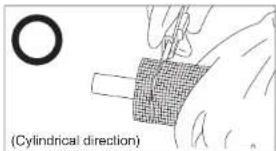
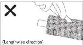

Check the pipe appearance
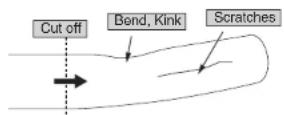
1) If there are scratches, bends, kinks, ovals or thermal aging at the insert part, cut them off.
2) If there are foreign objects, oil, burrs inside and outside of the pipe, remove them.
3) If connecting pipes are covered with oxide films, remove them by a fine sand paper. Do not polish too much.
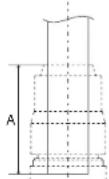
4) For the piping minimum insertion allowance dimension and the maximum long axis side dimension for piping which has been slightly flattened, be sure to follow the dimensions in Table 2.
Table 2 : Minimum insertion allowance and maximum long axis side dimension for piping
| SIZE (O.D.) | A. Piping minimum insertion (mm) | B. Maximum diameter (mm) |
| 6.35 | 20.9 | 6.45 |
| 9.52 | 22.3 | 9.67 |
| 12.7 | 23.9 | 12.85 |
| 15.88 | 36.4 | 16.03 |
| 19.05 | 37.7 | 19.18 |
| 22.22 | 41.2 | 22.32 |
| 25.4 | 42.2 | 25.51 |
| 28.58 | 43.5 | 28.69 |
| 34.92 | 48.9 | 34.99 |
| 41.28 | 49.9 | 41.36 |
GAS TIGHT


The acceptable limit of pipe bend and ovality is that pipe can be inserted to the GAS TIGHT JOINT without force.

CAUTION
Never scratch pipe sections horizontally, as they may cause refrigerant leakage.

Cut the tube to length
1) Use a rotary tube cutter.
2) Ensure that the tube is cut square.
3) Check the pipe has retained its shape and is damage free.
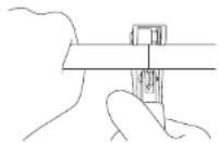

- Cut the pipe slowly to avoid pipe deformation.
- If the rotary tube cutter is damaged or dirty, clean it before use.

Chamfering of the pipe
1) Outside chamfering / Chamfer about 0.5 C
2) Inside chamfering / Deburr the inner part
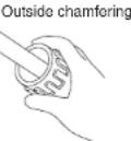
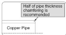
CAUTION
- If no chamfering of the outside of the pipe is performed, the O-ring would be damaged and cause leakage.
- Chamfer the Inside to ensure a proper refrigerant flow rate. The 12.7 pipe contains an Incore. If chamfering of the inside is insufficient, it may cause improper insertion or damage to the internal structure, so be sure to carry out chamfering of the inside.
- Carry out chamfering with the pipe pointing downward, in order to prevent foreign objects from entering the pipe.
In case any foreign objects enter the pipe, remove them.
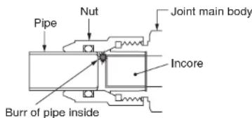

Marking the insertion standard line
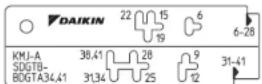
Marking method: using marking gauge
Mark the insertion "T" or "L" standard line with the marking gauge and marker pen at proper position of each pipe size.
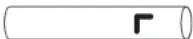

Pipe insertion
1) Insert firmly by hand until the pipe stops.
2) Make sure that the insertion standard line is no longer visible.
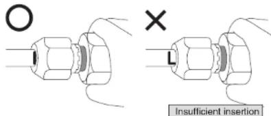

- Insertion the pipe straight.

- Do not tighten the nut before pipe insertion.
- When inserting the pipe, do not apply excessive force. The O-ring will be damaged.
- Do not pull out the tube once it has been inserted. There is a risk of refrigerant leakage due to damage to the pipe, damage to the packing or damage to the incore of 12.7 joint.
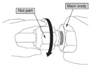
7 Manual tightening of nut
Hold the main body and tighten the nut in the direction of the arrow by hand until it will not turn anymore.
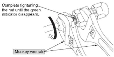
8 Tightening of nut
Hold the main body and tighten the nut with a monkey wrench to the direction of arrow until the green indicator disappears and the nut comes into contact with the flat face of the body.
• In case of insufficient nut tightening, it may cause pipes to come off.
- Excessive tightening prohibited. It may cause joint damage or stress corrosion cracking.
Tighten the nut completely using the same level of torque as the level which is sufficient to overcome the pawls. - Before using the tools, be sure you understand how to use them correctly.
- Do not turn the nut in the loosening direction.
- Do not tighten the joint main body.
⑨ Checking
1) Green indicator should be hidden.
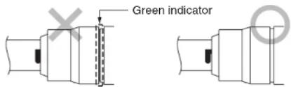
2) Place the marking gauge on the end face of the nut and make sure that the "T" or "L" shaped mark falls completely within the notch in the marking gauge.
The marking gauge contains one notch for measuring the insertion of pipe of 28 or less, and another notch for measuring the insertion of pipe of 31 or more. Be sure you are using the correct notch when measuring.
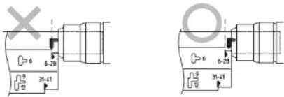
If the "T" or "L" shaped mark falls outside the notch in the marking gauge, cut off the joint, replace it with a new joint, and carry out construction again.
10 Cautions after construction

- Do not apply excessive twisting forces to the GAS TIGHT JOINT after connection.
[Example of work that requires caution]
1) If connecting REFNET joints

- First, connect the GAS TIGHT JOINT to the joint, adjust the orientation of the joint, then carry out connection to the pipe.

• After tightening, do not rotate the joint excessively.
- If connection of the joint is carried out after connection with the pipe, when the GAS TIGHT JOINT is tightened, the joint will turn along with it, so it may be difficult to construct on a horizontal plane.
- Before insulating, check according to step 9 Checking.
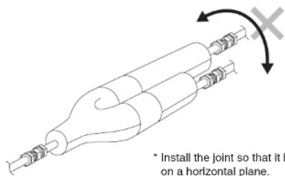
* Install the joint so that it branches on a horizontal plane.
2) If connecting bent pipe
- First, connect the GAS TIGHT JOINT to the bent pipe side, then carry out connection to the pipe.
- After tightening, do not change the direction of the pipe excessively or twist.
- If connection of the bent pipe is carried out after connection with the pipe, the bent pipe will turn along with the pipe, so it may be difficult to construct in an aligned manner.
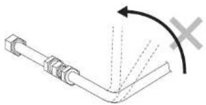
natural_image
Pure mechanical diagram showing a bent pipe with dashed lines indicating motion, no text or symbols present3) Do not apply bending stress to pipes which have already been connected to the GAS TIGHT JOINT.
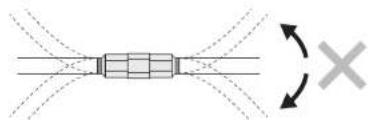
natural_image
Pure diagram of a rectangular object with internal grid pattern and directional arrows, no text or symbols present4) Do not re-use GAS TIGHT JOINTS which have been used previously. Replace the joint with a new one, then re-connect. Regarding the pipe, carry out work in steps ② to ⑤ once again.
11 Gas tightness test
Follow the equipment manufacturer's manual.
In case soldering near the GAS TIGHT JOINT, keep a distance more than 200mm away from the GAS TIGHT JOINT and prevent the heat transfer by using a wet cloth. In case heat transfer is not prevented, the O-ring in the GAS TIGHT JOINT would be thermal aged and leakage would happen.
- Keep the GAS TIGHT JOINT at a temperature of 130°C or less.
- Do not connect to the GAS TIGHT JOINT at bent part of the pipe with pipe bender since the part may have scratches.
12 The insulation process
1) Before Insulation
2) Stick the GAS TIGHT JOINT's insulator (local procurement) and pipe's insulator with insulating tape or seat. (Parts, Please local procurement.)
- At straight joint
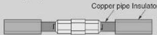

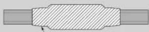
Fix with insulating tape or seat without any clearance.
- At L-shaped joint
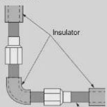
Copper pipe

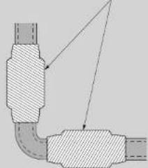
natural_image
Technical diagram of a pipe elbow joint with hatched areas indicating material sections (no text or labels)- If any gaps in the insulation exist, condensation may form and water may drip.
- ! Installer must apply for standard installation guidance.
- Read through this Installation Manual before installing.
- WARNING
- Removing the thermal insulation material (copper pipe)
- Check the pipe appearance
- Cut the tube to length
- Chamfering of the pipe
- CAUTION
- Marking the insertion standard line
- Pipe insertion
- Manual tightening of nut
- Tightening of nut
- ⑨ Checking
- Cautions after construction
- Gas tightness test
- The insulation process
Brand : DAIKIN
Model : SDGTB06
Category : Chauffe-eau et chaudière