
K-1775-3-EWP - Access Control System VIKING - Free user manual and instructions
Find the device manual for free K-1775-3-EWP VIKING in PDF.


| Product Type | Access Control System (Keypad and Card Reader) |
| Brand | Viking |
| Model | K-1775-3-EWP |
| Dimensions (approx.) | 120 mm x 80 mm x 20 mm |
| Weight (approx.) | 150 g |
| Power Supply | 12V DC, 500 mA (external transformer) |
| Interface | Wiegand or RS-485 output |
| Keypad Type | 12-key backlit keypad |
| Card Reader Technology | 125 kHz proximity or 13.56 MHz MIFARE |
| User Capacity | Up to 2000 users (PIN + card) |
| Operating Temperature | -20°C to +60°C |
| Enclosure Rating | Weatherproof (IP65) for outdoor use |
| Mounting Type | Flush mount or surface mount |
| Main Functions | Keypad entry, proximity card access, dual authentication mode, programmable output relay |
| Maintenance & Cleaning | Wipe with a soft, damp cloth; do not use harsh chemicals |
| Safety Features | Tamper switch, lockout after 5 incorrect attempts, anti-passback option |
| Spare Parts & Repairability | Replaceable keypad overlay, reader module, and control board; contact Viking support |
| Included Accessories | Mounting kit, weather gasket, screws, user manual (8 pages) |
| Compliance | FCC, CE, UL listed |
Frequently Asked Questions - K-1775-3-EWP VIKING
User questions about K-1775-3-EWP VIKING
0 question about this device. Answer the ones you know or ask your own.
Ask a new question about this device
Download the instructions for your Access Control System in PDF format for free! Find your manual K-1775-3-EWP - VIKING and take your electronic device back in hand. On this page are published all the documents necessary for the use of your device. K-1775-3-EWP by VIKING.
USER MANUAL K-1775-3-EWP VIKING
Vandal Resistant Entry Phones with Built-In Keypad, Proximity Card Reader, and Color Video Camera
The K-1775-3 Series entry phones provide a tough and attractive handsfree phone for commercial, apartment, and residential door entry or applications requiring a vandal resistant speaker phone with built-in 125 KHz Proximity Card Reader and analog Color Video Camera. The card reader outputs industry standard 26-bit Wiegand data, allowing it to be used with a Viking ES-1 or C-4000 door controller or any controller compatible with 26-bit Wiegand format. The K-1775-3 Series entry phones are available in two attractive finishes: "brushed stainless steel" and "oil rubbed bronze".
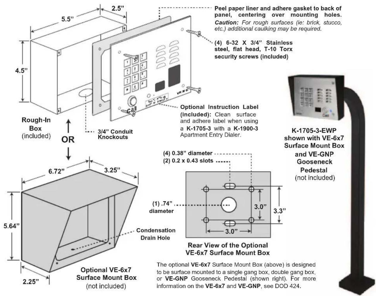
When the "Call" button is pressed, the K-1775-3 returns dial tone. The keypad may then be used to dial any number. If no Touch Tone is entered within 8 seconds, CPC is detected, a busy signal is detected, or the programmable maximum call time has elapsed, the K-1775-3 will automatically disconnect. Alternatively, the K-1775-3 may be disconnected by pressing the "Call" button again. The K-1775-3 provides CCTV video of the entry area and comes complete with a standard, flush mount, rough-in box. In addition, an optional VE-6x7 weather resistant, surface mount box is available (see DOD 424).
Features
• Built-in 125KHz 26-bit Wiegand proximity card reader with LED and beep card read confirmation and EWP board protection
- Built-in high resolution analog NTSC color video camera with wide viewing angle, tilt/swivel adjustments, and operating temperature of -40^ to 140^
• Audio and video transmission on one CAT5E cable (see page 6)
- Compatible with the following Viking Proximity Cards and Fobs: PRX-C, PRX-C-ISO and PRX-FOB (DOD 198)
- Vandal Resistant Features: 14 gauge louvered 316 stainless steel faceplate with permanent laser etched graphics, stainless steel "Call" button, heavy duty metal keypad and T-10 Torx security screws, scratch resistant powder coating (K-1775-3-BN)
- Weather Resistant Features: Marine grade 316 stainless steel faceplate, screws and and push button switch. Switch internally sealed per IP67. Mylar speaker. Self-draining mic mount. Faceplate, mic and speaker gaskets. Weather Resistant powder paint (K-1775-3-BN)
- K-1775-3-EWP is designed to meet IP66 Ingress Protection Rating (see DOD 859 for more information)
• Available in 2 standard faceplate finishes: 316 brushed stainless steel or oil rubbed bronze powder paint
- Blue "in use" LED
- Telephone line powered
• Volume adjustments for microphone and speaker
- Advanced call progress detection: disconnects on busy signal, return to dial tone, CPC, reorder tone, maximum call time out and 40 second silence time out
- Selectable auto-answer feature for monitoring
- Zinc plated steel rough-in box with (2) 3/4" conduit knockouts
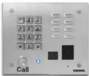
K-1775-3
"Brushed Stainless Steel" (similar to brushed nickel)
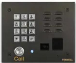
K-1775-3-BN
"Oil Rubbed Bronze"
(satin dark brown powder paint with fine copper metallic)
The K-1775-3-EWP shares all of the features of the K-1775-3 in addition to Enhanced Weather Protection (EWP) for outdoor installations where the unit is exposed to precipitation or condensation. EWP products feature foam rubber gaskets and boots, sealed connections, gel-filled butt connectors, as well as urethane or thermal plastic potted circuit boards with internally sealed, field-adjustable trim pots and DIP switches for easy on-site programming. For more info, see DOD 859.
Applications
- Apartment entry phone when used with the K-1900-3 Apartment Entry Dialer or C-4000 Apartment/Office Entry Controller or C-3000 Apartment Entry Controller
- Use with a Viking C-500 to control 1 or 2 (expandable to 8) K-1775's and door/gate control on a single phone line (DOD 177)
- Use with a Viking C-2000B to control 1 to 4 K-1775's and door/gate control on a single phone line (DOD 156)
• Courtesy and customer assistance phone
• Automated teller (ATM) phone - Use with a Viking ES-1 for proximity card reader door control
- Provide unique front and back door chimes and paging when use with a Viking SLP-1 or SLP-4 and C-2000B
- Kiosk phone with (100 number speed dialing) when used with the K-1900-9 Multi-Number Dialer (DOD 321)
- Use with Viking's Proximity Cards: PRX-C, PRX-C-ISO, PRX-FOB (DOD 198)
Specifications
Dimensions: Overall: 5.5" x 6.5" x 2.6" (140mm x 165mm x 66mm),
Rough-in box: 4.5" x 5.5" x 2.5" (114mm x 140mm x 64mm)
Shipping Weight: 3.5 lbs (1.6 kg)
Environmental: -30^ F to 150^ F ( -34^ C to 65^ C)
Humidity - K-1775-3: 5% to 95% non-condensing
Humidity - K-1775-3-EWP: Up to 100% condensing
(see page 2 for complete specifications)
Specifications
ENTRY PHONE SPECIFICATIONS
Power: Telephone line powered 20V DC/20mA minimum
Dimensions: Overall: 140mm x 165mm x 66mm (5.5" x 6.5" x 2.6"), Rough-in box: 114mm x 140mm x 64mm (4.5" x 5.5" x 2.5")
Shipping Weight: 1.6 kg (3.5 lbs)
Environmental: -29°C to 54°C (-20°F to 130°F)
Humidity - K-1775-3: 5% to 95% non-condensing
Humidity - K-1775-3-EWP: Up to 100% condensing
Speaker Volume: Approximately 70 db maximum @1m
Connections: Gel-filled tip and ring connectors
CPC Disconnect Time: 500ms minimum
REN #: 0.5 A
CAMERA SPECIFICATIONS
Power: 6-22V DC 150mA (12V DC UL Listed adapter included)
Image Sensor: 1/4" color CMOS
Video Output: 1 VP-P composite, NTSC, 75 ohms
Resolution: 420 lines (640 x 480 @ 30fps / 307,200 pixels)
Sensitivity: 0.025 LUX (50 IRE) F 1.2 3200K
Lens: 2.1mm, conical pinhole
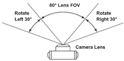
FOV(Field of View): 80° Horizontal, 60° Vertical, 100° Diagonal
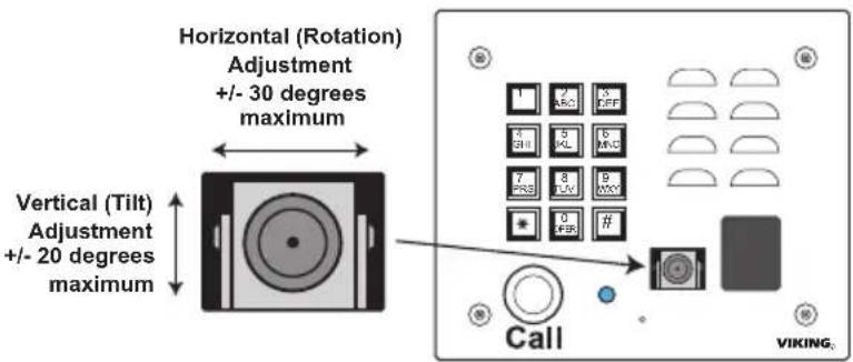
Tilt/Swivel Adjustment: Vertical +/- 20°, horizontal +/- 30° (see Diagram A right)
IR Compatibility: This camera is equipped with an OLP (Optical Low Pass) filter to maintain correct video color in outside applications. The standard camera is NOT compatible with IR illuminators. If IR illumination is required, you will need to replace the existing camera with a Viking model VCAM-1IR, see DOD# 190.
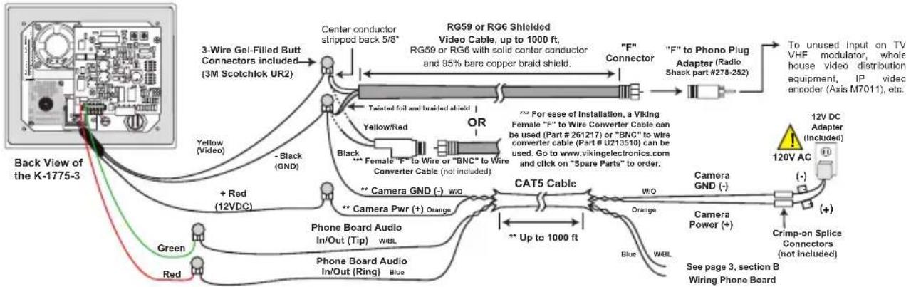
Maximum Wire Run Length: 1000 ft with *RG59/RG6 for video and CAT5 for power (1 pair) and entry phone audio (1 pair). 150 ft with CAT5E for video, power and entry phone audio (longer video runs are possible by using video balun transceivers, see Installation section F, page 6).
PROXIMITY CARD SPECIFICATIONS
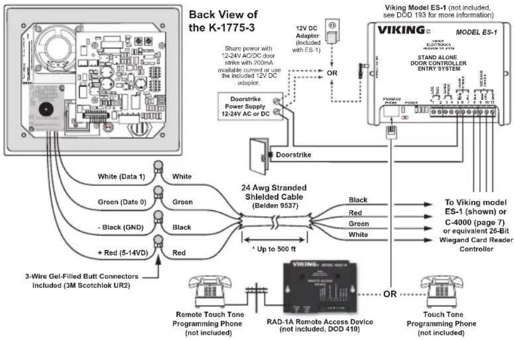
Power: 5 to 14V DC @ 60mA maximum
Maximum Cable Length: 500 ft 24 Awg stranded shielded (Belden 9537)
Frequency: 125KHz
Format: 26 bit Wiegand
Read Range: 1.25" to 2.0"
Technologies Supported: Viking PRX-C, PRX-C-ISO, PRX-FOB, certain legacy HID® proximity protocols** and certain AWID 125Khz proximity protocols***
Transducer: Beeps during card read
LED: Red, turns off during card read
Humidity: Up to 100% (fully potted EWP)
Operating Temperature: -34^ C to 65^ C ( -30^ F to 150^ F)
* Note: RG59 or RG6 with solid center conductor and 95% bare copper braid shield.
** HID and the HID logo are registered trademarks of HID Global Corporation, an ASSA ABLOY company. All other trademarks are the property of their respective owners.
*** AWID is a trademark of Applied Wireless Identification Group.
Diagram A
Camera Horizontal Field of View:
Features Overview
Faceplate Material: 14 gauge 316 stainless steel. The SS model has a #4 brushed finish, the BN models have a powder painted finish.
Color Video Camera: Wide operating temperature range of -40°F to 140°F, NTSC composite video output with 420 lines of resolution, 80° wide viewing angle lens, tilt and swivel adjustments for aiming towards visitors.
Protective Camera Window: Impact resistant polycarbonate lens with scratch resistant coating and water-tight gasket.
Blue Call LED: Lights steady to help locate the button in low light, flashes during dialing, then lights steady when answered.
Push Button Switch: Push to initiate call, push again to disconnect. Solid 316 stainless steel internally sealed per IP67.
Front View of the K-1775-3 Entry Phone
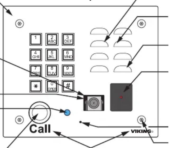
Laser Etched Graphics: For long lasting easy to read graphics (Copper Metallic on model K-1775-BN-3).
Speaker: Mylar speaker with rubber gasket to maintain water-tight seal and eliminate water deterioration.
Speaker Screen: Speaker screen with 0.018" wide slots to prevent punctures from paperclips, etc.
Microphone: Omni-directional microphone with protective water-resistant cloth.
Proximity Card Reader: 26-bit Wiegand, 125KHz, red LED turns off and transducer will beep during card read. Fully potted EWP. Read range 1.25" to 2.0". Impact resistant polycarbonate lens with water-tight gasket.
Condensation Drain Hole
Mounting Screws: (4) 6-32 X 3/4" Marine grade 316 stainless steel, flat head, T-10 Torx security screws and drive bit (included).
A. Mounting
B. Wiring the K-1775-3
* Note: When installing a line powered phone on a low voltage and/or low loop current phone system extension, a TBB-1B Talk Battery Booster may be required (DOD# 632).
*** Note: To increase surge protection, loosen the PCB mounting screw labeled ⏻ (shown right) and fasten a wire with spade terminal (included) from the mounting screw to Earth Ground (grounding rod, water pipe, etc.)
To Optional Viking Entry Controllers (not included)
| Model DOD# Description |
| C-500 177 Advanced 2 Door Controller |
| C-2000B 156 Advanced 4 Door/Gate Entry Phone Controller |
| C-3000 162 Multi-Tenant Entry System |
| C-4000 164 Apartment/Office Entry Controller |
| K-1900-3 312 Apartment Entry Dialer |
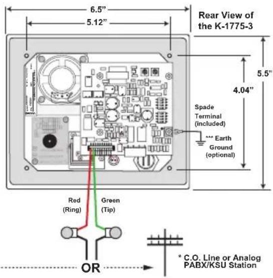
** Note: The gel-filled (water-tight) butt connectors are designed for insulation displacement on 19-26 gauge wire with a maximum insulation of 0.082 inches. Cut off stripped wire ends prior to terminating.
C. Wiring the K-1775-3 Proximity Card Reader
flowchart
graph TD
    A["Back View of the K-1775-3"] --> B["White (Data 1)"]
    A --> C["Green (Date 0)"]
    A --> D["- Black (GND)"]
    A --> E["+ Red (5-14VD)"]
    B --> F["White"]
    C --> G["Green"]
    D --> H["Black"]
    E --> I["Red"]
    F --> J["24 Awg Stranded Shielded Cable (Belden 9537)"]
    G --> J
    H --> J
    I --> J
    J --> K["Black"]
    J --> L["Red"]
    J --> M["Green"]
    J --> N["White"]
    K --> O["To Viking model ES-1 (shown) or C-4000 (page 7) or equivalent 26-Bit Wiegand Card Reader Controller"]
    L --> O
    M --> P["Touch Tone Programming Phone (not included)"]
    N --> Q["Handheld Device (not included, DOD 410)"]
    O --> R["Viking Model ES-1 (not included, see DOD 193 for more information)"]
    P --> S["Handheld Device (not included, DOD 410)"]
    Q --> T["Handheld Device (not included, DOD 410)"]
Camera Wiring and Adjustments

IMPORTANT: Electronic devices are susceptible to lightning and power station electrical surges from both the AC outlet and the telephone line. It is recommended that a surge protector be installed to protect against such surges.
A. Using RG59 for Video and CAT5 for Camera Power and Phone Board Audio (Recommended)
flowchart
graph TD
    A["Back View of the K-1775-3"] --> B["3-Wire Gel-Filled Butt Connectors included (3M Scotchlok UR2)"]
    B --> C["Center conductor stripped back 5/8°"]
    C --> D["RG59 or RG6 Shielded Video Cable, up to 1000 ft, RG59 or RG6 with solid center conductor and 95% bare copper braid shield."]
    D --> E[""F" Connector"]
    E --> F[""F" to Phono Plug Adapter (Radio Shack part #278-252)"]
    F --> G["To unused Input on TV VHF modulator, whole house video distribution equipment, IP video encoder (Axis M7011), etc."]
    C --> H["Twisted foil and braided shield"]
    H --> I["For ease of Installation, a Viking Female "F" to Wire Converter Cable can be used (Part # 261217) or "BNC" to wire converter cable (Part # U213510) can be used. Go to www.vikingelectronics.com and click on "Spare Parts" to order."]
    I --> J[""Camera GND (-)" w/o"]
    J --> K["Up to 1000 ft"]
    K --> L["Camera Power (+)"]
    L --> M["Crimp-on Splice Connectors (not Included)"]
    M --> N["See page 3, section B Wiring Phone Board"]
    C --> O["Yellow/Red Black *** Female "F" to Wire or "BNC" to Wire Converter Cable (not included)"]
    O --> P["Camera Pwr (+) Orange"]
    P --> Q["Phone Board Audio In/Out (Tip) w/BL"]
    Q --> R["Phone Board Audio In/Out (Ring) Blue"]
    R --> S["Green Red"]
    S --> T["+ Red (12VDC)"]
    T --> U[""Yellow (Video)"]
    U --> V["Back View of the K-1775-3"]
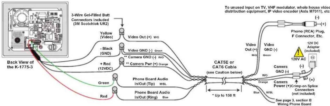
B. Using CAT5E OR CAT6 for Video, Camera Power and Phone Board Audio (see Caution below)
flowchart
graph TD
    A["Back View of the K-1775-3"] --> B["3-Wire Gel-Filled Butt Connectors included (3M Scotchlok UR2)"]
    B --> C["Yellow (Video)"]
    B --> D["Green"]
    B --> E["Red"]
    B --> F["+ Red (12VDC)"]
    B --> G["Blue"]
    B --> H["White"]
    B --> I["White Out (+) w/g"]
    B --> J["Video GND (-) Green"]
    B --> K["Camera GND (-) w/o"]
    B --> L["Camera Pwr (+) Orange"]
    B --> M["Phone Board Audio In/Out (Tip) wBL"]
    B --> N["Phone Board Audio In/Out (Ring) Blue"]
    B --> O["Image to CAT5E or CAT6 Cable (see Caution below)"]
    O --> P["Video Out (+) w/g"]
    O --> Q["Video GND (-) Green"]
    O --> R["Camera GND (-) w/o"]
    O --> S["Orange"]
    O --> T["Blue"]
    O --> U["W/BL"]
    O --> V["Crimp-on Splice Connectors (not included)"]
    O --> W["See page 3, section B Wiring Phone Board"]
    style A fill:#f9f,stroke:#333
    style P fill:#ccf,stroke:#333
    style Q fill:#ccf,stroke:#333
    style R fill:#ccf,stroke:#333
    style S fill:#ccf,stroke:#333
    style T fill:#ccf,stroke:#333
    style U fill:#ccf,stroke:#333
    style V fill:#ccf,stroke:#333
* Note: Up to 150 ft video cable run length can be achieved using CAT5E or CAT6 cable. Longer cable runs can be used if a passive or active video Balun transceiver is used on each end of the cable. Generally, passive transceivers can achieve up to 750 ft cable runs where active transceivers can achieve up to 3000 ft runs depending on cable type, etc. The type of video balun transceiver required is specific to your cable run length. For more information on video balun transceivers go to: www.northernvideo.com.
** Note: The maximum camera power supply wire run length is 1000 ft of 24 gauge wire (CAT 5/6), longer runs are possible by doubling pairs, increasing the wire gauge or using up to a 22V DC 200mA power adapter.
Caution: When routing CAT5E or CAT6 cable, maintain a minimum distance of 3 ft from any parallel high voltage wire (110 VAC) and a minimum of 2 ft from crossing any high voltage wire. For installations where RF noise is expected (commercial applications) or wire runs are near high voltage (110 VAC) wires, a shielded video cable such as RG6 is recommended.
C. Using a Video Encoder to Convert the Analog NTSC Video to IP
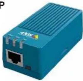
Axis manufactures video servers that encode analog video signal for transmission across IP network or the internet. The single channel model M7011 is shown. Supplied software allows you to access Axis units connected to the network (auto-discovery) and program them via a web page interface. The video can then be monitored from any location on the network.
For more information, go to www.axis.com
natural_image
Blue industrial network device with Ethernet port and ventilation slots (no visible text or symbols)Axis Model M7011 shown
D. Adjusting the Camera
The camera can be tilted and rotated to your desired position. A portable service (test) monitor can be used to determine the correct viewing angle during installation.
Important: To prevent the edge of the faceplate from being viewed in the video image, do not rotate the camera beyond 30 degrees or tilt beyond 20 degrees.
Programming
A. DIP Switches
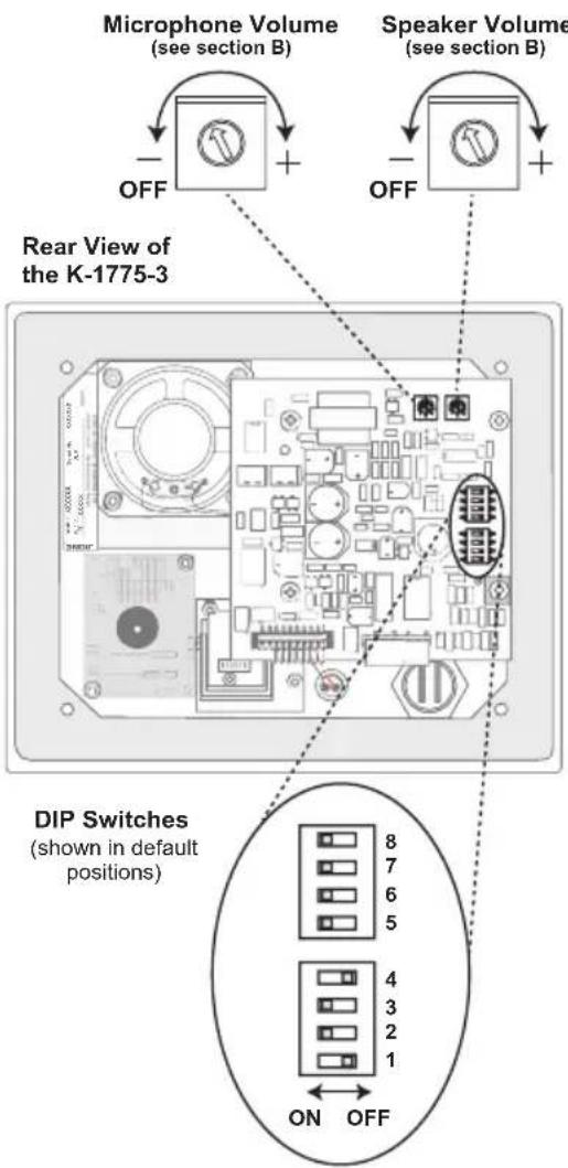
| Switch 1 | Switch 2 M | Maximum Call Time |
| OFF OFF | Disabled | |
| ON OFF | 1 Minute | |
| OFF ON | 3 Minutes | (default) |
| ON ON | 9 Minutes | |
| Switch 3 | Disconnect on Dial Tone | |
| OFF Off | ||
| ON On (default) | ||
| Switch 4 | VOX Switching Speed | |
| OFF Fast, 0.2 sec. (default) | ||
| ON Slow, 0.7 seconds | ||
| Switch 5 | Switch 6 Audio Detection | |
| ON ON | Normal Audio detection | |
| OFF OFF | Increase audio detect sensitivity for low level lines. Useful in applications in which voice or busy signals have trouble breaking over the speaker. | |
| Switch 7 | Auto Answer Position | |
| OFF | Automatic answer disabled | |
| ON Automatic answer enabled (default) | ||
| Switch 8 | Push Button Feature | |
| OFF | Connects calls only | |
| ON Connects/disconnects calls (default) | ||
| Switch 3 | Disconnect on Dial Tone |
| OFF Off | |
| ON On(default) | |
| Switch 4 VOX Switching Speed |
| OFF Fast, 0.2 sec. (default) |
| ON Slow, 0.7 seconds |
| Switch 5 | Switch 6 | Audio Detection |
| ON ON | Normal | Audio detection |
| OFF OFF | Increase audio detect sensitivity for low level lines. Useful in applications in which voice or busy signals have trouble breaking over the speaker. |
| Switch 7 | Auto Answer Position |
| OFF | Automatic answer disabled |
| ON | Automatic answer enabled (default) |
| Switch 8 | Push Button Feature |
| OFF | Connects calls only |
| ON Connects/disconnects calls (default) | |
B. Volume Adjustments
1. Microphone
Certain noisy locations (background traffic, machinery or wind) may cause one way talk path (only microphone audio is heard). In this case, the microphone volume may need to be decreased as shown.
2. Speaker
To increase, decrease or turn off the speaker (for monitoring purposes only), adjust the speaker volume control as shown.
C. Auto-Answer Feature (DIP Switch 7)
With DIP switch 7 in the "ON" position (default), the K-1700-3 will automatically answer the line during the first incoming ring. This feature is useful for monitoring entrances. In the "OFF" position, the K-1775-3 will not automatically answer incoming calls.
D. Push Button Hang Up (DIP Switch 8)
With DIP switch 8 in the "ON" position (default), the "Call" button alternately connects and disconnects calls. In the "OFF" position, the "Call" button is only used to connect and the K-1775-3 must rely on call progress (busy, return to dial tone, silence time-out, or maximum call time) for an automatic disconnect.
E. VOX (Talk/Listen) Switching Speed (DIP Switch 4)
With DIP switch 4 in the "OFF" position (default), the VOX switching speed (delay time between talk and listen mode) is set to fast (0.2 seconds). In the "ON" position, it is set to slow (0.7 seconds).
F. Advanced Call Progress Detection
The K-1770-3 will output 3 beeps and automatically hang-up after detecting any of the following: busy signal (standard or fast/reorder), CPC (short break in line current when called party hangs up), return to dial tone, maximum call time or silence time out.
Operation
When the push button is pressed, the K-1775-3 phone goes off-hook, much like a standard speaker phone. The keypad may then be used to dial any number. In the event that the line is busy, the K-1775-3 will hang-up. The K-1775-3 will also automatically hang up on CPC, silence, busy signal, return to dial tone or time out. If programmed to auto-answer (DIP switch 7 ON), the K-1775-3 will also answer any incoming call.
The K-1775-3 color video camera operates completely independently of the K-1775-3 phone board. With power supplied to the camera, it will continuously output a video signal.
The K-1775-3 proximity card reader operates completely independently of the K-1775-3 phone board. When connected to an Viking ES-1 or C-4000 (or equivalent card reader controller) the red LED will light, indicating the card reader is powered. The LED will turn off and the transducer will beep indicating a card scan.
Applications
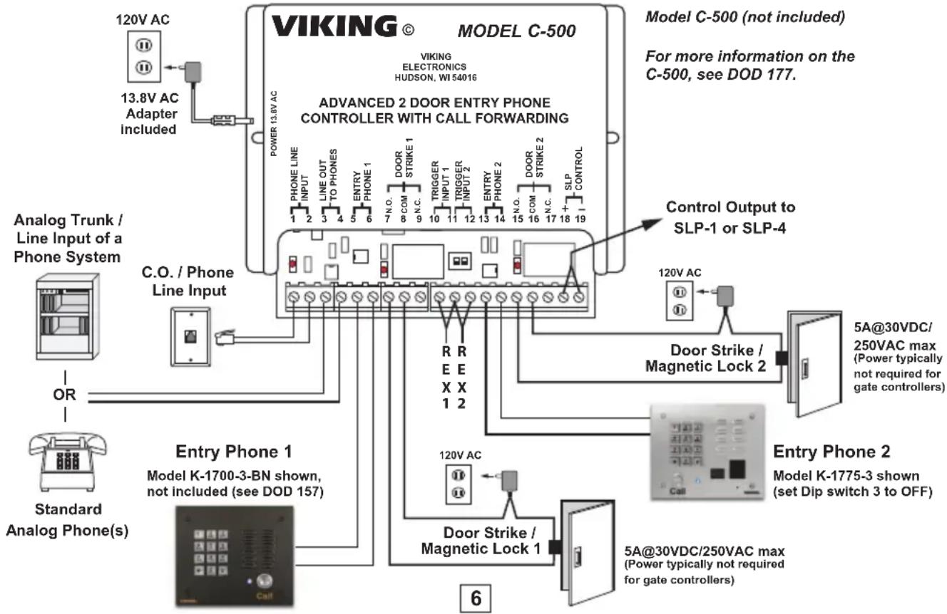
A. C-500 Advanced Two Door/Gate Entry Phone Controller with Call Forwarding
The C-500 allows up to 2 entry phones (expandable to 8 entry phones, see DOD 177) to call into your existing residential or business phones or phone system. Tenants may answer the call, converse with the visitor and activate a contact closure to control electronic gates or door strikes. The C-500 provides user programmable entry phone, "Caller ID," and "Call Waiting" tone when the phone line is in use. The C-500 also has built in five number dialer to call your cell phone or an outside line if there is no answer on the inside phone. If the outside call is busy or ring no answer, the C-500 can call up to four more numbers. Tenants may gain entry at each gate by entering a Touch Tone keyless entry code. Tenants may call out to each entry phone for monitoring purposes. An auxiliary input is also available for connecting a common garage door opener/receiver and auxiliary keyless entry keypads.
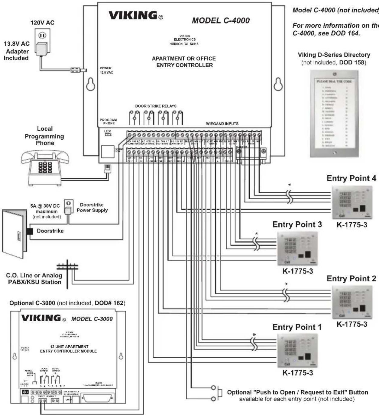
B. Provide 4 Door Entry Points with Keyless Entry (or Optional Card Readers) for up to 250 Apartments or Offices
The C-4000 converts any four Touch Tone phones into multi-number auto dialers that will store up to 250 telephone numbers in non-volatile memory. Use with Viking's K-1775-3 phone to provide vandal resistant handsfree or handset communication from entry points to apartments or offices. When a call initiated by the C-4000 is answered by an apartment or business tenant, a built-in contact closure may be activated to control an electric gate or door strike. Up to 250 entry codes may also be programmed providing tenants with keyless entry or optional 125KHz proximity card readers may be added for proximity card entry. The C-4000 can be programmed locally or remotely using a standard Touch Tone phone. The C-4000 has built-in user dialing restriction to help prevent unauthorized calls and toll fraud.
flowchart
graph TD
    A["120V AC"] --> B["13.8V AC Adapter Included"]
    B --> C["VOKING MODEL C-4000"]
    C --> D["POWER 13.8 VAC"]
    D --> E["APARTMENT OR OFFICE ENTRY CONTROLLER"]
    E --> F["DOOR STRIKE RELAYS"]
    F --> G["WIEGAND INPUTS"]
    G --> H["5A @ 30V DC maximum (not included)"]
    H --> I["Doorstrike Power Supply"]
    I --> J["Doorstrike Phone"]
    J --> K["C.O. Line or Analog PABX/KSU Station"]
    K --> L["VOKING MODEL C-3000"]
    L --> M["POWER 12 UNIT APARTMENT ENTRY CONTROLLER MODULE"]
    M --> N["OUTPUT INPUT 1"]
    N --> O["OUTPUT INPUT 2"]
    O --> P["OUTPUT INPUT 3"]
    P --> Q["OUTPUT INPUT 4"]
    Q --> R["K-1775-3"]
    R --> S["Entry Point 2"]
    S --> T["Entry Point 3"]
    T --> U["Entry Point 4"]
    U --> V["K-1775-3"]
    V --> W["Optional "Push to Open / Request to Exit" Button available for each entry point (not included)"]
    W --> X["Output: Model C-4000 (not included), For more information on the C-4000, see DOD 164."]
    X --> Y["Viking D-Series Directory (not included, DOD 158)."]
    Y --> Z["Please Real The Code"]
If some tenants do not have C.O. phone service, the Viking model C-3000 can be added to ring up to 12 tenant's phones. Up to eight C-3000 units can be cascaded to support a total of 96 "No C.O." tenants.

IMPORTANT: Electronic devices are susceptible to lightning and power station electrical surges from both the AC outlet and the telephone line. It is recommended that a surge protector be installed to protect against such surges.
IF YOU HAVE A PROBLEM WITH A VIKING PRODUCT, CONTACT VIKING TECHNICAL SUPPORT AT: 715-386-8666
Our Technical Support Department is available for assistance Monday to Friday 8:00am - 5:00pm central time. Before you call, please:
- Know the model number, the serial number, and what software version you have (see serial label).
- Have the Product Manual in front of you.
- It is best if you are on site.
RETURNING PRODUCT FOR REPAIR
The following procedure is for equipment that needs repair:
- Customer must contact Viking's Technical Support Department at 715-386-8666 to obtain a Return Authorization (RA) number. The customer MUST have a complete description of the problem, with all pertinent information regarding the defect, such as options set, conditions, symptoms, methods to duplicate problem, frequency of failure, etc.
- Packing: Return equipment in original box or in proper packing so that damage will not occur while in transit. The original product boxes are not designed for shipping - an overpack box is required to prevent damage in transit. Static sensitive equipment such as a circuit board should be in an anti-static bag, sandwiched between foam and individually boxed. All equipment should be wrapped to avoid packing material lodging in or sticking to the equipment. Include ALL parts of the equipment. C.O.D. or freight collect shipments cannot be accepted. Ship cartons prepaid to: VIKING ELECTRONICS
VIKING ELECTRONICS
1531 INDUSTRIAL STREET HUDSON, WI 54016
- Return shipping address: Be sure to include your return shipping address inside the box. We cannot ship to a PO Box.
- RA number on carton: In large printing, write the RA number on the outside of each carton being returned.
RETURNING PRODUCT FOR EXCHANGE
The following procedure is for equipment that has failed out-of-box (within 10 days of purchase):
- Customer must contact Viking's Technical Support at 715-386-8666 to determine possible causes for the problem. The customer MUST be able to step through recommended tests for diagnosis.
- If the Technical Support Product Specialist determines that the equipment is defective based on the customer's input and troubleshooting, a Return Authorization (RA) number will be issued. This number is valid for fourteen (14) calendar days from the date of issue.
- After obtaining the RA number, return the approved equipment to your distributor. Please reference the RA number on the paperwork being shipped back with the unit(s), and also the outside of the shipping box. The original product boxes are not designed for shipping - an overpack box is required to prevent damage in transit. Once your distributor receives the package, they will replace the product over the counter at no charge. The distributor will then return the product to Viking using the same RA number.
- The distributor will NOT exchange this product without first obtaining the RA number from you. If you haven't followed the steps listed in 1, 2 and 3, be aware that you will have to pay a restocking charge.
TWO YEAR LIMITED WARRANTY
Viking warrants its products to be free from defects in the workmanship or materials, under normal use and service, for a period of two years from the date of purchase from any authorized Viking distributor. If at any time during the warranty period, the product is deemed defective or malfunctions, return the product to Viking Electronics, Inc., 1531 Industrial Street, Hudson, WI., 54016. Customer must contact Viking's Technical Support Department at 715-386-8666 to obtain a Return Authorization (RA) number.
This warranty does not cover any damage to the product due to lightning, over voltage, under voltage, accident, misuse, abuse, negligence or any damage caused by use of the product by the purchaser or others. This warranty does not cover non-EWP products that have been exposed to wet or corrosive environments. This warranty does not cover stainless steel surfaces that have not been properly maintained.
NO OTHER WARRANTIES. VIKING MAKES NO WARRANTIES RELATING TO ITS PRODUCTS OTHER THAN AS DESCRIBED ABOVE AND DISCLAIMS ANY EXPRESS OR IMPLIED WARRANTIES OR MERCHANTABILITY OR FITNESS FOR ANY PARTICULAR PURPOSE.
EXCLUSION OF CONSEQUENTIAL DAMAGES. VIKING SHALL NOT, UNDER ANY CIRCUMSTANCES, BE LIABLE TO PURCHASER, OR ANY OTHER PARTY, FOR CONSEQUENTIAL, INCIDENTAL, SPECIAL OR EXEMPLARY DAMAGES ARISING OUT OF OR RELATED TO THE SALE OR USE OF THE PRODUCT SOLD HEREUNDER.
EXCLUSIVE REMEDY AND LIMITATION OF LIABILITY. WHETHER IN AN ACTION BASED ON CONTRACT, TORT (INCLUDING NEGLIGENCE OR STRICT LIABILITY) OR ANY OTHER LEGAL THEORY, ANY LIABILITY OF VIKING SHALL BE LIMITED TO REPAIR OR REPLACEMENT OF THE PRODUCT, OR AT VIKING'S OPTION, REFUND OF THE PURCHASE PRICE AS THE EXCLUSIVE REMEDY AND ANY LIABILITY OF VIKING SHALL BE SO LIMITED.
IT IS EXPRESSLY UNDERSTOOD AND AGREED THAT EACH AND EVERY PROVISION OF THIS AGREEMENT WHICH PROVIDES FOR DISCLAIMER OF WARRANTIES, EXCLUSION OF CONSEQUENTIAL DAMAGES, AND EXCLUSIVE REMEDY AND LIMITATION OF LIABILITY, ARE SEVERABLE FROM ANY OTHER PROVISION AND EACH PROVISION IS A SEPARABLE AND INDEPENDENT ELEMENT OF RISK ALLOCATION AND IS INTENDED TO BE ENFORCED AS SUCH.
FCC REQUIREMENTS
This equipment complies with Part 68 of the FCC rules and the requirements adopted by the ACTA. On the side of this equipment is a label that contains, among other information, a product identifier in the format US:AAAEQ##TXXXX. If requested, this number must be provided to the telephone company.
The REN is used to determine the number of devices that may be connected to a telephone line. Excessive REN's on a telephone line may result in the devices not ringing in response to an incoming call. In most but not all areas, the sum of the REN's should not exceed five (5.0) To be certain of the number of devices that may be connected to a line, as determined by the total REN's, contact the local telephone company. For products approved after July 23, 2001, the REN for this product is part of the product identifier that has the format US:AAAEQ##TXXXX. The digits represented by ## are the REN without a decimal point (e.g., 03 is a REN of 0.3). For earlier products, the REN is separately shown on the label.
The plug used to connect this equipment to the premises wiring and telephone network must comply with the applicable FCC Part 68 rules and requirements adopted by the ACTA. If your home has specially wired alarm equipment connected to the telephone line, ensure the installation of this K-1775-3 does not disable your alarm equipment. If you have questions about what will disable alarm equipment, consult your telephone company or a qualified installer.
If the K-1775-3 causes harm to the telephone network, the telephone company will notify you in advance that temporary discontinuance of service may be required. But if advance notice isn't practical, the telephone company will notify the customer as soon as possible. Also, you will be advised of your right to file a complaint with the FCC if you believe it is necessary.
The telephone company may make changes in its facilities, equipment, operations, or procedures that could affect the operation of the equipment. If this happens, the telephone company will provide advance notice in order for you to make the necessary modifications to maintain uninterrupted service.
If trouble is experienced with the K-1775-3 for repair or warranty information, please contact:
Viking Electronics, Inc., 1531 Industrial Street, Hudson, WI 54016 Phone: (715) 386-8666
If the equipment is causing harm to the telephone network, the telephone company may request that you disconnect the equipment until the problem is resolved.
Connection to Party Line Service is subject to State Tariffs. Contact the state public utility commission, public service commission or corporation commission for information.
WHEN PROGRAMMING EMERGENCY NUMBERS AND (OR) MAKING TEST CALLS TO EMERGENCY NUMBERS:
Remain on the line and briefly explain to the dispatcher the reason for the call. Perform such activities in the off-peak hours, such as early morning or late evenings.
It is recommended that the customer install an AC surge arrester in the AC outlet to which this device is connected. This is to avoid damaging the equipment caused by local lightning strikes and other electrical surges.
PART 15 LIMITATIONS
This equipment has been tested and found to comply with the limits for a Class A digital device, pursuant to Part 15 of the FCC Rules. These limits are designed to provide reasonable protection against harmful interference when the equipment is operated in a commercial environment. This equipment generates, uses, and can radiate radio frequency energy and, if not installed and used in accordance with the instruction manual, may cause harmful interference to radio communications. Operation of this equipment in a residential area is likely to cause harmful interference in which case the user will be required to correct the interference at his own expense.
Due to the dynamic nature of the product design, the information contained in this document is subject to change without notice. Viking Electronics, and its affiliates and/or subsidiaries assume no responsibility for errors and omissions contained in this information. Revisions of this document or new editions of it may be issued to incorporate such changes.
- Vandal Resistant Entry Phones with Built-In Keypad, Proximity Card Reader, and Color Video Camera
- Features
- Applications
- Specifications
- ENTRY PHONE SPECIFICATIONS
- CAMERA SPECIFICATIONS
- PROXIMITY CARD SPECIFICATIONS
- Features Overview
- Condensation Drain Hole
- Mounting
- Wiring the K-1775-3
- Camera Wiring and Adjustments
- Using a Video Encoder to Convert the Analog NTSC Video to IP
- Adjusting the Camera
- Programming
- DIP Switches
- Volume Adjustments
- Microphone
- Speaker
- Auto-Answer Feature (DIP Switch 7)
- Push Button Hang Up (DIP Switch 8)
- VOX (Talk/Listen) Switching Speed (DIP Switch 4)
- Advanced Call Progress Detection
- Operation
- C-500 Advanced Two Door/Gate Entry Phone Controller with Call Forwarding
- Provide 4 Door Entry Points with Keyless Entry (or Optional Card Readers) for up to 250 Apartments or Offices
- IF YOU HAVE A PROBLEM WITH A VIKING PRODUCT, CONTACT VIKING TECHNICAL SUPPORT AT: 715-386-8666
- RETURNING PRODUCT FOR REPAIR
- RETURNING PRODUCT FOR EXCHANGE
- TWO YEAR LIMITED WARRANTY
- FCC REQUIREMENTS
- PART 15 LIMITATIONS
Brand : VIKING
Model : K-1775-3-EWP
Category : Access Control System