K-1275-IP-EWP - Access Control System VIKING - Free user manual and instructions
Find the device manual for free K-1275-IP-EWP VIKING in PDF.

User questions about K-1275-IP-EWP VIKING
0 question about this device. Answer the ones you know or ask your own.
Ask a new question about this device
Download the instructions for your Access Control System in PDF format for free! Find your manual K-1275-IP-EWP - VIKING and take your electronic device back in hand. On this page are published all the documents necessary for the use of your device. K-1275-IP-EWP by VIKING.
USER MANUAL K-1275-IP-EWP VIKING
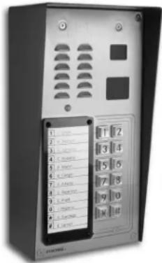
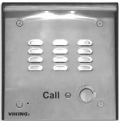
Vandal Resistant VoIP Entry Phone System with Built-In Directory, Proximity Card Reader, 12 Button Auto Dialer, and Analog Video Camera
The K-1275-IP is a durable and attractive handsfree phone for apartment and residential door entry applications requiring a vandal resistant VoIP speaker phone with an integrated 125 KHz Proximity Card Reader and analog Color Video Camera. The K-1275-IP phone is designed to provide quick and reliable handsfree communication for SIP VoIP phone systems or cloud based service providers. The unit can be programmed from any PC on the same LAN or remotely using a Static IP Address. The K-1275-IP entry phone can dial up to 12 programmable numbers and 12 rollover numbers. The brushed stainless steel faceplate has a built-in 12 resident directory with a waterproof, scratch resistant lens and 12 buttons for single push auto-dialing of a tenant's phone number or business extension.
When the K-1275-IP phone is connected to an apartment or business tenant, a built-in contact closure may be activated to control an electric gate or door strike. Up to 1,000 keyless entry codes may be programmed, providing tenants with keyless entry. The K-1275-IP has a built-in Proximity Card Reader with capacity to program up to 1,000 card numbers. Keyless entry codes and card numbers can be programmed to only allow access at specific times and/or day of the week. The K-1275-IP includes a request for exit (REX) input and also offers event logging with time and date stamp.
The K-1275-IP-EWP shares all of the features of the K-1275-IP in addition to Enhanced Weather Protection (EWP) for outdoor installations where the unit is exposed to precipitation or condensation. EWP products are designed to meet IP66 standards and may feature foam rubber gaskets, sealed connections, gel-filled butt connectors, as well as potted circuit boards. For more information on EWP, see DOD 859.

text_image
1. Start 2. Startout 3. Volumes 4. Racks 5. Marks 6. Linger 7. Scales 8. Pines 9. Highers 10. Average 11. Average 12. 13 14. 15 16. 16 17. 17 18. 18 19. 19 20. 20 21. 21 22. 22 23. 23 24. 24 25. 25 26. 26 27. 27 28. 28 29. 29 30. 30 31. 31 32. 32 33. 33 34. 34 35. 35 36. 36 37. 37 38. 38 39. 39 40. 40 41. 41 42. 42 43. 43 44. 44 45. 45 46. 46 47. 47 48. 48 49. 49 50. 50 51. 51 52. 52 53. 53 54. 54 55. 55 56. 56 57. 57 58. 58 59. 59 60. 60 61. 61 62. 62 63. 63 64. 64 65. 65 66. 66 67. 67 68. 68 69. 69 70. 70 71. 71 72. 72 73. 73 74. 74 75. 75 76. 76 77. 77 78. 78 79. 79 80. 80 81. 81 82. 82 83. 83 84. 84 85. 85 86. 86 87. 87 88. 88 89. 89 90. 90 91. 91 92. 92 93. 93 94. 94 95. 95 96. 96 97. 97 98. 98 99. 99K-1275-IP
"Brushed 316 Stainless Steel" (similar to brushed nickel)
text_image
1. Phone 2. Phone 3. Phone 4. Phone 5. Phone 6. Phone 7. Phone 8. Phone 9. Phone 10. Phone 11. Phone 12. Phone 13. Phone 14. Phone 15. Phone 16. Phone 17. Phone 18. Phone 19. Phone 20. Phone 21. Phone 22. Phone 23. Phone 24. Phone 25. Phone 26. Phone 27. Phone 28. Phone 29. Phone 30. Phone 31. Phone 32. Phone 33. Phone 34. Phone 35. Phone 36. Phone 37. Phone 38. Phone 39. Phone 40. Phone 41. Phone 42. Phone 43. Phone 44. Phone 45. Phone 46. Phone 47. Phone 48. Phone 49. Phone 50. Phone 51. Phone 52. Phone 53. Phone 54. Phone 55. Phone 56. Phone 57. Phone 58. Phone 59. Phone 60. PhoneK-1275-IP
(shown in optional VE-5x10-SS surface mount box)

Installation requires the assistance of a Network Administrator / IT Technician.
Features
- Vandal Resistant Features: 14 gauge louvered 316 stainless steel faceplate with permanent laser etched graphics. Speaker/mic screen. Heavy duty metal keypad buttons and T-10 Security Torx drive mounting screws.
- Weather Resistant Features: Marine grade 316 stainless steel faceplate and screws. Keypad internally sealed per IP67. Mylar speaker. Self-draining mic mount. Faceplate, mic and speaker gaskets.
- Built-in high resolution analog NTSC color video camera with wide viewing angle, tilt/swivel adjustments and wide operating temperature: -40°F to 140°F
• Built-in 125KHz 26-bit Wiegand proximity card reader with LED and beep card read confirmation and EWP board protection - Two sets of SPDT 2 Amp relay contacts for door/gate or camera control
- Optional RC-4A for Secure Remote Relay Control, see DOD 582
- Blue "Call /Status" LED indicator
- SIP compliant (see page 2 for compatible SIP servers and IP phone systems)
- Outbound Proxy, Authentication ID, Peer to Peer, VLAN Tagging
• PoE powered (class 2, <6.5 Watts)
• Automatic Noise Canceling (ANC) feature for operation in noisy environments - Viking's proprietary VOX switching eliminates the need for "Push to Talk" mode
• Network downloadable firmware
Applications
• Residential Gate Entrance
• Courtesy Assistance Phone
- Customer Service Phone
• Automated Teller (ATM) Phone
- Use with LRR-4 Long Range RFID Transmitter DOD 226
- Use with any of Viking's Proximity Credentials: PRX-C, PRX-C-ISO, PRX-FOB, and LRT-4 see DOD 198 and 226
Information: 715-386-8861 www.VikingElectronics.com
- Programmable to speed dial up to 12 numbers
• Cycles to rollover phone number on busy or no-answer - Program up to 1,000 keyless entry codes and/or proximity card numbers
- Keyless entry codes and proximity card numbers can be programmed to only allow access at specific times and days of week
• Event logging with time and date stamp - Optional Enhanced Weather Protection (EWP), EWP products are designed to meet IP66 Ingress Protection Rating, see DOD 859
- Hangs up on busy signal, time-out or touch tone command
- Remotely programmable
- Extended temperature range -40^ to 140^
- Programmable volume adjustments for microphone and speaker
- Selectable auto-answer feature for monitoring
- Flush mount with included Zinc plated steel rough-in box,
- Surface mount using an optional VE-5x10 surface mount box (not included, see DOD 424)
- Optional LRR-4 Long Range RFID receiver, see DOD 226
- Optional VE-LIGHT kit to illuminate the front panel at night, see DOD 428
• Diagnostics for testing mic, speaker, relays, and proximity cards
Specifications
Power: PoE class 2 (<6.5 Watts)
Dimensions: Overall: 5" x 10" x 2.5" (127 mm x 254 mm x 63.5 mm)
Rough-in box: 4.5" x 9.12" x 2.5" (114 mm x 232 mm x 64 mm)
Shipping Weight: K-1275-IP: 4.4 lbs (2.0 kg), K-1275-IP-EWP: 4.6 lbs (2.09 kg)
Operating Temperature: -30°F to 140°F (-34°C to 60°C)
Humidity - Standard Products: 5% to 95% non-condensing
Humidity - EWP Products: Up to 100%
Audio Codecs: G711u, G711a, G722
Network Compliance: IEEE 802.3 af PoE, SIP 2.0 RFC3261, 100BASE-TX with auto cross over
Regulatory Compliance: CE, FCC Part 15 and Canada ICES-003 Class A
Connections: (1) RJ45 10/100 Base-T, (12) gel-filled butt connectors
VoIP SIP System Compatibility
For compatibility and vendor specific detailed configuration instructions, see the Viking VoIP SIP System Compatibility List, DOD 944. To open and download this PDF file:
Scan the QR code below to open and download the Viking VoIP SIP System Compatibility List
- OR -

-
Go to www.vikingelectronics.com and enter 944 in the search box
-
Click Application Note (DOD 944) to open and download the PDF
Important: Exclusion from this list means only that compatibility has not been verified, it does not mean incompatibility. If you have questions, please call Viking Electronics at 715-386-8861.
Camera Specifications
Image Sensor: 1/4" color CMOS
Video Output: 1 VP-P composite, NTSC, 75 ohms
Resolution: 420 lines (640 x 480 @ 30fps / 307,200 pixels)
Sensitivity: 0.025 LUX (50 IRE) F 1.2 3200K
Lens: 2.1mm, conical pinhole
FOV (Field of View): 80° Horizontal, 60° Vertical, 100° Diagonal
Tilt/Swivel Adjustment: Vertical +/- 20°, horizontal +/- 30° (see Diagram A)
IR Compatibility: This camera is equipped with an OLP (Optical Low Pass) filter to maintain correct video color in outside applications. The standard camera is NOT compatible with IR illuminators. If IR illumination is required, you will need to replace the existing camera with a Viking model VCAM-1IR. For more information, see DOD# 190.
Maximum Wire Run Length: 1000 ft with *RG59/RG6 for video and CAT5 for power (1 pair) and entry phone audio (1 pair). 150 ft with CAT5E for video, power and entry phone audio (longer video runs are possible by using video balun transceivers.
* Note: RG59 or RG6 with solid center conductor and 95% bare copper braid shield.
Diagram A
Camera Horizontal Field of View:

text_image
80° Lens FOV Rotate Left 30° Rotate Right 30° Camera LensProximity Card Reader Specifications
Power: PoE powered from K-1275-IP PCB
Maximum Cable Length: 500 ft 24 Awg stranded shielded (Belden 9537)
Frequency: 125KHz
Format: 26 bit Wiegand
Read Range: 1.25" to 2.0"
Technologies Supported: Viking PRX-C, PRX-C-ISO, PRX-FOB, LRT-4, certain legacy
HID® proximity protocols* and certain AWID 125Khz proximity protocols**
Transducer: Beeps during card read
LED: Red, turns off during card read
Humidity: Up to 100% (fully potted EWP)
Operating Temperature: -34^ C to 65^ C ( -30^ F to 150^ F)
* HID and the HID logo are registered trademarks of HID Global Corporation, an ASSA
ABLOY company. All other trademarks are the property of their respective owners.
** AWID is a trademark of Applied Wireless Identification Group.
Definitions
Client: A computer or device that makes use of a server. As an example, the client might request a particular file from the server.
DHCP: Dynamic Host Configuration Protocol. In this procedure the network server or router takes note of a client's MAC address and assigns an IP address to allow the client to communicate with other devices on the network.
DNS Server: A DNS (Domain Name System) server translates domain names (ie: www.vikingelectronics.com) into an IP address.
Ethernet: Ethernet is the most commonly used LAN technology. An Ethernet Local Area Network typically uses twisted pair wires to achieve transmission speeds up to 1Gbps.
Host: A computer or device connected to a network.
Host Name: A host name is a label assigned to a device connected to a computer network that is used to identify the device in various forms of network communication.
Hosts File: A file stored in a computer that lists host names and their corresponding IP addresses with the purpose of mapping addresses to hosts or vice versa.
Internet: A worldwide system of computer networks running on IP protocol which can be accessed by individual computers or networks.
IP: Internet Protocol is the set of communications conventions that govern the way computers communicate on networks and on the Internet.
IP Address: This is the address that uniquely identifies a host on a network.
LAN: Local Area Network. A LAN is a network connecting computers and other devices within an office or building.
Lease: The amount of time a DHCP server reserves an address it has assigned. If the address isn't used by the host for a period of time, the lease can expire and the address can be assigned to another host.
MAC Address: MAC stands for Media Access Control. A MAC address, also called a hardware address or physical address, is a unique address assigned to a device at the factory. It resides in the device's memory and is used by routers to send network traffic to the correct IP address. You can find the MAC address of your K-1275-IP phone printed on a white label on the top surface of the PoE LAN port.
Router: A device that forwards data from one network to another. In order to send information to the right location, routers look at IP Address, MAC Address and Subnet Mask.
RTP: Real-Time Transport Protocol is an Internet protocol standard that specifies a way for programs to manage the real-time transmission of multimedia data over either unicast or multicast network services.
Server: A computer or device that fulfills requests from a client. This could involve the server sending a particular file requested by the client.
Session Initiation Protocol (SIP): Is a signaling communications protocol, widely used for controlling multimedia communication sessions such as voice and video calls over Internet Protocol (IP) networks. The protocol defines the messages that are sent between endpoints, which govern establishment, termination and other essential elements of a call.
Static IP Address: A static IP Address has been assigned manually and is permanent until it is manually removed. It is not subject to the Lease limitations of a Dynamic IP Address assigned by the DHCP Server. The default static IP Address is: 192.168.154.1
Subnet: A portion of a network that shares a common address component. On TCP/IP networks, subnets are defined as all devices whose IP addresses have the same prefix. For example, all devices with IP addresses that start with 100.100.100. would be part of the same subnet. Dividing a network into subnets is useful for both security and performance reasons. IP networks are divided using a subnet mask.
TCP/IP: Transmission Control Protocol/Internet Protocol is the suite of communications protocols used to connect hosts on the Internet. TCP/IP uses several protocols, the two main ones being TCP and IP. TCP/IP is built into the UNIX operating system and is used by the Internet, making it the de facto standard for transmitting data over networks.
TISP: Telephone Internet Service Provider
WAN: Wide Area Network. A WAN is a network comprising a large geographical area like a state or country. The largest WAN is the Internet.
Wireless Access Point (AP): A device that allows wireless devices to connect to a wired network using Wi-Fi, or related standards. The AP usually connects to a router (via a wired network) as a standalone device, but it can also be an integral component of the router itself.
Wireless Repeater (Wireless Range Extender): takes an existing signal from a wireless router or access point and rebroadcasts it to create a second network. When two or more hosts have to be connected with one another over the IEEE 802.11 protocol and the distance is too long for a direct connection to be established, a wireless repeater is used to bridge the gap.
Features Overview

text_image
Mounting Screws: (4) 6-32 X 3/4" Marine grade 316 stainless steel, flat head, T-10 Torx security screws and drive bit (included). Speaker Screen: Speaker screen with 0.018" wide slots to prevent punctures from paperclips, etc. Speaker: Mylar speaker with rubber gasket to maintain water-tight seal and eliminate water deterioration. Microphone: Omni-directional microphone with protective water-resistant cloth. Blue Call LED: Lights steady when idle, flashes during dialing, then lights steady when answered. Faceplate Material: 14 gauge 316 stainless steel with #4 brushed finish. Laser Etched Graphics: For long lasting easy to read graphics. Front View of the K-1275-IP Entry Phone Protective Camera Window: Impact resistant polycarbonate lens with scratch resistant coating and water-tight gasket. Color Video Camera: Wide operating temperature range of -40°F to 140°F, NTSC composite video output with 420 lines of resolution, 80° wide viewing angle lens, tilt and swivel adjustments for aiming towards visitors. Proximity Card Reader: 26-bit Wiegand, 125KHz, red LED turns off and transducer will beep during card read. Fully potted EWP. Read range 1.25" to 2.0". Impact resistant polycarbonate lens with water-tight gasket. Keypad: Push to initiate call, push again to disconnect. Zinc Die cast with Satin Chrome Finish, internally sealed per IP67. Condensation Drain Hole Viking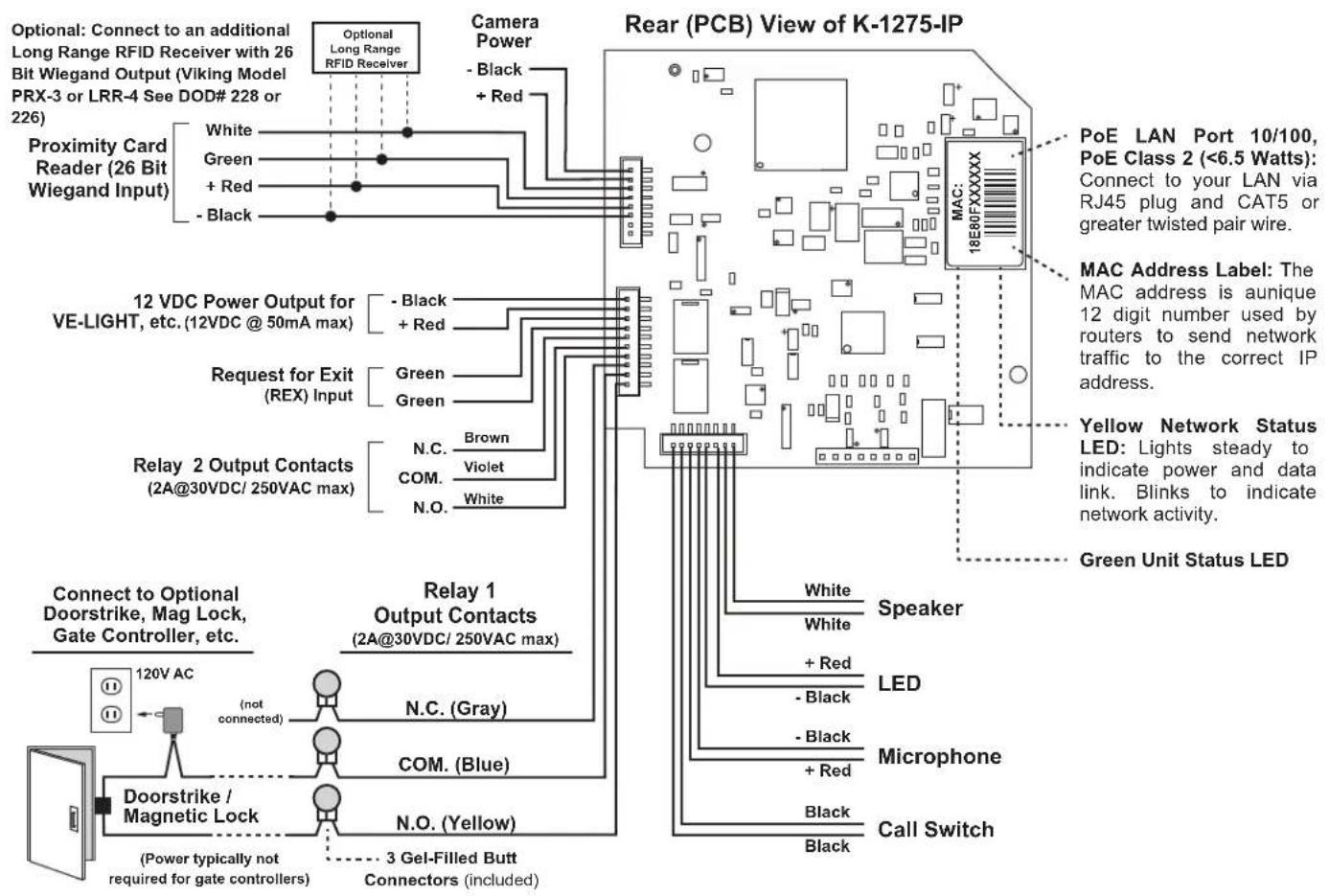
flowchart
graph TD
    A["Optional: Connect to an additional Long Range RFID Receiver with 26 Bit Wiegand Output (Viking Model PRX-3 or LRR-4 See DOD# 228 or 226)"] --> B["Proximity Card Reader (26 Bit Wiegand Input)"]
    B --> C["White"]
    B --> D["Green"]
    B --> E["+ Red"]
    B --> F["- Black"]
    C --> G["Camera Power"]
    D --> G
    E --> G
    F --> G
    G --> H["12 VDC Power Output for VE-LIGHT, etc. (12VDC @ 50mA max)"]
    H --> I["Black + Red"]
    H --> J["Green"]
    H --> K["Green"]
    H --> L["N.C. Brown"]
    H --> M["COM. Violet"]
    H --> N["N.O. White"]
    I --> O["Relay 1 Output Contacts (2A@30VDC/250VAC max)"]
    J --> O
    K --> O
    L --> O
    M --> O
    N --> O
    O --> P["Relay 2 Output Contacts (2A@30VDC/250VAC max)"]
    P --> Q["120V AC"]
    P --> R["Doorstrike / Magnetic Lock"]
    R --> S["(not connected)"]
    R --> T["N.C. (Gray)"]
    R --> U["COM. (Blue)"]
    R --> V["N.O. (Yellow)"]
    R --> W["3 Gel-Filled Butt Connectors (included)"]
    style A fill:#f9f,stroke:#333
    style B fill:#ccf,stroke:#333
    style C fill:#cfc,stroke:#333
    style D fill:#fcc,stroke:#333
    style E fill:#cff,stroke:#333
    style F fill:#ffc,stroke:#333
    style G fill:#fcf,stroke:#333
    style H fill:#cff,stroke:#333
    style I fill:#ffc,stroke:#333
    style J fill:#cfc,stroke:#333
    style K fill:#fcc,stroke:#333
    style L fill:#ffc,stroke:#333
    style M fill:#cfc,stroke:#333
    style N fill:#fcc,stroke:#333
    style O fill:#ffc,stroke:#333
    style P fill:#cfc,stroke:#333
    style Q fill:#fcc,stroke:#333
    style R fill:#cfc,stroke:#333
    style S fill:#fcc,stroke:#333
    style T fill:#cfc,stroke:#333
Note: The gel-filled (water-tight) butt connectors are designed for insulation displacement on 19-26 gauge wire with a maximum insulation of 0.082 inches.
Installation and Mounting
A. Mounting
The K-1275-IP is designed to be installed in a sheltered location, and is not meant to be used outdoors. For outdoor applications use the K-1275-IP-EWP. The K-1275-IP can either be installed as a flush mount unit using the included rough in box, or as a surface mount unit using an optional VE-5x10 or VE-5x10-SS. The rough in box uses the inner set of four holes on the face plate while the VE-5x10 uses the outside set of holes. A set of dummy screws and nuts are provided to fill the unused mounting holes.
Note: Write down the MAC Address (found on the RJ-45 jack) as this may be needed to identify the unit after installation.

B. Changing the Directory
To install a directory, remove the four screws that mount the directory lens to the front of the K-1275-IP using the included Allen wrench. Insert a paper directory behind the lens and secure the two back onto the front panel being careful to align the names with the front panel graphics.
Note: To print directory forms for the K-1275-IP, go to www.vikingelectronics.com and enter "930" in the DOD field at the top of the page for a direct link to the PDF.

flowchart
graph LR
    A["Screw"] --> B["Document"]
    C["Paper Directory"] -.-> D["Directory Lens"]
    B --> E["Server with Panel"]
    D --> E
IMPORTANT: Electronic devices are susceptible to lightning and power station electrical surges from the AC outlet. It is recommended that a surge protector be installed to protect against such surges.
A. Using RG59 for Analog Video (Recommended)
| Back View of the K-1275-IP | 3-Wire Gel-Filled Butt Connectors included (3M Scotchlok UR2) | * Note: RG59 or RG6 with solid center conductor and 95% bare copper braid shield. | ||||
| Center conductor stripped back 5/8" | * RG59 or RG6 Shielded Video Cable, up to 1000 ft | "F" Connector | "F" to Phono Plug Adapter (Radio Shack part #278-252) | To unused input on TV, VHF modulator, whole house video distribution equipment, IP video encoder (Axis M7011), etc. | ||
| Yellow (Video) | ||||||
| Twisted foil and braided shield | ||||||
| Yellow/Red | OR | |||||
| - Black (GND) | Black | ** Note: For ease of installation, a Viking Female "F" to Wire Converter Cable can be used (Part # 261217) or "BNC" to wire converter cable (Part # U213510) can be used. Go to www.vikingelectronics.com and click on "Spare Parts" to order. | ||||
| ** Female "F" to Wire or "BNC" to Wire Converter Cable (not included) | ||||||
B. Using CAT5E or CAT6 for Analog Video (see Caution below)
| Back View of the K-1275-IP | To unused input on TV, VHF modulator, whole house video distribution equipment, IP video encoder (Axis M7011), etc. | ||||
| 3-Wire Gel-Filled Butt Connectors included (3M Scotchlok UR2) | Video Out (+) | (-) | |||
| Video GND (-) | (+) | ||||
| W/G | Green | Phono (RCA) Plug, F Connector, Etc. | |||
| Video Out (+) w/g | CAT5E or CAT6 Cable (see Caution below) | ||||
| Video GND (-) Green | |||||
| * Up to 150 ft | |||||
* Note: Up to 150 ft video cable run length can be achieved using CAT5E or CAT6 cable. Longer cable runs can be used if a passive or active video Balun transceiver is used on each end of the cable. Generally, passive transceivers can achieve up to 750 ft cable runs where active transceivers can achieve up to 3000 ft runs depending on cable type, etc. The type of video balun transceiver required is specific to your cable run length. For more information on video balun transceivers go to: www.northernvideo.com.
Caution: When routing CAT5E or CAT6 cable, maintain a minimum distance of 3 ft from any parallel high voltage wire (110 VAC) and a minimum of 2 ft from crossing any high voltage wire. For installations where RF noise is expected (commercial applications) or wire runs are near high voltage (110 VAC) wires, a shielded video cable such as RG6 is recommended.
C. Using a Video Encoder to Convert the Analog NTSC Video to IP
Axis manufactures video servers that encode analog video signal for transmission across IP network or the internet. The single channel model M7011 is shown. Supplied software allows you to access Axis units connected to the network (auto-discovery) and program them via a web page interface. The video can then be monitored from any location on the network.
For more information, go to www.axis.com
Axis Model M7011 shown
D. Adjusting the Camera
The camera can be tilted and rotated to your desired position. A portable service (test) monitor can be used to determine the correct viewing angle during installation.
Important: To prevent the edge of the faceplate from being viewed in the video image, do not rotate the camera beyond 30 degrees or tilt beyond 20 degrees.
Vertical (Tilt) Adjustment +/- 20 degrees maximum
Horizontal (Rotation) Adjustment +/- 30 degrees maximum
1 2 3 4 5 8 7 9 9 0 ★ #
Typical Installation on SIP Based VoIP Phone System

flowchart
graph TD
    A["Viking K-1275-IP Entry Phone"] -->|100m (328 ft) maximum*| B["SIP VoIP PBX or PC with SIP Server Software"]
    B --> C["Internet"]
    D["Viking supplies"] -->|Customer's Responsibility| E["Optional PoE Injector\n(If VoIP PBX does not have PoE)"]
    E --> F["Optional Switch / Hub"]
    F --> G["VIKING MODEL RC-4A NETWORK ENABLED RELAY CONTROLLER"]
    G --> H["Optional Viking model RC-4A Secure Remote Relay Controller, see page 7 (DOD 582)"]
    style A fill:#f9f,stroke:#333
    style B fill:#ccf,stroke:#333
    style C fill:#cfc,stroke:#333
    style D fill:#fcc,stroke:#333
    style E fill:#cff,stroke:#333
    style F fill:#ffc,stroke:#333
    style G fill:#fcc,stroke:#333
    style H fill:#fff,stroke:#333
* Note: A PoE extender can be used for an additional 100 meters per extender. For longer runs (up to 2 km / 1.2 miles) a ethernet to fiber media converter can be used.
PC Requirements
- IBM compatible personal computer with: Windows 7, 8 or 10
- Adobe Acrobat Reader 8 or higher
• K-1275-IP hardware
• Available LAN with PoE (class 2, <6.5 watts)
- Ethernet cable (CAT5 minimum)
- 1 MB minimum free hard drive space for installation
• 16MB of free physical RAM
PC Programming
Download and install the programming software
- Go to www.vikingelectronics.com and enter K-1275-IP in the search box
- Click K-1275-IP in the search results
- Scroll down the page to Downloads, click IP Programming Software
- Install the programming software by saving or opening the file and then clicking on setup Viking IP Programming.exe
- Follow the prompts on your screen to complete software installation.
- To start the Viking IP Programming application, click on the Viking IP Programming icon on your desk top. The Main screen will appear, allowing the user to program any K-1275-IP Series connected to that LAN.
Note: PC must be connected to the same LAN as the K-1275-IP Series.
A. Manually Muting SIP/Network Failure Alarm Beeps (3 beeps repeated every 30 seconds)
With the unit connected and powered (Green LED on and Yellow LED off or blinking) it will output 3 beeps every 30 seconds and turn the call LED on and off once per second to indicate a SIP registration failure, failure to receive an echo reply from pinged gateway or Ethernet connection failure. You can manually disable the beeps by pressing and holding the “*” button for 5 seconds (2 beeps will then be heard) or by clicking the “Mute Alarm Until Next Failure” button in the Viking VoIP programming software. The LED will continue to flash allowing you to trouble shoot the failure.
B. Connect / Disconnect
Open the "Viking IP Programming" software on the PC and the start screen shown below will appear. Any Viking IP phones that are connected to the network will appear on the list. Simply select the K-1275-IP Series on the list and click on the "Connect" button at the bottom or double click the selected phone. If the security code of the selected phone is still set to default (845464), the PC software will not require entering a security code to connect to the phone. K-1275-IP Series have a default name of "VIKING_MK64_Vik02", so if many phones are connected to the same network that all have the default name, MAC addresses must be used to identify each phone.
When finished programming, click on the "Disconnect" button at the bottom. Closing the program will also automatically disconnect the unit.
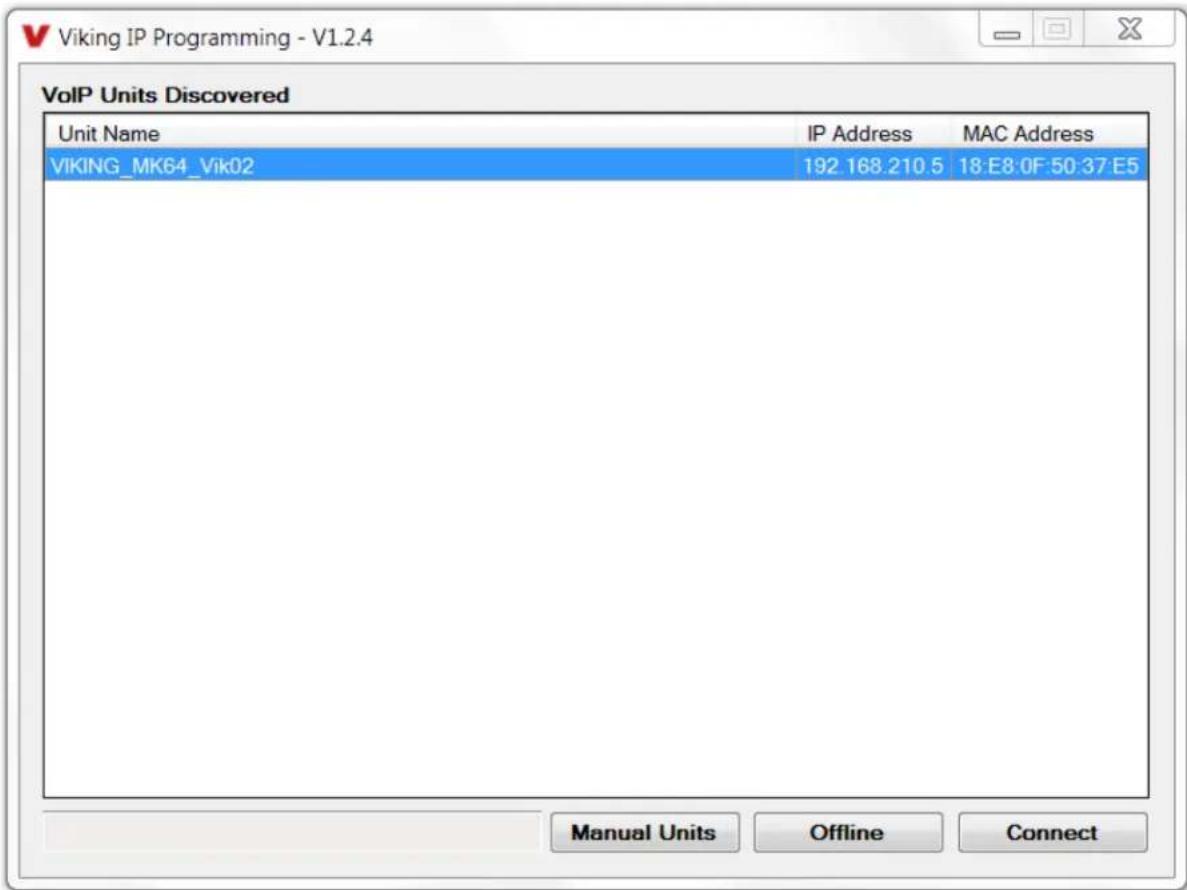
text_image
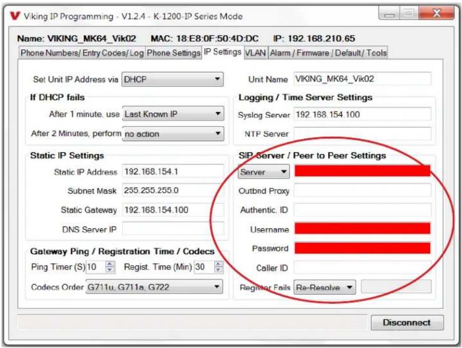
Viking IP Programming - V1.2.4 VolP Units Discovered Unit Name IP Address MAC Address VIKING_MK64_Vik02 192.168.210.5 18:E8:0F 50:37:E5 Manual Units Offline ConnectC. Configuring the K-1275-IP Network Settings
| Step 1. | Open the “Viking IP Programming” software on a windows PC that is connected to the same LAN as the K-1275-IP Series phone to be programmed. |
| Step 2. | The window in the upper left corner of the menu will show you each K-1275-IP Series phone that is connected to that LAN. Select the unit with the same MAC address shown on the label located on the top of the Ethernet connector on the K-1275-IP Series phone. |
| Step 3. | Click the “Connect” button. If a pop up window appears, enter the unit’s security code (factory set to 845464) then click “OK”. |
| Step 4. | The program will then read and display the K-1275-IP Series phone’s IP and programming settings. |
| Step 5. | Click on the “IP Settings” tab. |
| Step 6. | Select the appropriate value Static IP Settings or DHCP for “Set Unit IP Address via”. Note: changing the IP address will cause you to have to reconnect to the unit. Enter the values for the fields in “if DHCP fails” or “Static IP Settings” as needed. |
| Step 7. | Set the “Unit Name”, “Logging / Time Server Settings” as needed. |
| Step 8. | Select Peer-Peer in the “SIP Server / Peer to Peer Settings” to use the unit in Peer to Peer mode. Select Server to register with a SIP registrar server and fill in the “Outbnd Proxy” (SIP Outbound Proxy Server Address, “ip:port”), “Authentic. ID” (SIP Authentication ID), “Username” (SIP Username,), “Password” (SIP Password), and “Caller ID” (SIP Caller ID) with values from your VoIP provider. |
text_image
Viking IP Programming - V1.2.4 - K-1200-IP Series Mode Name: VIKING_MK64_Vik02 MAC: 18:E8:0F:50:4D:DC IP: 192.168.210.65 Phone Numbers/Entry Codes/Log Phone Settings IP Settings VLAN Alarm / Firmware / Default / Tools Set Unit IP Address via DHCP Unit Name VIKING_MK64_Vik02 If DHCP fails After 1 minute. use Last Known IP After 2 Minutes, perform no action Logging / Time Server Settings Syslog Server 192.168.154.100 NTP Server Static IP Settings Static IP Address 192.168.154.1 Subnet Mask 255.255.255.0 Static Gateway 192.168.154.100 DNS Server IP SIP Server / Peer to Peer Settings Server Outbind Proxy Authentic. ID Username Password Caller ID Gateway Ping / Registration Time / Codecs Ping Timer (S) 10 Regist. Time (Min) 30 Codecs Order G711u, G711a, G722 Register Fails Re-Resolve DisconnectExample 1: On-Premise SIP Phone System
Example 2: Cloud Based Service Provider
(Voip.ms)
Example 3: Cloud Based Service Provider requiring Outbound Proxy and Authentication ID (RingCentral)
(Panasonic TDE 100/200)

text_image
SIP Server / Peer to Peer Settings Server 192.168.0.101 Outbnd Proxy Authentic. ID Username 117 Password 9140 Caller ID Door 1 Register Fails Re-Resolve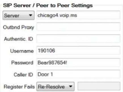
text_image
SIP Server / Peer to Peer Settings Server ▼ chicago4.voip.ms Outbnd Proxy Authentic. ID Username 190106 Password Bear987654! Caller ID Door 1 Register Fails Re-Resolve ▼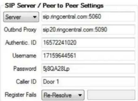
text_image
SIP Server / Peer to Peer Settings Server ▼ sip.ringcentral.com:5060 Outbnd Proxy sip20.ringcentral.com:5090 Authentic. ID 16572241020 Username 17159644561 Password 5j8QA28Lp Caller ID Door 1 Register Fails Re-Resolve ▼D. Configuring K-1275-IP VLAN Settings
| Step 1. Click on the “VLAN” tab |
| Step 2. Disable or enable VLAN tagging by setting the value of “VLAN Tagging”. |
| Step 3. Set the VLAN tag ID by selecting an integer (1 to 4094) in “ID for all packets”. |
| Step 4. Set the Priority Code Point (PCP) value for all not SIP and RTP packets in the “PCP for all packets” input (0 is default, priorities are from low to high: 0, 1, 2, 3, 4, 5, 6, 7). Set the “PCP for SIP packets” (3 is default). Set the “PCP for RTP packets” (5 is default). |

text_image
Viking IP Programming - V1.2.4 - K-1200-IP Series Mode Name: VIKING_MK64_Vik02 MAC: 18:E8:0F:50:4D:DC IP: 192.168.210.65 Phone Numbers/Entry Codes/Log Phone Settings IP Settings VLAN Alarm / Firmware / Default / Tools VLAN Tagging Please exercise caution when setting VLAN tags, as an incorrect setting can disable the ability to connect to the unit until it is manually reset to VLAN Tagging Disabled ID for all packets 0 PCP for all packets 0 PCP for SIP packets 3 PCP for RTP packets 5 DisconnectE. Manually Resetting the Security Code to Enter Programming
| Step 1. | Power down the K-1275-IP phone by disconnecting the LAN Cable (RJ45 plug). |
| Step 2. | Press and hold the # key on keypad, then reconnect the LAN Cable (RJ45 plug). |
| Step 3. | Continue to hold # key until you hear 2 beeps, (approximately 6 seconds). Then release the button. The “Call” LED will remain off for the first 3 seconds, flash slowly for 3 seconds then fast flash (after 2 beeps), indicating when to release button. |
| Step 4. | The security code is now reset to 845464 (factory default). |
| Step 5. | You can now enter programming by following the steps in section B. |
F. Manually Resetting All Network Parameters to Factory Default
| Step 1. | Power down the K-1275-IP phone by disconnecting the LAN Cable (RJ45 plug). |
| Step 2. | Press and hold the # key on keypad, then reconnect the LAN Cable (RJ45 plug). |
| Step 3. | Continue to hold # key until you hear 2 beeps, (approximately 6 seconds). Continue to hold # key until you hear 4 more beeps, approximately 6 seconds later, then release the button. The “Call” LED will remain off for the first 3 seconds, flash slowly for 3 seconds (2 beeps), fast flash for 6 seconds (4 beeps), then light steady indicating when to release button. |
| Step 4. | You can now enter programming by following the steps in section B. |
Programming Features Index
| DESCRIPTION Section Page | ||
| Connect/Disconnect B 8 | ||
| VLAN Settings D 10 | ||
| Unit Name 1 12 | ||
| SIP Server 2 12 | ||
| Peer to Peer Settings 3 12 | ||
| Outbound Proxy 4 12 | ||
| Authentication ID 5 12 | ||
| Register Fails 6 12 | ||
| Phone Number Database 7 13 | ||
| Event Log 8 14 | ||
| Entry Code Database 9 15 | ||
| Keyless / Card Logging | 10 | 15 |
| Security code (factory set to 845464) | 11 | 15 |
| Access Code (1 - 6 digits, blank = disabled, factory set to 123456) | 12 | 15 |
| Weigand Direction | 13 | 16 |
| Select Time Zone | 14 | 16 |
| Daylight Savings | 15 | 16 |
| Internal / External Relays (factory set to Internal) | 16 | 16 |
| Relay Mode (Door Strike, Outbound Call, In / Outbound Call, Doorbell, Alarm, factory set to Door Strike) | 17 | 17 |
| Relay Act (Activation) Command (1 or 2 digits, factory set to relay 1 **, relay 1 *2 )NOTE: Relay Mode must be set to Door Strike | 18 | 17 |
| Relay Act (Activation Time) (0.5 - 99 seconds, factory set to 5 seconds) | 19 | 17 |
| Relay Activation Delay (Disabled or 0.5 - 99 seconds, factory set to Disabled) | 20 | 17 |
| Relay Buzz Volume (1 - 3 or Disabled, factory set to 3) | 21 | 17 |
| Relay Latch Commands (Enabled or Disabled, factory set to Enabled)NOTE: Relay Mode must be set to Door Strike | 22 | 18 |
| In-Band Audio Call Progress (Enabled, Disabled, factory set to Enabled) | 23 | 18 |
| In-Band Audio Detect Sensitivity (1 - 9, 1 = minimum, 9 = maximum, factory set to 5, power cycle unit after setting) | 24 | 18 |
| Call Length Time Out (disabled or 1 - 9 minutes, factory set to 3 minutes) | 25 | 18 |
| Talk/Listen Delay (VOX) (0.1 - 0.9 seconds, factory set to 0.5 seconds) | 26 | 18 |
| Speaker Mode (ON, OFF / Silent Monitor or OFF until Answered, factory set to ON) | 27 | 18 |
| Speaker Volume (0 - 9, factory set to 3) | 28 | 18 |
| Microphone Volume (0 - 9, 0 = Auto, factory set to 5) | 29 | 18 |
| Inbound Call Mode (Disabled, Auto Answer, Auto Answer-Secure, Ring, Ring with AGC, Silent Monitor, Silent Monitor Secure, Factory set to Auto Answer) | 30 | 19 |
| Dial Next Number on RNA (Ring No Answer) (disabled, 1 - 9 = number of rings, factory set to 7) | 31 | 19 |
| Dial Next Number on Busy (disabled or enabled, factory set to enabled) | 32 | 19 |
| In Call Dialing (Enabled, Disabled, factory set to Disabled) | 33 | 19 |
| In Call Dialing Format (Inband DTMF or RFC2833, factory set to RFC2833) | 34 | 19 |
| Mute Current / Next Alarm | 35 | 20 |
| Permanent Alarm Mute | 36 | 20 |
| IP Firmware | 37 | 20 |
| Unit Firmware | 38 | 20 |
| Import/Export | 39 | 20 |
| Clear Phone Settings | 40 | 21 |
| Clear IP Settings | 41 | 21 |
| Diagnostics (used to check mic, speaker, relays and proximity card reader operation) | 44 | 21 |
| REX Input 45 21 | ||
Programming Features
1. Unit Name
Up to a 31 character unit name can be assigned to the K-1275-IP Series Phone being programmed.
2. SIP Server
Enter the IP address or URL of your SIP server or service provider in this field. The SIP server IP address is limited to 74 characters. Note: If an alternate SIP server IP address is programmed, the IP address for the SIP server and alternate SIP server will be limited to 31 characters. Note: If outbound proxy is not required, enter the SIP server IP address into the Outbnd Proxy field.
3. Peer to Peer Settings
When set to Peer to Peer mode, a SIP server is not used. The unit should be programmed with a Static IP Address and Username, a password is not used. Caller ID can be programmed if needed. Simply call the unit by entering the programmed "username@192.168...(Static IP address for the unit)". The static IP address is normally programmed into a page button on the VoIP telephones.
4. Outbound Proxy
If your SIP provider requires an outbound proxy IP address enter it in the Outbnd Proxy field. If outbound proxy is not required enter the SIP sever IP address into the Outbnd Proxy field. Note: If not required, this field must match your SIP server IP address.
5. Authentication ID
If your SIP provider requires Authentication ID, enter it in the Authentic. ID field. If Authentication ID is not required, leave this field blank.
6. Register Fails (Re-Resolve or Alternate Server)
When registered to a SIP server in the event that registration is lost you can program the unit to re-resolve using the current SIP server IP address or route pages through an alternate SIP server. With Alternate Server selected enter the IP address of the alternate SIP server in the field next to the Register Fails drop down box. Note: With an alternate SIP server IP address programmed, the IP address for the SIP server and alternate SIP server will be limited to 31 characters.
text_image
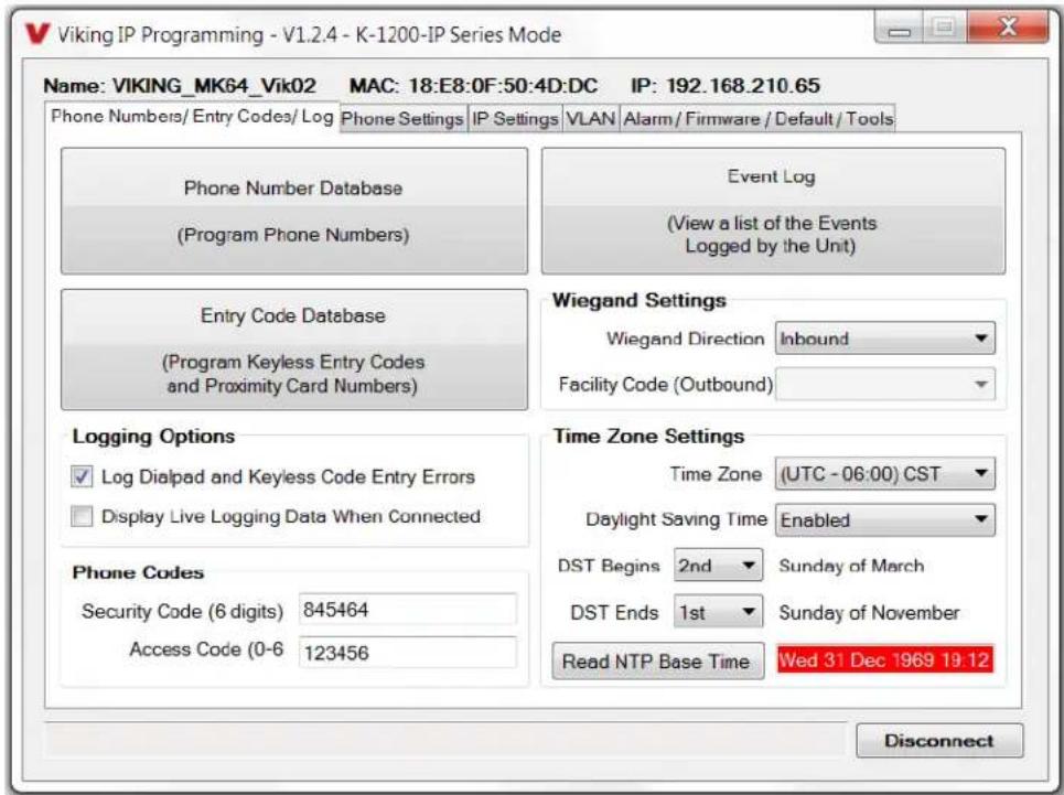
Viking IP Programming - V1.2.4 - K-1200-IP Series Mode Name: VIKING_MK64_Vik02 MAC: 18:E8:0F:50:4D:DC IP: 192.168.210.65 Phone Numbers/Entry Codes/Log Phone Settings IP Settings VLAN Alarm / Firmware / Default / Tools Phone Number Database (Program Phone Numbers) Event Log (View a list of the Events Logged by the Unit) Entry Code Database (Program Keyless Entry Codes and Proximity Card Numbers) Wiegand Settings Wiegand Direction Inbound Facility Code (Outbound) Logging Options Log Dialpad and Keyless Code Entry Errors Display Live Logging Data When Connected Time Zone Settings Time Zone (UTC - 06:00) CST Daylight Saving Time Enabled Phone Codes Security Code (6 digits) 845464 Access Code (0-6) 123456 DST Begins 2nd Sunday of March DST Ends 1st Sunday of November Read NTP Base Time Wed 31 Dec 1969 19:12 Disconnect7. Phone Number Database
Clicking on the "Phone Number Database" button will open a screen allowing you to program all the Tenants Name's, Speed Dial Numbers, and Primary and Roll Over phone numbers. Tenant names are stored locally on the PC and are not uploaded.
The Index Number is the single digit number visitors enter on the K-1275-IP's keypad for the unit to call the tenant. 3 seconds after the number is entered, the unit will then dial the Primary Phone Number associated with that Index Number. If there is no answer or a busy signal is detected, the K-1275-IP will then dial the Roll Over Phone Number. Note: If keyless entry codes are used, leave the # position blank.

text_image
Viking IP Programming - V1.2.4 - K-1200-IP Series Mode Name: VIKING_MK64_Vik02 MAC: 18:E8:0F:50:4D:DC IP: 192.168.210.65 Phone Numbers/Entry Codes/Log Phone Settings IP Settings VLAN Alarm / Firmware / Default / Tools Phone Number Database Event Log (Program Phone Numbers) (View a list of the Events Logged by the Unit) Phone Number Database Index Tenant Name Primary Phone Number Roll Over Phone Number 1 Jim and Marge Thompson 5550101 7155559876 2 Bruce Springfield 5550102 6515556666 3 Frank Thistlewight 5550103 4 George Parker 5550104 7155551346 5 Mark and Mary Mumbles 5550201 7155557890 6 Martin Freeburg 5550202 7155551347 7 Bob and Pat Hendricks 5550203 6125555555 8 Harry and Jane Warner 5550204 6515559639 9 Bob Barker 5550205 7155557378 0 Douglas Adams 5550207 7155550042 * Bob Jones (Building Manager) 7153868861 6515554321Blank for Keyless Entry
Apply Import Export8. Event Log
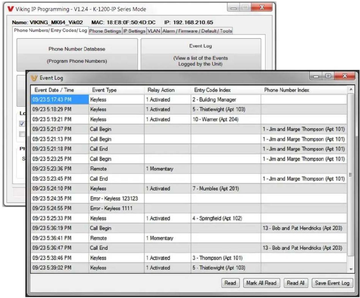
The Event Log button is used to open the Event Log screen. The Event Log screen shows you the time and date of each event, the event type, relay action (which door/gate was opened or closed), entry code index and phone number index with tenant name. The Event Log can store up to 4,095 events. Events are stored in a first in first out format. When the memory is full, new events will over write the oldest events. The Event log can be saved in one of two file formats: Tab Delimited Text or Comma Separated Variable.
text_image
Viking IP Programming - V1.2.4 - K-1200-IP Series Mode Name: VIKING_MK64_Vik02 MAC: 18:E8:0F:50:4D:DC IP: 192.168.210.65 Phone Numbers/Entry Codes/Log Phone Settings IP Settings VLAN Alarm / Firmware / Default / Tools Phone Number Database Event Log (Program Phone Numbers) (View a list of the Events Logged by the Unit) Event Log Event Date / Time Event Type Relay Action Entry Code Index Phone Number Index 09/23 5:17:43 PM Keyless 1 Activated 2 - Building Manager 09/23 5:18:29 PM Keyless 1 Activated 5 - Thistlewight (Apt 103) 09/23 5:19:21 PM Keyless 1 Activated 10 - Warner (Apt 204) 09/23 5:21:07 PM Call Begin 09/23 5:21:13 PM Call Begin 09/23 5:21:18 PM Call End 09/23 5:23:25 PM Call Begin 09/23 5:23:36 PM Remote 1 Momentary 09/23 5:23:45 PM Call End 09/23 5:24:10 PM Keyless 1 Activated 7 - Mumbles (Apt 201) 09/23 5:24:35 PM Error - Keyless 123123 09/23 5:24:55 PM Error - Keyless 1111 09/23 5:25:33 PM Keyless 1 Activated 4 - Springfield (Apt 102) 09/23 5:36:19 PM Call Begin 09/23 5:36:41 PM Remote 1 Momentary 09/23 5:36:47 PM Call End 09/23 5:38:46 PM Keyless 1 Activated 3 - Thompson (Apt 101) 09/23 5:39:02 PM Keyless 1 Activated 5 - Thistlewight (Apt 103) Read Mark All Read Read All Save Event Log9. Entry Code Database
Clicking on the "Entry Code Database" button will open the Entry Code Database screen.
The Entry Code Database will then download, this can take over a minute. The Entry Code Database will allow you to program the Relay Function, Relay 1 or 2, once only (one time use only), Entry Type (Card, Keyless or both), Keyless Code, Proximity Card #, Facility Code, Day of week, Time of Day and Tenant Name. Tenant names are stored locally on the PC and are not uploaded. When "Card + Keyless" is selected, a valid card must be presented and the keyless code entered within 15 seconds.

text_image
Viking IP Programming - V1.2.4 - K-1200-IP Series Mode Name: VIKING_MK64_Vik02 MAC: 18:E8:0F:50:4D:DC IP: 192.168.210.65 Phone Numbers/Entry Codes/Log Phone Settings | IP Settings | VLAN | Alarm / Firmware / Default / Tools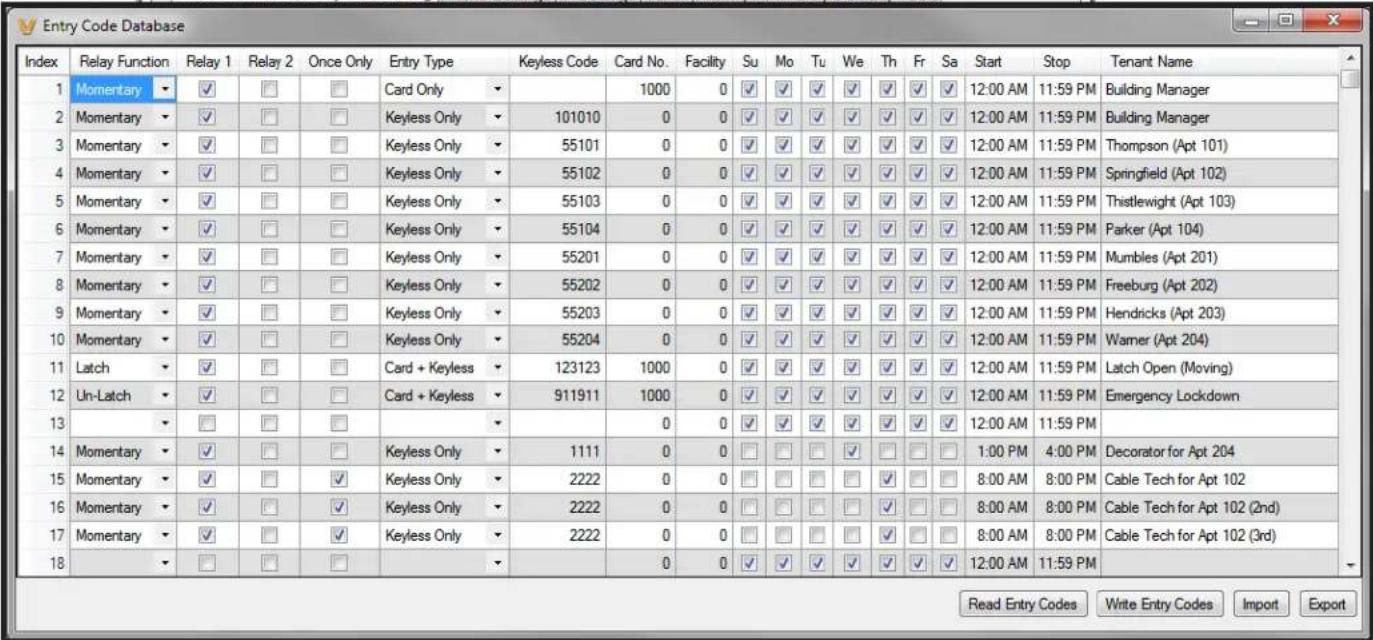
10. Keyless / Card Logging
Keyless Entry Code and Proximity Card logging can be set to Log Errors. With Log Errors selected, (factory setting) the K-1275-IP will not only log all valid Keyless Entry Code and Proximity Card entries, but also log any errors, incorrect codes, or non-valid card reads.
Keyless Entry Code and Proximity Card logging can also be set to Live Logging. With Live logging selected and the K-1275-IP programming software open and connected to a unit, each Keyless Entry Code entered or Proximity Card read will immediately open the Event Log screen and display the latest entry.
11. Security Code
The security code allows the user/installer to program the K-1275-IP Series Phone. It is recommended that the factory set security code be changed. Factory Setting: 845464
Note: The security code must be 6 digits and cannot include a * or a #.
12. Access Code
The Access Code is used for remotely operating the relays (Doorstrike, Mag-Lock, etc) by calling into the unit. This code provides basic security and only allows operation of the relays and not the ability to change any of the programming parameters. Once entered, any of the “Remote Access Operation Commands” can be used. The code can be 1 - 6 digits in length and cannot contain a “*” or “#”. Simply call the K-1275-IP phone, the unit will automatically answer the line and output one beep. You then enter the programmed 1 - 6 digit access code, 2 beeps should be heard. You can now enter any “Remote Access Operation Commands” (see page 22). This code will also enable audio to/from the speaker and the caller. The access code can be cleared (by leaving the field blank) if this additional level of security is not required. Factory Setting: 123456
13. Wiegand Direction
Wiegand Direction allows you to decide if the 26 bit Wiegand connection will be used as an input or an output. The default setting for direction is "Inbound" and this is the correct setting if you intend to connect a card reader or Wiegand keypad device to the wiegand connections.
When the direction is set to "outbound", the 26 bit Wiegand connections become an output and can be connected to the card reader input on the access control system. Unprogrammed keyless entry codes dialed by the user on the keypad are then sent over the Wiegand output. When the user dials "#" plus a entry code that is not programmed in the Entry Code Database, the code dialed by the user is sent over the Weigand output along with the facility code selected. Since Wiegand data limits the entry code to 65535 maximum, "#" plus entry codes higher than 65535 are not sent over the Wiegand output. When the user dials "#" plus a valid keyless entry code that is programmed in the Entry Code Database, the code dialed by the user is not sent over the Wiegand output and the Local / External relay is activated.
14. Select Time Zone
When using date and time logged events or setting the access date and times of keyless codes or proximity cards in the Entry Code Database, you must program the unit to your time zone. Example: You are installing the K-1275-IP in the Central standard time zone: Select (UTC - 06:00) CST, which is 6 hours behind Coordinated Universal Time (UTC). Factory Setting: CST
15. Daylight Savings
The Daylight Savings Time programming can be enabled or disabled and can be programmed to start on any Sunday in March and stopped on any Sunday in November. Currently, daylight saving time starts on the second Sunday in March and ends on the first Sunday in November, with the time changes taking place at 2:00AM local time.
Factory Setting: Enabled
text_image
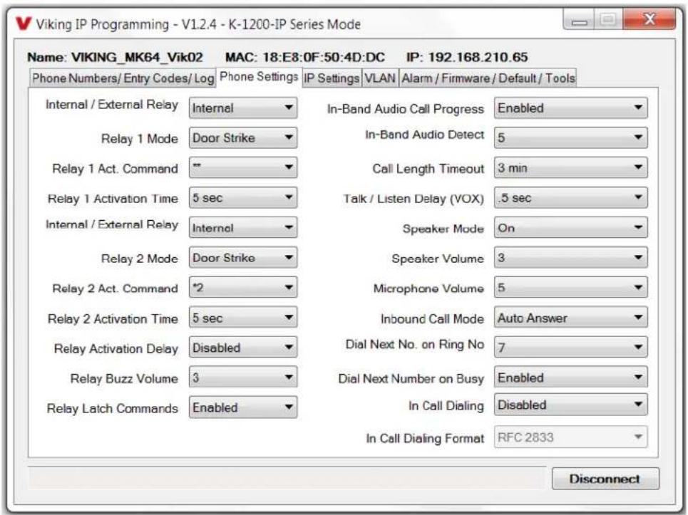
Viking IP Programming - V1.2.4 - K-1200-IP Series Mode Name: VIKING_MK64_Vik02 MAC: 18:E8:0F:50:4D:DC IP: 192.168.210.65 Phone Numbers/Entry Codes/Log Phone Settings IP Settings VLAN Alarm / Firmware / Default / Tools Internal / External Relay Internal In-Band Audio Call Progress Enabled Relay 1 Mode Door Strike In-Band Audio Detect 5 Relay 1 Act. Command " Call Length Timeout 3 min Relay 1 Activation Time 5 sec Talk / Listen Delay (VOX) .5 sec Internal / External Relay Internal Speaker Mode On Relay 2 Mode Door Strike Speaker Volume 3 Relay 2 Act. Command *2 Microphone Volume 5 Relay 2 Activation Time 5 sec Inbound Call Mode Auto Answer Relay Activation Delay Disabled Dial Next No. on Ring No 7 Relay Buzz Volume 3 Dial Next Number on Busy Enabled In Call Dialing Disabled Relay Latch Commands Enabled In Call Dialing Format RFC:2833 Disconnect16. Relay 1 or 2 Internal / External
With relay 1 and/or 2 set to "Internal" the K-1275-IP will activate its on board relays for doorstrike / gate control. Relay 1 and/or 2 should be set to "External" for higher security installations when using a Viking model RC-4A remote relay controller to activate the doorstrike / gate controller (see page 23). Note: With relays set to external the internal on board relays will also activate at the same time as the external relays. Factory Setting: Internal
17. Relay Mode
Doorstrike Mode (Factory Setting): When programmed for Doorstrike Mode the relay will momentarily activate for the preprogrammed relay activation time after detecting the correct relay activation command (one or two digit touch tone) from the called party.
Outbound Call Mode: When programmed for Outbound Call Mode the relay will activate continuously for the duration of any outbound call from the Entry phone.
Inbound/Outbound Call Mode: When programmed for Inbound/Outbound Call Mode the relay will activate continuously for the duration of any inbound or outbound call to or from the Entry phone. This mode is useful for turning on IR flood lights, for VoIP phones with cameras, etc.
Doorbell Mode: When programmed for Doorbell Mode the relay will momentarily activate the relay for the preprogrammed relay activation time at the beginning of any outbound call from the Entry phone. This mode is useful for activating a door chime, etc. When activating door chimes, a 0.5 - 1 second relay activation time is recommended.
Alarm Mode: When programmed in Alarm Mode the relay will activate continuously while the Entry phone is powered and registered to the SIP server. In the event the unit loses power and/or SIP registration the relay will turn off, which can be used to signal an alarm device.
18. Relay 1 or 2 Act (Activation) Command
The one or two digit code stored in the Relay Activation Command is the touch tone command that the person being called must enter on their phone in order to actuate relay 1 or 2 to control a doorstrike, mag-lock, gate controller, or other device. The code can contain the numbers 0 - 9, 00 - 99, ## or **. The code cannot match a relay latching or toggle command (11, 10, 1#, 21, 20, or 2#). The code must be entered while the remote phone is communicating with the Entry phone. The Entry phone determines which direction the touch tone is coming from and only responds to touch tones from the called phone. Factory Setting: Relay 1 - **, Relay 2 - *2
19. Relay 1 or 2 Activation Time
The value stored in the Relay 1 or 2 Activation Time is the amount of time relay 1 or 2 will be energized after a correct momentary touch tone command is entered, “#” plus a valid keyless entry code or a proximity card was scanned that is programmed to momentarily activate the relay. This number can range from 0.5 - 99 seconds. NOTE: This also affects timing in Doorbell Mode. Factory Setting: 5 seconds
20. Relay Activation Delay
A relay activation delay of 0.5 - 99 seconds can be programmed in the K-1275-IP. A relay activation delay is useful in two door vestibule entrance applications. This allows you to program a delay time from when relay 1 (outside door) is activated to when relay 2 (inside door) is activated. The programmed delay time should be set to the average time it takes a person to walk from the outside door to the inside door.
When a request for exit (REX) is activated, relay 2 will activate first, then after the programmed delay relay 1 will activate. Factory Setting: Disabled
21. Relay Buzz Volume
The relay activation tone is a buzzing sound that is heard at the Entry phone when the door strike relay is activated. After the called party enters the correct relay activation command, the called party will hear 2 short confirmation beeps and the entry phone will output a buzzing sound (relay activation tone) while the door strike relay is activated. The tone (buzz) length will match the relay activation time up to a maximum of 5 seconds. The tone (buzz) can be programmed to three different volume settings 1 = Low, 2 = Medium, 3 = High or it can be disabled. Factory Setting: 3
22. Relay Latch Commands
When set to "Enabled" the Remote Access Operation Commands to Un-Latch or Latch the relay are enabled.
When set to "Disable" the Remote Access Operation Commands to Un-Latch or Latch the relay are disabled. Disabling the Latch commands can be useful in applications where you want to eliminate the possibility of inadvertently entering a latch command leaving a gate open/closed, etc. The relays can still be activated with the "Relay Activation Command" for momentary closures. Factory Setting: Enabled
23. In-Band Audio Call Progress
The In-Band Audio Call Progress Detection can be set to enabled or disabled. In-Band Audio Call Progress detection should be enabled in applications where you are making an outbound call through your VoIP phone system and are relying on In-Band analog audio for ringback or busy detection. Factory Setting: Enabled.
24. In-Band Audio Detect Sensitivity
The In-Band Audio Detect level (Sensitivity) can be set from 1 - 9, 1 = minimum setting, 9 = highest setting. Increasing or decreasing the sensitivity may be required in applications where you are making an outbound call through your VoIP phone system and are relying on In-Band analog audio detection. Factory Setting: 5
25. Call Length Time Out
This feature selects the maximum length of time that calls can be connected. Programmable in increments of 1 minute up to a maximum of 9 minutes or disabled. With the call length disabled, the K-1275-IP phone must rely on a call ended signal, busy signal, Ring No Answer limit, or touch tone “#” command to hang-up. Factory Setting: 3 minutes
Note: Timer starts after call is connected. If call is not answered (and ring no answer disabled) there is a default 7 minute timer.
26. Talk / Listen Delay (VOX)
This feature selects switching time between talk and listen modes (VOX switching time). The Talk/Listen Delay can be programmed from 0.1 - 0.9 seconds. Factory Setting: 0.5 seconds
27. Speaker Mode
The Speaker Mode will be set to one of the following two modes. This is selected automatically based on Inbound Call Mode.
OFF/Silent Monitoring Mode: In the "OFF" mode the speaker is disabled on inbound calls. However, the speaker can be enabled after communication has been established by entering touch tone command "9#". The speaker will then remain on for the duration of the call.
ON (Factory Setting): In the "ON" mode the speaker is enabled during In-bound and Out-bound calls.
28. Speaker Volume
The speaker volume can be set from 0 - 9, 0 = lowest volume setting, 9 = highest volume setting. Alternatively the speaker can be turned off for silent monitoring (see Speaker Mode section 27). Factory Setting: 3
29. Microphone Volume / Automatic Noise Cancelling Mode
The microphone volume can be set from 1 - 9, 1 = lowest volume setting, 9 = the highest volume setting. Alternatively the microphone can be placed in the "Auto" (Automatic Noise Cancelling) mode. With the mic in the Auto mode, when background noise increases, the mic gain will automatically decrease. When background noise decreases the mic gain will automatically increase. The Auto mode is useful in applications where the background noise level can change drastically such as a gas car running vs a diesel truck. Factory Setting: 5 seconds
30. Inbound Call Mode
The Inbound Call Mode determines how the K-1275-IP handles incoming SIP calls. One option is to auto answer a SIP call to transmit a page, control the relay or listen to transmit audio from the microphone. Another option is the silent monitor mode, which allows callers to listen to the transmit audio from the microphone. The “secure” options for auto answer require the callers to dial the access code in order to transmit a page, activate the relay or activate the optional RC-4A relays. Factory Setting: Auto Answer
Disabled: In the "Disabled" mode the phone will not automatically answer an incoming call.
Auto Answer: In the "Auto Answer" mode the phone will automatically answer an incoming call on the first ring.
Auto Answer Secure – Inbound calls are auto answered and the caller must dial the access code in order to listen or talk on the unit.
Silent Monitor – Inbound calls are auto answered and the caller hears transmit audio from the microphone at a much higher volume level.
Silent Monitor Secure – Inbound calls are auto answered and the caller must dial the access code in order to listen to transmit audio from the microphone (volume level is still at a much higher volume level).
Note: For Silent Monitor mode(s), the speaker can be enabled by dialing 9# from the connected phone.
31. Dial Next number on Ring No Answer
If enabled and a ring-no-answer is detected, the K-1275-IP phone will dial the "Roll Over" speed dial number after the programmed amount of rings. A momentary press of the call button will dial the first programmed Speed Dial number. This can be set from 1 - 9 rings. Factory Setting: 7 (will redial after 7 rings)
32. Dial Next Number on Busy
If enabled and a busy is detected, the K-1275-IP phone will dial the "Roll Over" speed dial number.
Factory Setting: Enabled
Note: If the busy signal is interrupted with a promotional message, contact your central office to have it removed.
33. In Call Dialing
In Call Dialing refers to the numbers dialed (from the K-1275-IP's keypad) after an outbound call has been answered by the distant party. This would typically be the numbers dialed to steer through automated attendants, voice mail, etc.
Factory Setting: Disabled
34. In Call Dialing Format
The In Call Dialing Format can be set to In-Band DTMF (Touch Tones) or RFC 2833 (Out of Band DTMF Touch Tones). In Call dialing refers to the numbers dialed (from the K-1275-IP's keypad). after an outbound call has been answered by the distant party. This would typically be the numbers dialed to steer through automated attendants, voice mail, etc. If your VoIP phone system does not automatically convert out of band DTMF to In-Band after the call is answered, set In Call Dialing Format to "Inband DTMF". Factory Setting: RFC 2833

text_image
Viking IP Programming - V1.2.4 - K-1200-IP Series Mode Name: VIKING_MK64_Vik02 MAC: 18:E8:0F:50:4D:DC IP: 192.168.210.65 Phone Numbers/Entry Codes/Log Phone Settings IP Settings VLAN Alarm/Firmware/Default/Tools Dynamic IP Settings Unit IP Address 192.168.210.65 Subnet Mask 255.255.255.0 Gateway IP Address 192.168.210.18 These are the current / last known good IP addresse Firmware Versions IP R6.35.1834 Update IP Unit V2.0 Update Unit Import / Export Import Data Export Data SIP / Network Failure Alarm SIP Registration Status Not Registered Current Alarm Status Activated - SIP Alarm Muted Mute Current / Next Permanent Alarm Muto Alarm Tones Enabled Alarm can be triggered by unit failing to register with SIP server, Gateway ping failure, or IP address conflict (if unit forced to use static) Default Unit Settings Clear Phone Settings Clear IP Settings Diagnostics Test Relay 1 Test Relay 2 Read Status Last Read Relay Status Test Mic/Spk Read Card # Disconnect35. Mute Current / Next Alarm
A network failure alarm will be indicated by providing 3 beeps every 30 seconds. A network failure indicates the unit is not registered to the SIP server or there is a communication failure with the gateway. The three beeps can be muted by clicking on "Mute Current / Next Alarm". The Status LED will continue to flash to assist troubleshooting. The alarm beeps can also be permanently disabled. See Permanent Alarm Mute.
36. Permanent Alarm Mute
Selecting "Alarm Tones Disabled" will mute all alarm tones indefinitely. To re-enable alarm tones select "Alarm Tones Enabled". Factory Setting: Alarm Tones Enabled
37. IP Firmware
If new K-1275-IP firmware is available, after opening the programming software a pop window will come up asking you if you would like to update firmware. An alternative method of updating can be done by clicking the IP firmware "Update IP" button. You can then browse to the folder that contains the PIP file for updating the unit's IP firmware. This method is typically only used when Viking Technical Support has sent you updated IP firmware.
38. Unit Firmware
If new K-1275-IP firmware is available, after opening the programming software a pop window will come up asking you if you would like to update firmware. An alternative method of updating can be done by clicking the Unit firmware "Update Unit" button. You can then browse to the folder that contains the HEX file for updating the unit's firmware. This method is typically only used when Viking Technical Support has sent you updated firmware.
39. Import/Export
The Import/Export feature is useful for backing up all the K-1275-IP's programming or for importing programming when installing multiple units with a majority of the same programming.
40. Clear Unit Settings
Clicking on the "Clear Unit settings" button in programming will reset all of the Programming Features back to their factory default settings. Note: This command will not change or reset your IP settings.
41. Clear IP Settings
Clicking on the "Clear IP Settings" will reset all of the IP settings back to their factory default settings. This also clears paging Group settings and Addresses. Note: This will not effect any speaker or paging settings.
42. Diagnostics
The Diagnostics section in the Viking IP Programming can be used to test the functionality of the two relays, read current relay status, perform mic/spkr diagnostics, or to display information on the last card or fob detected by the card reader.
43. REX Input
The K-1275-IP has one Request for Exit (REX) trigger input. The REX switch must have a momentary, normally open contact. When the K-1275-IP detects a contact closure on the REX trigger input it performs one of the following actions, based on the Relay Mode settings for each relay (see section 22):
Relay 1 "Door Strike", relay 2 other: Relay 1 will be activated for the programmed Relay 1 Activation Time.
Relay 1 other, relay 2 "Door Strike": Relay 2 will be activated for the programmed Relay 2 Activation Time.
Relay 1 "Door Strike", relay 2 "Door Strike": If the Relay Activation Delay is disabled, Relay 2 will be activated for the programmed Relay 2 Activation Time. If Relay Activation Delay is not disabled, Relay 2 will be activated for the programmed Relay 2 Activation Time, then after the Relay Activation Delay time has passed, Relay 1 will be activated for the programmed Relay 1 Activation Time. This is useful in two door vestibule applications where Relay 1 is used to unlock the outside door, and Relay 2 is used to unlock the inside door.
Note: For security reasons this input is disabled when the relay is set to "External".
Operation
A. Keypad
When a Keypad button is pressed, the K-1275-IP immediately dials the pre-programmed telephone number stored in the corresponding Phone Number Database Index location (1-#). The Call Status LED momentarily flashes during dialing. In the event the line is busy or there is a ring-no-answer, the unit can be programmed to call a second roll over number.
When the call is answered, relay activation commands can be entered or the # key can be used to force the phone to hang-up.
After communication is established, enter the 1 or 2 digit relay activation command (factory set to “**” for Relay 1 and “*2” for Relay 2) to momentarily activate the entry phone (door strike) relay. Two beeps will be heard confirming that the relay has been activated. If you require the relay to remain on continuously (ie: a truck delivery), enter Touch Tones “11” or “21” to continuously activate relay 1 or relay 2 respectively. A double beep will indicate that the relay is latched on. When the visitor calls in again (ie: they are finished unloading the truck), enter Touch Tones “10” or “20” to deactivate relay 1 or relay 2 respectively. A single beep will indicate the relay is latched off. The relays can be toggled by entering “1#” and “2#” for relays 1 and 2.
B. Remote Access Operation Commands
The following commands can be entered after answering an inbound call from the entry phone. The commands can also be entered on an outbound call to the entry phone. After the entry phone auto answers the call, one or two beeps will be heard. If the access code has been disabled (two beeps heard), you can now enter the Remote Access Operation Commands below. If an Access code has been programmed (one beep heard), enter the Access code digits. With the correct code entered, two beeps will be heard and you can now enter the Remote Access Operation Commands below. The relay must be set to "Door Strike" Mode to be controlled by these commands.
| Feature | Touch Tone Command | Description |
| Momentarily Activate Relay 1 | ** or ____ | Momentarily activate relay 1 (1 or 2 digits, factory set to **). |
| Latch Relay 1 11 Latch* (continuously activate) relay 1. | ||
| Un-Latch Relay 1 10 Un-latch* (deactivate) relay 1. | ||
| Toggle Relay 1 1# Toggle* relay 1 from last position. | ||
| Momentarily Activate Relay 2 | *2 or ____ | Momentarily activate relay 2 (1 or 2 digits, factory set to *2). |
| Latch Relay 2 21 Latch* (continuously activate) relay 2. | ||
| Un-Latch Relay 2 20 Un-latch* (deactivate) relay 2. | ||
| Toggle Relay 2 2# Toggle* relay 2 from last position. | ||
| Disconnect # Disconnects or forces the phone to hang up. | ||
* Note: Relay latch commands must be enabled in programming.
C. Keyless Entry Codes and One Time Use Keyless Entry Codes
Keyless entry codes may be used by the tenants to provide keyless entry. The K-1275-IP can be programmed with a combination of up to 1000* keyless entry codes or one time use keyless entry codes. The keyless entry codes can be programmed to be from 1 to 6 digits in length. Each keyless entry code can be programmed to activate relay 1 and/or 2 in four different relay modes: Momentary, Latch, Un-Latch and Toggle. To use a keyless entry code the tenant simply dials “#” followed by the entry code on the K-1275-IP's keypad. After the one time use keyless entry code has been used, it is instantly cleared from the unit's memory. This is ideal for issuing keyless entry codes to service personnel, etc.
Notes: 1. A short buzz sound indicates when the relay has been activated and the visitor can now open the door. 2. If keyless entry codes are used, leave the “#” position blank in the Phone Number Database.
D. Proximity Cards / Fobs
Proximity cards or Fobs can also be used by the tenants to provide keyless entry. The K-1275-IP can be programmed with up to 1000* proximity card numbers. Each proximity card number can be programmed to activate relay 1 and/or 2 in four different relay modes: Momentary, Latch, Un-Latch and Toggle. To use a proximity card the tenant simply presents a preprogrammed proximity card within **6 inches of the proximity card reader attached to the K-1275-IP. A short beep will be heard from the card reader indicating a card scan. If the card matches a valid preprogrammed card number a short buzz sound (if enabled) will be heard indicating the relay has been activated and the visitor can now open the door or gate.
* Note: 1000 is the total number of Keyless Entry Codes and/or Proximity Card numbers that can be programmed in the Entry Code Database.
** Note: Read range is dependent on the card reader type.
Troubleshooting
If the unit cannot register with the programmed SIP server, the LED will blink on and off every second, and three error beeps will be heard every 30 seconds until communication is restored. This alerts a potential user of a problem with the device that will prevent an entry phone call from being made.
You may silence the error beeps, per instance, by pressing and holding the “*” button on the keypad for 5 seconds or by clicking the “Mute Alarm Until Next Failure” button in the Viking IP Programming Software (see section 35 on page 20). The error beeps automatically re-enable once the unit is registered, to alert of any new problems that arise.
Optional Secure Remote Relay Control Using a Viking Model RC-4A

flowchart
graph TD
    A["12V DC Adapter (included)"] --> B["VOKING MODEL RC-4A"]
    B --> C["RELAY 1"]
    B --> D["RELAY 2"]
    B --> E["RELAY 3"]
    B --> F["RELAY 4"]
    B --> G["STATUS LED"]
    B --> H["LOGIC LEVEL PROGRAMMING RESTORE DEFAULTS SPARE"]
    B --> I["NETWORK"]
    B --> J["Network"]
    K["Door near Entry Phone 1"] --> L["Relay 1 Output Contacts (5A@30VDC / 250VAC max)"]
    L --> M["120V AC"]
    L --> N["Doorstrike / Magnetic Lock"]
    L --> O["COM."]
    L --> P["N.O."]
    Q["Gate near Entry Phone 2"] --> R["Relay 2 Output Contacts (5A@30VDC / 250VAC max)"]
    R --> S["Gate Controller"]
    R --> T["COM."]
    R --> U["N.O."]
    V["Door near Entry Phone 3"] --> W["Relay 3 Output Contacts (5A@30VDC / 250VAC max)"]
    W --> X["120V AC"]
    W --> Y["Doorstrike / Magnetic Lock"]
    W --> Z["COM."]
    W --> AA["N.O."]
    AB["Sensor Examples"] --> AC["Door Sensor"]
    AB --> AD["Gate Sensor"]
    AB --> AE["Door Sensor"]
    AB --> AF["Door Sensor"]
    AG["Door near Entry Phone 4"] --> AH["Relay 4 Output Contacts (5A@30VDC / 250VAC max)"]
    AH --> AI["120V AC"]
    AH --> AJ["COM."]
    AH --> AK["N.O."]
    AL["SIP VoIP PBX, SIP Cloud based Service Provider or PC with SIP Server Software"] --> AM["Internet"]
    AM --> AN["PoE Switch"]
    AN --> AO["K-1275-IP Entry Phone 1"]
    AN --> AP["K-1275-IP Entry Phone 2"]
    AN --> AQ["K-1275-IP Entry Phone 3"]
    AN --> AR["K-1275-IP Entry Phone 4"]
The front panel of the K-1275-IP is mounted using security Torx screws to help prevent intruders from removing the panel and accessing the on board door strike/gate control relays. For applications requiring additional security, a Viking model RC-4A remote relay controller can be used. The relay controller is mounted securely inside the building and connected to the same LAN as the K-1275-IP. The on board door strike relays would not be used in this case as the K-1275-IP will send an encrypted message to the RC-4A to activate its relays which control the door strikes/gates. For more information, see DOD# 582 at www.VikingElectronics.com.
Up to 4 K-1275-IP's can communicate with one RC-4A allowing you to securely control four entrances.
When using an RC-4A for remote relay control the K-1275-IP's relays should be set to "External" in the PC programming.
Note: If the K-1275-IP loses communications with the RC-4A, the LED on the front panel of the K-1275-IP will flash 3 times every 2 seconds indicating the communication error. If this error occurs, make sure the RC-4A is powered, has a network connection and has the correct IP address and security code of the K-1275-IP displaying errors.
Related Products
Surface or Pedestal Mount Viking Products While Maintaining Weather and Vandal Resistance
The VE-3x5, VE-5x5, VE-6x7 and VE-5x10 add vandal and weather resistance, as well as versatility to many Viking products. The VE-Series backboxes are available in black fine texture powder painted steel or marine grade 316 stainless steel. The weather resistant boxes are designed to be surface mounted to a wall, post, single gang box, or a VE-GNP gooseneck pedestal. Note: The VE-3x5 is not compatible with the VE-GNP pedestals and is not available in stainless steel.

text_image
VE-GNP-2 VE-GNP-IG VE-GNP-SS VE-GNP The V are d VE-5x backb up c VE-3x VE-GThe VE-GNP gooseneck pedestals are designed to be used with the VE-5x5, VE-6x7 and VE-5x10 backboxes and are ideal for drive up communications. Note: The VE-3x5 is not compatible with the VE-GNP pedestals.
natural_image
Six different metal enclosure units with varying internal cutouts, displayed side by side (no text or symbols visible on the boxes themselves)
natural_image
Four different metal enclosure units labeled VE-6x7VE-6x7-SSVE-6x7-PNL and VE-6x7-PNL-SS, shown from different angles (no additional text or symbols visible)
natural_image
Six different metal enclosure units, each labeled with a unique identifier (e.g., VE-5x10-NRVE-5x10-NR-SS), shown from different angles and sizes.The VE-PNL's are VE-Series backboxes with a blank aluminum panel. The user can customize the clear-coated aluminum panel to mount an PRX-1 card reader, PRX-2 keypad or switch. The kits come complete with box, gasket, panel and screws. Model numbers that end with "SS" are stainless steel version. Note: The use of magnets to mount the VE-Series enclosure to a metal surface can affect the operation of the enclosed product.
Caution: Handsfree phones are not suitable for noisy applications (see "Important" on page 2).
For more information on Viking Surface Mount Boxes and Pedestals, see DOD 424.
Add Panel Lighting to Your Viking VoIP Entry Phone
The VE-LIGHT kit adds bright LED illumination to any VoIP entry phone that is housed in a Viking VE-5x5, VE-6x7 or VE-5x10 enclosure.
The stainless steel bracket is easily mounted using existing holes and hardware. Two bright white LEDs are used as the light source, so there are no filaments to break or bulbs to burn out.
12 VDC power adapter included. Any power source between 12 and 24 volts, AC or DC can be used to supply the VE-LIGHT with power. The K-1275-IP provides 12 VDC for this. See features on page 4.
For more information, See DOD 428.
VE-LIGHT shown right with Viking E-30 and VE-5x5 (not included)
text_image
Call VIKING.Related Products
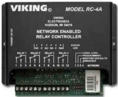
Control Relay Contacts Across a Local Area Network
The RC-4A Network Enabled Relay Controller provides networked control of four relays via an easy-to-use web interface. The same interface can be used to check the status of four contact closure inputs. Relays can be toggled on or off, or user-programmed timed closures can be activated.
The RC-4A can be configured to work as a remote relay for Viking VoIP series entry phones, controlling door strikes and gates when a remote relay is required for security reasons. It can also be programmed to send an email or text message in response to a change in one or more of the sensor inputs. Two RC-4A's can be set up so that activity on a sensor input of one unit will automatically send a message across the network to activate one of the relays on the other unit. Two levels of user access permit selected users to have full operational and programming rights while others have operational control but not programming capability.
text_image
VIKING® MODEL RC-4A VIKING ELECTRONICS HUDSON, WI 54016 NETWORK ENABLED RELAY CONTROLLER STATUS LED LOGIC LEVEL PROGRAMMING RESTORE DEFAULTS PERFORMANCE NETWORKFor more info, see DOD 582
Long Range 4 Channel Transmitters and Receivers

Viking's model LTR-4 Long Range Wireless 4 Channel Radio Transmitters and LRR-4 Long Range 4 Channel Receivers with integrated receive antenna comprise Vikings high frequency, long-range (RFID) identification solution. Intended for security access control applications, the LRT-4's wireless communication is based upon a secure, digital, anti-playback routine. The LRT-4 Transmitters have four buttons, each corresponding to its own Wiegand output on the LRR-4 Receiver. Each Transmitter includes an integrated red LED, used to indicate both positive button press and battery strength. They are also equipped standard with a 125KHz HID** compatible potted proximity module allowing the Transmitter to also be used as a close range access credential.
The transmitters and receivers operate at 433-MHz allowing a transmission range of up to 400 ft (line of sight). The LRR-4 receiver has an adjustable read range, optional external antenna connector, terminal block with 4 channel Wiegand data output and a transducer and LED to confirm transmitter button press. The LRR-4 has a conformal coated circuit board mounted in a NEMA 4, 4x rated box for use in outdoor applications. See DOD 226 for more information.
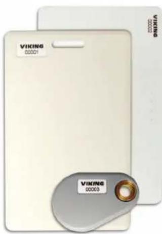
125KHz Proximity Cards
The PRX-C and PRX-C-ISO are non-contact security cards that can be presented to the front of a K-1770/75-IP proximity card reader to allow entrance into a secured area. The PRX-C is a clam shell card made made from 0.070" thick plastic to resist bending and folding. A slot is provided at one end to allow a lanyard to be added for creating a "dog tag" style neck strap. The PRX-C-ISO is a thin 0.032" thick flexible "ISO" style proximity card. Much like a credit card, the PRX-C-ISO is perfect for storing in your wallet.
text_image
VIKING 00001 VIKING 00003The PRX-FOB is a proximity key ring fob with brass eyelet designed to attach to a key chain or necklace. The PRX-FOB's compact size is only 1.5" x 1.2" x 0.15" making it one of the smallest available.
The cards and fobs are custom pre-programmed. For more information see DOD 198.
Medium Range 125KHz Proximity Card Reader
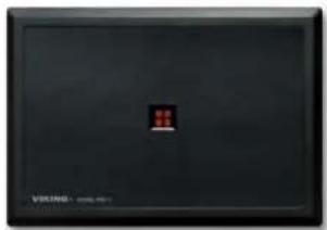
natural_image
Black rectangular electronic device with a small red indicator light on the front panel (no visible text or symbols)PRX-3
The model PRX-3 is a high performance medium range 125KHz proximity card reader. The PRX-3's compact size yet long read range of up to 16 inches* make it ideal for parking control, gate access, turnstiles, etc. It is designed to be mounted directly to a wall, post, single gang electrical box or use an optional mounting kit for attaching it to a gooseneck pedestal. Mounting is simplified with horizontal and vertical mounting slots, which allow the reader to be conveniently adjusted and leveled. To increase vandal resistance the chassis is a single piece design with the mounting screws concealed behind a UV stable label.
The proximity card reader transmits data in 26-Bit Wiegand format, making it compatible with any of the Wiegand equipped Viking entry controllers. The PRX-3 is equipped with Enhanced Weather Protection (EWP) for outdoor installations where the unit is exposed to precipitation or condensation. With its sealed connections and fully potted electronics the PRX-3 is designed to meet an IP66 Ingress Protection Rating. For more information see DOD 228.
Gooseneck Pedestal Mounting Kit

text_image
PRX-3 shown with VE-GNP pedestal, PRX-3-MK-VEGNP mounting kit and K-1700-IP with VE-6x7For more info see DOD 229
The model PRX-3-MK-VEGNP is a mounting kit for attaching the PRX-3 proximity card reader and a VE-5x5, VE-6x7 or VE-5x10 (surface mount entry phone box) to a VE-GNP gooseneck pedestal. It includes the required mounting hardware, has a mounting plate made from durable 3/8 inch thick black UV stable textured ABS plastic and a gasket for sealing the back side of the VE surface mount box.

natural_image
Black rectangular object with a central oval and four side markings (no text or symbols visible)Warranty
IF YOU HAVE A PROBLEM WITH A VIKING PRODUCT, CONTACT VIKING TECHNICAL SUPPORT: 715-386-8666
Our Technical Support Department is available for assistance Monday through Friday 8:00am to 5:00pm central time. So that we can give you better service, before you call please:
- Know the model number, the serial number and what software version you have (see serial label).
- Have the Product Manual in front of you.
- It is best if you are on site.
RETURNING PRODUCT FOR REPAIR
The following procedure is for equipment that needs repair:
- Customer must contact Viking's Technical Support Department at 715-386-8666 to obtain a Return Authorization (RA) number. The customer MUST have a complete description of the problem, with all pertinent information regarding the defect, such as options set, conditions, symptoms, methods to duplicate problem, frequency of failure, etc.
- Packing: Return equipment in original box or in proper packing so that damage will not occur while in transit. The original product boxes are not designed for shipping - an overpack box is required to prevent damage in transit. Static sensitive equipment such as a circuit board should be in an anti-static bag, sandwiched between foam and individually boxed. All equipment should be wrapped to avoid packing material lodging in or sticking to the equipment. Include ALL parts of the equipment. C.O.D. or freight collect shipments cannot be accepted. Ship cartons prepaid to:
VIKING ELECTRONICS 1531 INDUSTRIAL STREET HUDSON, WI 54016
-
Return shipping address: Be sure to include your return shipping address inside the box. We cannot ship to a PO Box.
-
RA number on carton: In large printing, write the RA number on the outside of each carton being returned.
RETURNING PRODUCT FOR EXCHANGE
The following procedure is for equipment that has failed out-of-box (within 10 days of purchase):
- Customer must contact Viking's Technical Support at 715-386-8666 to determine possible causes for the problem. The customer MUST be able to step through recommended tests for diagnosis.
- If the Technical Support Product Specialist determines that the equipment is defective based on the customer's input and troubleshooting, a Return Authorization (RA) number will be issued. This number is valid for fourteen (14) calendar days from the date of issue.
- After obtaining the RA number, return the approved equipment to your distributor. Please reference the RA number on the paperwork being shipped back with the unit(s), and also the outside of the shipping box. The original product boxes are not designed for shipping - an overpack box is required to prevent damage in transit. Once your distributor receives the package, they will replace the product over the counter at no charge. The distributor will then return the product to Viking using the same RA number.
- The distributor will NOT exchange this product without first obtaining the RA number from you. If you haven't followed the steps listed in 1, 2 and 3, be aware that you will have to pay a restocking charge.
TWO YEAR LIMITED WARRANTY
Viking warrants its products to be free from defects in the workmanship or materials, under normal use and service, for a period of two years from the date of purchase from any authorized Viking distributor. If at any time during the warranty period, the product is deemed defective or malfunctions, return the product to Viking Electronics, Inc., 1531 Industrial Street, Hudson, WI., 54016. Customer must contact Viking's Technical Support Department at 715-386-8666 to obtain a Return Authorization (R.A.) number.
This warranty does not cover any damage to the product due to lightning, over voltage, under voltage, accident, misuse, abuse, negligence or any damage caused by use of the product by the purchaser or others. This warranty does not cover non-EWP products that have been exposed to wet or corrosive environments. This warranty does not cover stainless steel surfaces that have not been properly maintained.
NO OTHER WARRANTIES. VIKING MAKES NO WARRANTIES RELATING TO ITS PRODUCTS OTHER THAN AS DESCRIBED ABOVE AND DISCLAIMS ANY EXPRESS OR IMPLIED WARRANTIES OR MERCHANTABILITY OR FITNESS FOR ANY PARTICULAR PURPOSE.
EXCLUSION OF CONSEQUENTIAL DAMAGES. VIKING SHALL NOT, UNDER ANY CIRCUMSTANCES, BE LIABLE TO PURCHASER, OR ANY OTHER PARTY, FOR CONSEQUENTIAL, INCIDENTAL, SPECIAL OR EXEMPLARY DAMAGES ARISING OUT OF OR RELATED TO THE SALE OR USE OF THE PRODUCT SOLD HEREUNDER.
EXCLUSIVE REMEDY AND LIMITATION OF LIABILITY. WHETHER IN AN ACTION BASED ON CONTRACT, TORT (INCLUDING NEGLIGENCE OR STRICT LIABILITY) OR ANY OTHER LEGAL THEORY, ANY LIABILITY OF VIKING SHALL BE LIMITED TO REPAIR OR REPLACEMENT OF THE PRODUCT, OR AT VIKING'S OPTION, REFUND OF THE PURCHASE PRICE AS THE EXCLUSIVE REMEDY AND ANY LIABILITY OF VIKING SHALL BE SO LIMITED.
IT IS EXPRESSLY UNDERSTOOD AND AGREED THAT EACH AND EVERY PROVISION OF THIS AGREEMENT WHICH PROVIDES FOR DISCLAIMER OF WARRANTIES, EXCLUSION OF CONSEQUENTIAL DAMAGES, AND EXCLUSIVE REMEDY AND LIMITATION OF LIABILITY, ARE SEVERABLE FROM ANY OTHER PROVISION AND EACH PROVISION IS A SEPARABLE AND INDEPENDENT ELEMENT OF RISK ALLOCATION AND IS INTENDED TO BE ENFORCED AS SUCH.
If trouble is experienced with the K-1275-IP Series phone, for repair or warranty information, please contact:
Viking Electronics, Inc., 1531 Industrial Street, Hudson, WI 54016 715-386-8666
WHEN PROGRAMMING EMERGENCY NUMBERS AND (OR) MAKING TEST CALLS TO EMERGENCY NUMBERS:
Remain on the line and briefly explain to the dispatcher the reason for the call. Perform such tests in off-peak hours, such as early morning or late evenings.
PART 15 LIMITATIONS
This equipment has been tested and found to comply with the limits for a Class A digital device, pursuant to Part 15 of the FCC Rules. These limits are designed to provide reasonable protection against harmful interference when the equipment is operated in a commercial environment. This equipment generates, uses, and can radiate radio frequency energy and, if not installed and used in accordance with the instruction manual, may cause harmful interference to radio communications. Operation of this equipment in a residential area is likely to cause harmful interference in which case the user will be required to correct the interference at his own expense.
CANADA
Due to the dynamic nature of the product design, the information contained in this document is subject to change without notice. Viking Electronics, and its affiliates and/or subsidiaries assume no responsibility for errors and omissions contained in this information. Revisions of this document or new editions of it may be issued to incorporate such changes.