SFTE - Flow detector Festo - Free user manual and instructions
Find the device manual for free SFTE Festo in PDF.


| Product Type | Pneumatic Cylinder/Sensor Unit |
| Manufacturer | Festo |
| Model | SFTE |
| Dimensions (approx.) | Length: 150 mm, Diameter: 20 mm |
| Weight | 0.3 kg |
| Operating Pressure | 2 to 8 bar |
| Ambient Temperature Range | -10°C to 60°C |
| Protection Class | IP40 |
| Material | Aluminum alloy, plastic housing |
| Electrical Connection | M12 connector, 4-pin |
| Supply Voltage | 24 V DC |
| Power Consumption | < 1 W |
| Output Signal | PNP/NPN, analog or digital depending on variant |
| Functions | Position sensing, pressure monitoring, end-of-stroke detection |
| Maintenance | Periodic cleaning of connector; no lubrication required |
| Cleaning Instructions | Wipe with dry or mildly damp cloth; do not use solvents |
| Safety Precautions | Disconnect power before installation; ensure proper pressure range |
| Spare Parts & Repairability | Replacement connectors and mounting brackets available; unit is not field-repairable |
| Certifications | CE, RoHS |
| Warranty | 2 years |
Frequently Asked Questions - SFTE Festo
User questions about SFTE Festo
0 question about this device. Answer the ones you know or ask your own.
Ask a new question about this device
Download the instructions for your Flow detector in PDF format for free! Find your manual SFTE - Festo and take your electronic device back in hand. On this page are published all the documents necessary for the use of your device. SFTE by Festo.
USER MANUAL SFTE Festo
natural_image
Technical line drawing of a mechanical component with no visible text or symbolsFESTO
Festo SE & Co. KG
Ruiter Straße 82
73734 Esslingen
Germany
+49 711 347-0
www.festo.com
Instructions | Operating
8035274
2018-06
[8035276]


Translation of the original instructions
1 Further applicable documents
All available documents for the product → www.festo.com/pk.
2 Safety
2.1 Intended use
The SFTE is intended for detecting the flow of gaseous media in piping systems or terminals in the industry sector.

WARNING!
Risk of injury from prohibited media.
Use of the product in combination with prohibited media can result in personal injury.
- Do not use the product with flammable or corrosive gases.
NOTICE!
Product damage due to incorrect air quality class.
Condensation water, oil mist, foreign matter and other dirt in the compressed air can damage the product and cause incorrect measurements and malfunctions.
- Adhere to the specified air quality class for the operating medium.
2.2 General safety instructions
- The product may only be used in its original status without unauthorised modifications.
- Only use the product if it is in perfect technical condition. Electrical output
- Take into consideration the ambient conditions at the location of use.
- Comply with all applicable national and international regulations.
- Do not use the product in combination with inflammable, caustic, vapour-emitting or other hazardous media.
- Check the operating medium to determine compatibility with the materials it contacts.
- Observe the specifications on the product labelling.
- Remove all transport packaging. Recycle packaging material.
3 Service
- If you have technical questions, contact the regional Festo contact at
→ www.festo.com.
4 Accessories
Accessories → www.festo.com/catalogue.
5 Product overview
5.1 Design
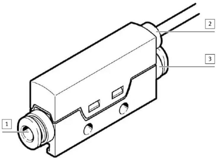
1 Pneumatic connection (inlet)
2 Electrical connection
Fig. 1
3 Pneumatic connection (outlet)
5.2 Product variants and type code
| Feature Value Description | ||
| Type SFTE Flow transmitter | ||
| Flow measuring range | -1 Max. 1 l/min | |
| -2 Max. 2l/min | ||
| -5 Max. 5 l/min | ||
| -10 Max. 10 l/min | ||
| Flow input r Unidirectional | ||
| Pneumatic connection | -Q3 Push-in connector 3 mm | |
| -Q4 Push-in connector 4 mm | ||
| -M5 M5 | ||
| NoneThread type | ||
| F Female thread | ||
| -B 1 ... 5 V | ||
| -V 0 ... 10 V | ||
| Electrical connection | -2.5K | Cable 2.5 m, open end |
| -0.3M8 | Cable 0.3 m, with plug connect-or M8 |
Tab. 1
6 Function
The SFTE detects the flow rate (standard flow rate, mass flow rate) with the aid of a thermal procedure. Measurements are carried out using a micromechanical sensor element with a downstream electronic evaluation unit. The connection to higher-level systems is implemented through a non-linearized analogue output. The analogue output is calibrated at zero point and at the maximum flow rate
→ 12 Technical data. The characteristic curve of the analogue output results from the raw signal of the sensor element. In addition to a fast response time, the nonlinearized characteristic has the advantage of high sensitivity in the lower flow range.
NOTICE!
Damage as a result of overflow.
Strong overflow can destroy the sensor element.
- Do not exceed the maximum overflow 12 Technical data.
- Avoid rapid changes in pressure, which cause impermissible overflow.
6.1 Characteristic curve
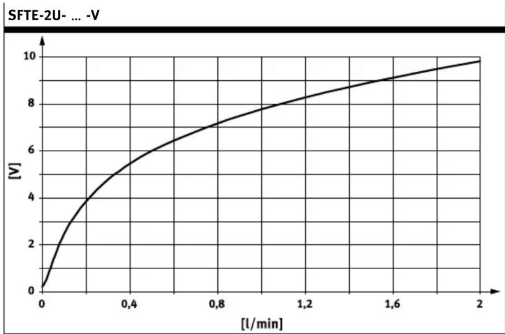
The following figures show the typical characteristic curve.

line
| [l/min] | [V] | | ------- | --- | | 0.0 | 1 | | 0.2 | 3 | | 0.4 | 4 | | 0.6 | 4.5 | | 0.8 | 4.8 | | 1.0 | 5 |Tab. 2

line
| [l/min] | [V] | | ------- | --- | | 0 | 1 | | 1 | 3 | | 2 | 4 | | 3 | 4.5 | | 4 | 4.8 | | 5 | 5 |Tab. 6

line
| [l/min] | V | | ------- | ----- | | 0.0 | 0.0 | | 0.2 | 5.0 | | 0.4 | 7.0 | | 0.6 | 8.0 | | 0.8 | 9.0 | | 1.0 | 10.0 |Tab. 3

line
| [l/min] | [V] | | ------- | --- | | 0 | 0 | | 1 | 4 | | 2 | 7 | | 3 | 8.5 | | 4 | 9.5 | | 5 | 10 |Tab. 7

line
| [l/min] | V | | ------- | --- | | 0 | 1 | | 0.4 | 3 | | 0.8 | 4 | | 1.2 | 4.5 | | 1.6 | 4.8 | | 2 | 5 |Tab. 4

line
| [l/min] | [V] | | ------- | --- | | 0 | 1 | | 2 | 3 | | 4 | 4 | | 6 | 4.5 | | 8 | 4.8 | | 10 | 5 |Tab. 8
line
| [l/min] | [V] | | ------- | --- | | 0.0 | 0 | | 0.4 | 5 | | 0.8 | 7 | | 1.2 | 8 | | 1.6 | 9 | | 2.0 | 10 |Tab. 5

line
| [l/min] | [V] | | ------- | --- | | 0 | 0 | | 2 | 6 | | 4 | 7 | | 6 | 8 | | 8 | 9 | | 10 | 10 |Tab. 9
6.2 Return flow characteristics
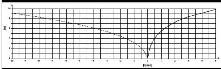
The STFE does not detect the flow direction. With a return flow, it issues a voltage signal with another characteristic curve, which is not calibrated.
Example SFTE-5U ... -V
line
| Time (l/min) | V | | :--- | :--- | | -10 | 9 | | -9 | 8.5 | | -8 | 8 | | -7 | 7.5 | | -6 | 7 | | -5 | 6.5 | | -4 | 6 | | -3 | 5.5 | | -2 | 4.5 | | -1 | 3.5 | | 0 | 0 | | 1 | 3.5 | | 2 | 5 | | 3 | 6.5 | | 4 | 8 | | 5 | 9 |Tab. 10
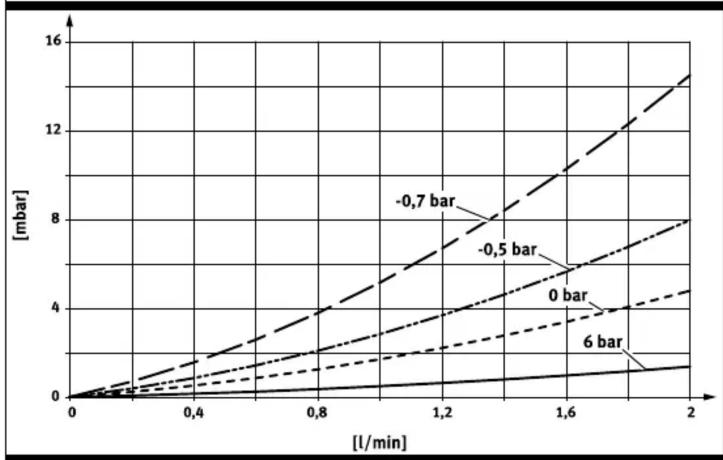
6.3 Pressure drop characteristics
SFTE-1U-Q4 | SFTE-2U-Q4
line
| [l/min] | -0.7 bar (mbar) | -0.5 bar (mbar) | 0 bar (mbar) | 6 bar (mbar) | |---|---|---|---|---| | 0.0 | 0.0 | 0.0 | 0.0 | 0.0 | | 0.4 | ~1.5 | ~1.2 | ~0.8 | ~0.6 | | 0.8 | ~3.5 | ~2.8 | ~1.8 | ~1.2 | | 1.2 | ~6.0 | ~4.8 | ~3.2 | ~2.2 | | 1.6 | ~9.5 | ~7.2 | ~4.8 | ~3.2 | | 2.0 | ~13.5 | ~10.5 | ~6.8 | ~4.2 |Tab. 11
SFTE-5U-Q4 | SFTE-10U-Q4

line
| Time [l/min] | Bar Value [-0.7 bar] [mbar] | Bar Value [-0.5 bar] [mbar] | Bar Value [0 bar] [mbar] | Bar Value [6 bar] [mbar] | |---|---|---|---|---| | 0 | 0 | 0 | 0 | 0 | | 2 | ~15 | ~10 | ~5 | ~2 | | 4 | ~35 | ~25 | ~15 | ~5 | | 6 | ~65 | ~45 | ~30 | ~10 | | 8 | ~95 | ~65 | ~45 | ~15 | | 10 | ~125 | ~85 | ~60 | ~20 |Tab. 12
7 Installation
Work on the product should only be conducted by qualified personnel.
7.1 Mechanical installation
i
Screws and nuts are not included in the scope of delivery.
Plate mounting
Screws in accordance with ISO 4017-M3 Torque: 0.5 Nm
Distance between holes: 27 ... 35 mm
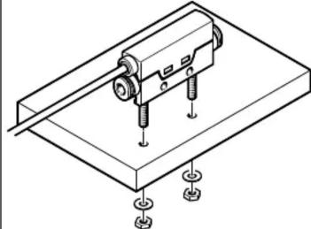
natural_image
Isometric technical diagram of a mechanical assembly with mounting holes and a central component (no text or symbols)Single bracket mounting
Screws: M3x14
Nuts: M3

natural_image
Technical line drawing of a mechanical sensor or connector assembly (no text or symbols)Side plate mounting
Screws M3
Torque: 0.5 Nm
Distance between holes: 14 mm
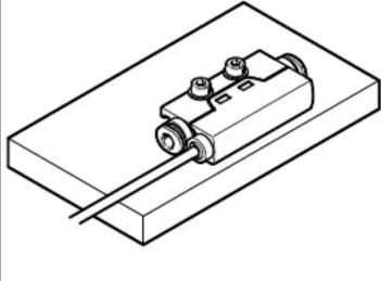
natural_image
Isometric line drawing of a mechanical assembly with a cylindrical component mounted on a rectangular base (no text or symbols)Multiple bracket mounting
Screws:
2-fold: M3x25
3-fold: M3x35
4-fold: M3x45
etc.
Nuts: M3

natural_image
Isometric line drawing of a mechanical or electronic component with three wheels and mounting base (no text or symbols)Tab. 13
7.2 Pneumatic installation
The direction of flow is indicated on the sensor by an arrow.
- Attach both tubings to the connections. Screw on M5F with max. 1.5 Nm.
i
If the tubing of the SFTE is incorrectly connected, flow rate values are also detected and issued by the analogue output. The voltage values in the negative flow direction are not the same as the voltage values in the positive flow direction
→ 6.2 Return flow characteristics.
7.3 Electrical installation
WARNING!
Risk of injury due to electric shock.
- For the electric power supply, use only PELV circuits that ensure a reliable electric disconnection from the mains network.
- Observe IEC 60204-1/EN 60204-1.
i
Long signal lines reduce the resistance to interference.
- Adhere to the maximum permissible cable length of 30m .
| Connection -0.3M8 Pin | Function | Wire colour -2.5K- | 1) |
| 41 + + 3 | 1 Operating | voltage +24 V Brown (BN) | |
| 3 0 V Blue (BU) | |||
| 4 Analogue | output Black (BK) | ||
1) Colours also apply for connecting cables NEBU-M8 ...
Tab. 14
Circuit diagrams
| SFTE- ... -2.5K SFTE- ... -0.3M8 | ||
| q U BN BK RL BU 0V | q u 1 4 3 → → → → → → → → → → → → → → → → → → → → → → → → → → → → → → → → → → → → → → → → → → → → → → → → → → +24V | q u BN BK RL BU 0V |
Tab. 15
8 Commissioning
- Switch on the operating voltage. Take the standby time and the warm-up period into account 12 Technical data.
9 Service and care
- Turn off energy source and compressed air.
- Clean sensor with non-abrasive cleaning agents.
10 Disassembly
- Turn off energy source and compressed air.
- Separate connections from the sensor.
- Loosen the mountings.
11 Fault clearance
| Fault description Cause Remedy | ||
| No voltage or unexpected voltage at the analogue output | No operating voltage or impermissible operating voltage. | Switch on the operating voltage. Comply with permissible operating voltage range. |
| Connections are swapped (reverse polarity). | Wire in accordance with the circuit diagram. | |
| Wire break in the supply line Replace device. | ||
| Short circuit/overload at the analogue output | Eliminate short circuit/overload. | |
| Flow rate outside the specified range (overflow) | Eliminate the excess overflow. | |
| Pressure drop/failure Check the pneumatic connection. Eliminate pressure failure. | ||
| Operation with prohibited medium. | Replace device and only operate with a permitted medium. | |
| Device defective Replace device. | ||
Tab. 16
12 Technical data
| General | |
| Approvals RCM compliance mark | |
| CE marking (→ declaration of conformity) | in accordance with EU EMC Directive in accordance with EU RoHS Directive |
Tab. 17
| Input signal/measuring element -1U- -2U- -5U- -10U- | ||||
| Measured variable Volumetric flow rate, mass flow rate | ||||
| Flow direction Unidirectional | ||||
| Measuring principle Thermal | ||||
| Warm-up time [min] 3 | ||||
| Method of measurement Heat loss | ||||
| Flow rate detection range, starting value [l/min] 0 0 0 | 0 | |||
| Flow rate detection range, end value [l/min] 1 2 5 | 10 | |||
| Flow rate detection range, end value [g/min] | 1.293 | 2.586 | 6.47 | 12.93 |
| Flow standard DIN 1343 (0 °C; 1,01325 bar; 0 %RH) | ||||
| Operating pressure [bar] | -0.9 ... 10 | |||
| Maximum permissible overflow [l/min] 20 100 | ||||
| Operating medium Compressed air in accordance with ISO 8573-1:2010[6:4:4], nitrogen ^1) | ||||
| Temperature of medium [°C] 0 ... 50 | ||||
| Ambient temperature [°C] | 0 ... 50 | |||
| Nominal conditions, factory-calibrated | – Medium: compressed air– Operating pressure: 0 bar– Room temperature: 20 ... 25 °C | |||
1) The use of inert gases is also possible. In this case, however, the characteristic curve and the detection range change.
Tab. 18
| Analogue output | -V- | -B- | |
| Analogue output | [V] | 0 ... 10 | 1 ... 5 |
| Rise time | [ms] 3 | ||
| Min. load resistance of voltage output | [kOhm] | 20 | |
| Deviation from typical characteristic | [±%FS] 5 | ||
| [V] | ± 0.5 | ± 0.2 | |
| Repetition accuracy | [±%FS] 1 | ||
| [V] | ± 0.1 | ± 0.04 | |
| Temperature co-efficient zero point | [±%FS/ K] | Typical 0.15 | |
| Pressure influence zero point | [±%FS] Typically 2 (in pressure range -0.7...6 bar) | 1) | |
1) In pressure range -0,9 ... -0.7 bar and 6 ... 10 bar, a pressure influence zero point of typically ± 5 % FS can be expected.
Tab. 19
| Output, additional data | |
| Short circuit protection | Yes |
| Overload protection | Available |
Tab. 20
| Electronics | ||
| Operating voltage range | [V DC] | 22 ... 26 |
| Idle current | [mA] | ≤ 17 mA (with 100 % flow rate) |
| Standby time ^1) | [ms] 25 | |
| Reverse polarity protection | For all electrical connections | |
1) The time required after switching on the supply voltage until the analogue output detects a stable defined status
Tab. 21
| Electromechanics | -0.3M8- | -2.5K- |
| Connection type | Plug connector | Cable |
| Connection technology | M8x1 A-coded in accordance with EN61076-2-104 | Open end |
| Number of pins/wires | 3 | |
| Max. connecting cable length [m] | 30 | |
Tab. 22
| Mechanics | -Q...- | -M5F- | |
| Mounting position | Any | ||
| Product weight without cable [g] | 12 | 9 | |
| Product weight with 0.3M8 [g] | 20 17 | ||
| Product weight with 2.5K [g] | 40 37 | ||
| Information on housing materials | Reinforced polyamide | ||
| Materials in contact with medium | – NBR– Reinforced polyamide– High-alloy stainless steel– Nickel-plated brass– Polyamide– Epoxy | – NBR– Reinforced polyamide– High-alloy stainless steel– Anodised wrought aluminium alloy– Polyamide– Epoxy | |
Tab. 23
| Immissions/emissions | -1U- | -1U- | -2U- | -2U- | -5U | -10U | |
| Storage temperature [°C] | -20 ... 80 | ||||||
| Degree of protection | IP40 | ||||||
| Pressure drop with 0 bar at [mbar] the output and qmax | [mbar] | 2 | 5 | 18 | 50 | ||
Tab. 24
- FESTO
- Further applicable documents
- Safety
- Intended use
- WARNING!
- Risk of injury from prohibited media.
- NOTICE!
- Product damage due to incorrect air quality class.
- General safety instructions
- Service
- Accessories
- Function
- Damage as a result of overflow.
- Characteristic curve
- Return flow characteristics
- Installation
- Mechanical installation
- Pneumatic installation
- Electrical installation
- Risk of injury due to electric shock.
- Commissioning
- Service and care
- Disassembly
Brand : Festo
Model : SFTE
Category : Flow detector