
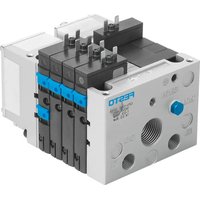
MS9-LF - Pneumatic valve Festo - Free user manual and instructions
Find the device manual for free MS9-LF Festo in PDF.


| Product Type | Pneumatic Service Unit (Filter-Lubricator) |
| Brand | Festo |
| Model | MS9-LF |
| Port Size | G3/8 |
| Operating Pressure | 0.5 – 10 bar |
| Maximum Pressure | 15 bar |
| Operating Temperature | -10 to 60 °C |
| Filter Filtration Grade | 5 µm |
| Lubricator Oil Reservoir Capacity | 0.1 L |
| Material (Bowl) | Polycarbonate |
| Material (Body) | Aluminum |
| Dimensions (W x H x D) | 60 mm x 180 mm x 120 mm |
| Weight | 0.5 kg |
| Flow Rate | 2000 L/min |
| Protection Class | IP65 |
| Condensate Drain | Manual |
| Maintenance | Periodic replacement of filter element and oil refill |
| Safety | Suitable for compressed air systems; do not exceed maximum pressure |
| Spare Parts Availability | Filter elements, seals, and bowls available from Festo |
| Reparability | Modular design allows easy replacement of components |
Frequently Asked Questions - MS9-LF Festo
User questions about MS9-LF Festo
0 question about this device. Answer the ones you know or ask your own.
Ask a new question about this device
Download the instructions for your Pneumatic valve in PDF format for free! Find your manual MS9-LF - Festo and take your electronic device back in hand. On this page are published all the documents necessary for the use of your device. MS9-LF by Festo.
USER MANUAL MS9-LF Festo
Operating instructions Original instructions
Fes to SE & Co. KG
Ruiter Straße 82
73734 Esslingen
Germany
+49 711 347-0
www.resto.com
806B012
1704d
[8068014]

For all available product documentation
→ www.festo.com/pk

Warning.
Products under pressure can cause injury to human beings and damage to properly.
- Before carrying out installation and maintenance work, switch off the compressed air supply.
- Use shut-off valves in the compressed air supply tubing for exhausting the system.

Note.
Fitting and commissioning to be carried out only by qualified personnel in accordance with the operating instructions.
This product is designed to be operated with compressed air only. The product is not suitable for use with other media (fluids or gases).
With controllers without secondary venting (only applies to MS9-...-OS): Due to the design of these controllers it can result in the output pressure p2 increasing to the maximum operating pressure p1 when there is no consumption at the output. When using a regulated device a small permissible internal leak without air consumption also leads to an increase in pressure at p2 and must be considered in the design phase,
MS9-...-G MS9-...-3/4/1

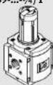

Fig. 2
Fig. 1


Fig. 4Fig. 3
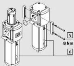
MS9-LR-...-PO

Fig. 6
Fig. 5


Fig. 10Fig. 8Fig

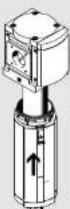

M59-LWS

9Nm
Fig. 13 Fig. 12 Fig. 114
1 Application
The filter regulator valve MS9-LFR and the pressure regulator MS9-LR are designed to regulate compressed air in the subsequent line to the set output pressure p2. The MS9-LFR/LR smoothes out fluctuations in pressure here. The output pressure p2 can be set within the pressure regulating range ( “Technical data” chapter) independently of the input pressure p1.
The filter regulator valve MS9-LFR and the filter MS9-LF with centrifugal separator remove dirt particles and condensate from the compressed air blown through it, while the water separator MS9-LWS removes condensal
2 Requirements for product use

Note.
Improper handling can result in malfunctions. Make sure that the following specifications are always observed:
• Compare the maximum values specified in these operating instructions with your actual application (e.g. operating media, pressures, temperatures, flow rates).
- Comply with the regulations of the trade association, the German Technical Control Board or relevant national regulations.
• Take into consideration the ambient conditions at the location of use.
- Remove all transport packing such as foils (polyamide), caps (polyethylene), cardboard boxes (except for the sealing elements of the pneumatic connections).
- Use the product in its original condition without any unauthorised modifications.
- Remove dirt particles in the supply lines by blowing out the tubing with compressed air. In this way you will pro...tect the device from premature failure or heavy wear (see DIN ISO 4414, section 9.4).
- Please observe the warnings and instructions – on the product
– in these operating instructions.
- Please ensure that there is a supply of correctly prepared compressed air.
3 Installation
3.1 Mechanical

Note.
Information about mounting module connectors, sub-bases and mounting brackets can be found in the operating instructions enclosed with the relevant accessories.
- Note the direction of flow from 1 to 2. The numbers [2] on the product housing serve as an orientation (→Fig. 2).
- Place the MS9-LFR/LF/LWS with sufficient space below the filter bowl (min. 150 mm).
- Adjust the MS9-LFR/LF/LWS standing vertically (± 5°). Direct mounting of an individual MS9-...- ^3/4 /1 with fastening screws
-
Press all protective caps 3 forwards out of the sub-base (→ Fig. 3). To do this, push a narrow object through the rear opening of the sub-base.
-
Fasten the individual device with four fastening screws 4 of size M6 and a minimum length of 90 mm
(→ Fig. 4). The distance between the holes is 90 mm in width and 66 mm in height.
Assembly with one or several already available service units of the same series ( Fig. 5)
- Dismantle the existing service unit string depending on the planned location of the device within the string. If the device is to be installed at the beginning or end of the service unit string:
- Disconnect the compressed air line from the service unit string or
- remove the sub-base from the service unit string. If the device is to be fitted between (two service units in the service unit string:
- Remove the module connector MS9-MV 5 between the two service units by loosening the screws.
- Mount the device in the desired location.
- Place the module connectors MS9-MV [5] in the grooves of the MS9-LFR/LR/LF/LWS and the adjoining service unit. There must be a seal between the service units
- Fasten the module connectors M59-MV with two screws.
- Fit the removed parts and devices from step 1 together into a service unit string again.
3.2 Pneumatic
If using screw connectors:
- Note the screw-in depth of the connecting thread.
Max. screw-in depth [mm]
| ISO 228 | NPT | ||
| M59....%/1: | 18.5 | M59....%/1: | 18.5 |
| M59....AGD/AGE/AGF: | 18.5 | M59....AQR/AQS/AQT: | 18.5 |
| M59....AGG/AGH: | 31.5 | M59....AQU/AQV: | 31.5 |
- Screw the connectors into the pneumatic connections using a suitable sealing material.
For MS9-LR-...-PO (→ Fig. 6):
- Screw the connector into the pneumatic connection 12 in the cover [7] using suitable sealing material. During installation make sure no dirt particles enter the device.
4 Commissioning
Setting the output pressure on the MS9-LFR/LR
- Pull the rotary knob upwards away from the housing (if necessary, remove padlock and push in the unlocking device 1 → Fig. 2).
2.Turn the rotary knob completely closed in the direction of “-”. - Pressurise your system slowly.
- Turn the rotary knob in the "+" direction until the desired pressure is displayed on the pressure gauge. The permissible output pressure (pressure regulation range → "Technical Data" chapter) must not be exceeded. Correctly pressurised, the operating pressure p1 is at least 0.5 bar higher than the output pressure p2.
- Press the rotary knob down to the housing. The button will then lock itself against unintentional turning.
If necessary: - Press the unlocking device 1 (→ Fig. 2) outwards. An existing padlock LRVS-D protects the unlocking device.
Setting the output pressure p2 with control pressure p12 (MS9-LR-...-PO only)
-
Pressurise your system slowly.
-
Use an external pressure regulator to pressurize the connection in the cover of the MS9-LR-...-PO with the required control pressure p12. Note that the control pressure must always be higher than the desired output pressure. The diagram (→ Technical data) shows the difference between control pressure p12 and output pressure p2.
5 Maintenance and care
Draining off the condensate
If the condensate level is at the mark 6 (→ Fig. 5):
| Manual outlet -M | Semi-automatic drainage -H | Fully-automatic drainage -V/-E... |
| Unscrow the outlet screw in an anti-clockwise direction (as seen from below). | Briefly exhaust the filter (p1 - 0 bar) or. | Filter/water separator empties automatically.Manual emptying:Unscrow the outlet screw in an anti-clockwise direction (V) (as seen from below).Press a button on the membrane keypad (E.)→ Condensate drain operating instructions. |
| Unscrow the outlet screw in an anti-clockwise direction (as seen from below). | ||
| The condensate will then flow out. | ||
| Barbed fitting connection for plastic tubing type PCN-6-NT already fitted. | QS connector for tubing type PUN-6/PAN-6 already fitted. | Barbed fitting connection for plastic tubing type PCN-6-NT already fitted. |
Replacing the filter cartridge for MS9-LFR/LF
- Replace the filter cartridge if the flow is reduced in spite of unmodified pressure setting.
- Exhaust the device,
- Push the unlocking slide [8] in the direction of the arrow (→ Fig. 7).
- Turn the filter bowl by hand or by the hexagon as far as possible in an anti-clockwise direction (as seen from below) until it is heard to strike the stop.
4.Pull the filter bowl away from the device (→ Fig. 8).
5.Turn the filter plate [9] in an anti-clockwise direction (→ Fig. 9). - Replace the filter cartridge if the pores are dirty (→ Fig. 10).
Hold the new filter cartridge only at the lower end. The filter cartridge has a cone shape and must be pushed into the carrier with the wider end first. - Place the new filter cartridge onto the filter plate and tighten it hand-light. (→ Fig. 11).
- Fit the individual parts together again in the reverse sequence. The following checks must then be made: - the locking pin of the filter bowl must face the large recess in the housing (→ Fig. 12).
- the unlocking slide must be heard to clip into place when the end stop is reached(→ Fig. 13).
-
Commission the system again.
-
Dispose of the used filter cartridge in compliance with the local waste disposal stipulations.
Cleaning the filter cup 10 for MS9-LWS
The filter cup must be cleaned in regular intervals if there are impurities in the condensate. The cleaning interval depends on the level of contamination of the compressed air used and the tubing system. Cleaning is required when the sight glass is full of condensate and it doesn't drain away. The filter cup, however, must be cleaned at least once a year.
- Drain the filter bowl if necessary by emptying it manually.
2.Exhaust the device.
3. Loosen the 4 mounting screws [11] on the bowl cover (→ Fig. 14).
- Remove the bowl cover with the filter cup 10 from the MS9-LWS. Make sure the O-ring 12 is not lost.
5.Hold the exterior of the filter cup under running water. Turn the filter cup when doing this. Use a soft brush to remove any hard deposits from the filter cup. Do not use any sharp objects as these can damage the filter. - Assemble the bowl cover and O-ring [12] to the MS9-LWS by using the 4 mounting screws [11].
- Commission the system again.
Cleaning the service unit
If the device is dirty, clean the exterior with a soft cloth. Permitted cleaning agents are soap suds (max. +60 °C) or petroleum ether (free of aromatic compounds).
6 Troubleshooting
| Malfunction | Possible cause | Remedy |
| Low flow | Filter cartridge is dirty | Replace filter cartridge (→ chapter "Maintenance and care") |
| Restriction between shut-off valve and service unit | Check tubing | |
| Pressure increases above the set operating pressure | Valve plate defective at scaling seat | Send device to Festa |
| Audible blow-off at the rotary knob | Valve seat damaged | Send device to Festa |
| Blowing can be heard at the outlet screw | Outlet screw leaks | Tighten or replace |
| Very little condensate flows during the emptying phase of the M59-LWS compared to when it was new. | Filter cup clogged with impurities | Clean the filter cup (→ chapter "Maintenance and care") |
| Signi glass is full of condensate but the condensate doesn't drain away |
7 Accessory
| Designation | Type | |
| Filter cartridge | 5 μm | MS9-LFP-C |
| 40 μm | MS9-LFP-E | |
8 Technical data
| Type | MS9- | |
| Operating pressure p1 [bar] | LFR-...M | 1.0 ... 20 |
| LF-...M | 0 ... 20 | |
| LFR/LF-...H | 1.5 ... 12 | |
| LFR/LF/LWS-...V | 2.0 ... 12 | |
| LFR/LF/LWS-...E1/E2/E3/E4 | 1.0 ... 16 | |
| LR | 1.0 ... 20 | |
| Pressure regulation range [bar] | LFR/LR-...D5 | 0.5 ... 4 |
| LFR/LR-...D6 | 0.5 ... 7 | |
| LFR/LR-...D7 | 0.5 ... 12 (0.5 ... 10) 1) | |
| LFR/LR-...D8 | 0.5 ... 16 | |
| LR-...P0 | 0.5 ... 16 | |
| Max. hysteresis [bar] | LFR/LR | 0.4 |
| Operating medium | Air quality class 5:7= as per DIN ISO 8:73-1 (filtered compressed air, lubricated or unlubilibrated, grade of Filtration 40 μm) 1) | |
| Mounting position | LFR/LF/LWS | Vertical ±5° |
| LR | Any | |
| Filtration grade [μm] | LFR/LF-...C | 5 |
| LFR/LF-...C | 40 | |
| Ambient temperature/ media temperature [°C] | LFR/LF-...M | 10 ... +60 (0 ... +50) 1) |
| LFR/LF/LWS-...H/V | +5 ... +60 (+5 ... +50) 1) | |
| LFR/LF/LWS-...E1/E2/E3/E4 | +1 ... +60 (+1 ... +50) 1) | |
| LR | 10 ... +60 (0 ... +50) 1) | |
| 1) Value in brackets with pressure sensor AD... | ||
Only applies to MS9-LR-...-PO:
Difference control pressure p12 - output pressure p2

line
| p12 [bar] | p12-p2 [bar] | | --------- | ------------ | | 0 | 0.55 | | 2 | 0.50 | | 4 | 0.45 | | 6 | 0.40 | | 8 | 0.38 | | 10 | 0.35 | | 12 | 0.32 | | 14 | 0.28 | | 16 | 0.25 |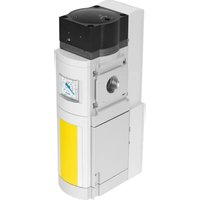


- Application
- Requirements for product use
- Installation
- Mechanical
- Assembly with one or several already available service units of the same series ( → Fig. 5)
- Pneumatic
- For MS9-LR-...-PO (→ Fig. 6):
- Commissioning
- Setting the output pressure on the MS9-LFR/LR
- Setting the output pressure p2 with control pressure p12 (MS9-LR-...-PO only)
- Maintenance and care
- Draining off the condensate
- Replacing the filter cartridge for MS9-LFR/LF
- Cleaning the filter cup 10 for MS9-LWS
- Cleaning the service unit
- Only applies to MS9-LR-...-PO:
Brand : Festo
Model : MS9-LF
Category : Pneumatic valve