
CNPS8900 Quiet - Computer Cooling Component ZALMAN - Free user manual and instructions
Find the device manual for free CNPS8900 Quiet ZALMAN in PDF.


| Product Type | CPU Cooler (Top-flow) |
| Brand | Zalman |
| Model | CNPS8900 Quiet |
| Compatible Socket | Intel LGA115x/1366/775, AMD AM2/AM2+/AM3/AM3+/FM1/FM2 |
| Dimensions (with fan) | 110 mm x 110 mm x 60 mm |
| Weight | 310 g |
| Fan Size | 92 mm |
| Fan Speed | 900 - 2000 RPM (PWM) |
| Noise Level | 18 - 30 dBA |
| Airflow | 45 CFM |
| Bearing Type | Rifle Bearing |
| Fan Connector | 4-pin PWM |
| Material | Aluminum fins with copper heatpipes |
| Color | Black and Blue |
| Power Consumption (Fan) | 1.2 W |
| Voltage | 12 V DC |
| Main Features | Low-profile design, quiet operation, PWM control |
| Maintenance | Clean with compressed air; avoid liquid cleaners |
| Safety | Ensure proper mounting to prevent damage |
| Spare Parts & Repairability | Fan replaceable; contact Zalman support |
| General Information | Designed for HTPC and small form factor builds |
Frequently Asked Questions - CNPS8900 Quiet ZALMAN
User questions about CNPS8900 Quiet ZALMAN
0 question about this device. Answer the ones you know or ask your own.
Ask a new question about this device
Download the instructions for your Computer Cooling Component in PDF format for free! Find your manual CNPS8900 Quiet - ZALMAN and take your electronic device back in hand. On this page are published all the documents necessary for the use of your device. CNPS8900 Quiet by ZALMAN.
USER MANUAL CNPS8900 Quiet ZALMAN
natural_image
Technical line drawing of a turbine or fan assembly (no text or symbols)Intel Socket 1366/1156/1155/1151/1150/775 CPUs
AMD Socket FM2/FM1/AM3+/AM3/AM2+/AM2 CPU&APUs
To ensure safe and easy installation, please read the following precautions.
www.ZALMAN.com
1. Precautions
1) Avoid inserting objects or hands into the fan while it is in operation to prevent product damage and injuries.
2) Do not ingest the Thermal Grease, and avoid its contact with skin and eyes. If contact is made with skin, wash off with water. If ingested or irritation persists, seek medical attention.
3) To prevent possible injuries, gloves must be worn while handling this product.
4) Excessive force exerted on the fan may cause damage to the fan and/or system.
5) Use and keep product away from reach of children.
6) Check the components list and condition of the product before installation. If any problem is found, contact the retailer to obtain a replacement.
7) During transportation of the system, the cooler must be removed. Zalman is not responsible for any damages that occur during the transport of a system.
8) Product design and specifications may be revised to improve quality and performance.
Disclaimer) Zalman Tech Co., Ltd. is not responsible for any damages due to external causes, including but not limited to, improper use, problems with electrical power, accident, neglect, alteration, repair, improper installation, or improper testing.
- Specifications
| Model Spec. | CNPS8900 Extreme CNPS 8900 Quiet | ||
| Material Pure Copper and Aluminum | |||
| Weight 400g | |||
| Dimensions | 120(L) x 120(W) x 60(H)mm | ||
| Fan | Bearing 2 Ball-Bearing Long Life Bearing | ||
| RPM 1,250~2,800 rpm ± 10% 1,000~1,500 rpm ± 10% | |||
| Noise Level 19.5 ~ 35dBA ± 10% 19 ~ 25dBA ± 10% | |||
| Input Voltage | 12V | ||
3. Installation Requirements
1) Space Requirements
The cooler's installation requires an unobstructed space of 120mm(width), 120mm(length), and 60mm(height), with the CPU as a central reference point. Please check if components such as ODDs and PSU protrude into the required space.

4.Components
-1) Common Components

natural_image
Technical line drawing of a mechanical fan or turbine assembly (no text or symbols)Cooler

natural_image
Technical line drawing of a mechanical component with symmetrical arms and central square (no text or symbols)Backplate

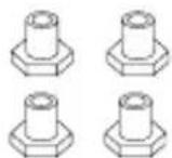

User's ManualNutsSide Ca

natural_image
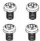
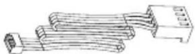
Technical line drawing of a coiled electrical connector (no text or symbols)Bolts (Cooler) Bolts (Clip) Extension Fan Cable
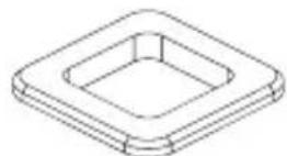

Loading Block Double-sided Tape

Thermal Grease (ZM-STG2M)
2) Intel Components 3) AMD Components
natural_image
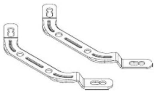
Technical line drawing of two mechanical brackets with mounting holes and side notches (no text or symbols)Intel Clip (Socket 1366/1156/1155/1150/1151/775)

natural_image
Technical line drawing of two mechanical bracket components (no text or symbols)AMD Clip (Socket FM2/FM1/AM3+/AM3/AM2+/AM2)

5. Installation

Common
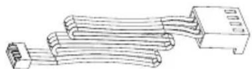
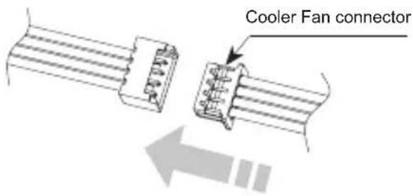
Connect the extension fan cable to the fan connector of cooler.
natural_image
Technical line drawing of a multi-core electrical connector (no text or symbols)Extension Fan Cable
A. Intel Socket 1366/1156/1155/1151/1150/775 Installation
① Install the Intel clip to the base of cooler using the bolts (Clip). Please make sure to put the curved part of clip toward the base as shown in the image.

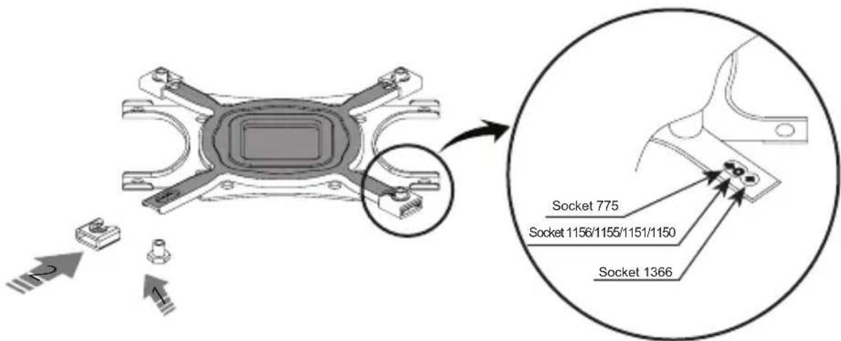
② Install the side cap to the Backplate according to a socket type.
Caution
Please note the orientation of the Nuts and the Side Caps.

natural_image
Technical line drawings of mechanical components including a housing, bracket, and pin (no text or symbols)
natural_image
Technical line drawing of three mechanical components: a housing, a bracket, and a bolt (no text or symbols)③ Socket 1366/1156/1155/1151/1150 Installation
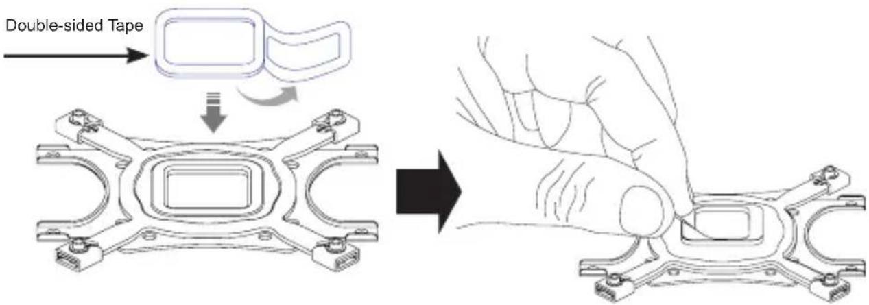
Attach Double-sided Tape to the center of the Backplate and remove the Double-sided Tape's Cover.
※ Installation of Socket 1366/1156/1155/1151/1150 does not require the Loading Block.
④ Socket 775 Installation
Remove the Sticker Cover from the Lower Tier of the Loading Block and attach to the Backplate.
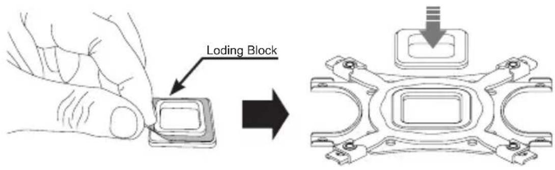
Attach Double-sided Tape to the Loading Block and remove the Double-sided Tape Cover.

Caution
Please note of the orientation of the Loading Block's Installation.

natural_image
Diagram showing two mechanical or electrical components with no visible text, numbers, or symbols.⑤ Align the Backplate's holes with motherboard's clip support holes, attach it to the back side of the motherboard.

natural_image
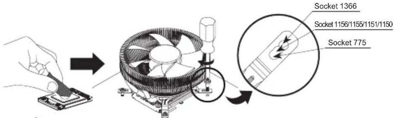
Technical diagram of a microchip assembly with mounting holes and a circular component base (no text or symbols)⑥ Spread the Thermal Grease on the CPU's surface and put the Cooler on the center of CPU and then fasten the Bolts (Cooler) to install the Cooler.
Caution
In the case of Tower Enclosure, the direction of heatpipe to be horizontally as shown in the image. The vertical installation can affect the performance of heat dissipation.

natural_image
Technical diagram of a mechanical assembly with components and cross-sections (no visible text or labels)
natural_image
Technical diagram of mechanical components and assembly (no visible text or labels)⑦ Connect the cooler's 4-pin connector to the motherboard's CPU Fan header.

Caution
Please make sure that PWM Control Mode is activated in the motherboard's BIOS settings.
B. AMD Socket FM2/FM1/AM3+/AM3/AM2+/AM2 Installation
① Install the AMD Clip to the base of cooler using the bolts (Clip).
Please make sure to put the curved part of clip toward the base as shown in the image.

② Install the side cap to the Backplate.

natural_image
Technical diagram of a mechanical component with mounting holes and internal cavity, showing directional arrows and dimension lines (no text or symbols)
Caution
Please note of the orientation of Nuts and side Caps.

natural_image
Technical line drawing of mechanical components including a bracket, washer, and nut (no text or symbols)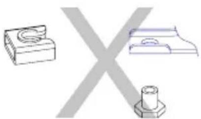
natural_image
Three technical drawings of mechanical parts: a cylindrical component, a flat plate with a circular hole, and a hexagonal base (no text or symbols)③ Remove the Sticker Cover from the Lower Tier of the Loading Block and attach to the Backplate.

Attach Double-sided Tape to the Loading Block and remove the Double-sided Tape Cover
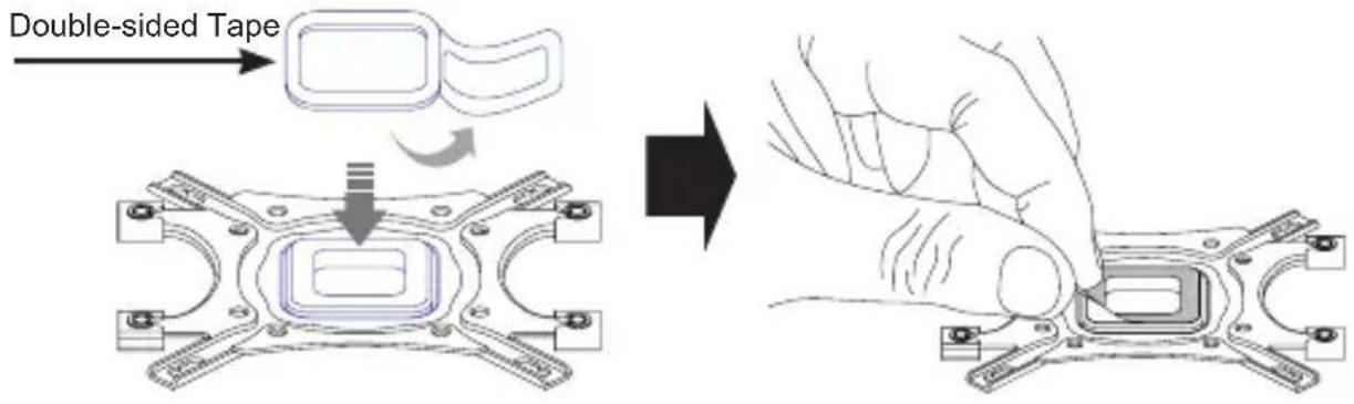
Caution
Please note of the orientation of the Loading Block's Installation.

natural_image
Diagram showing two mechanical components: a circular component with a horizontal bar and a cross-shaped component, connected by a line (no text or symbols present)④ Take away the fixed Clip support from the motherboard.

⑤ Align the Backplate's holes with motherboard's clip support holes, attach it to the back side of the motherboard.

⑥ Spread the Thermal Grease on the CPU's surface and put the Cooler on the center of CPU and then fasten the Bolts (Cooler) to install the Cooler.

natural_image
Diagram showing a hand using a screwdriver to press a CPU socket on a base, then adding a fan component (no text or symbols present)⑦ Connect the cooler's 4-pin connector to the motherboard's CPU Fan header.
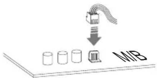
Caution
Please make sure that PWM Control Mode is activated in the motherboard's BIOS settings.


Brand : ZALMAN
Model : CNPS8900 Quiet
Category : Computer Cooling Component