XMP300BT GEN2 - Receiver OSD Audio - Free user manual and instructions
Find the device manual for free XMP300BT GEN2 OSD Audio in PDF.


| Product Type | Bluetooth Receiver / Amplifier |
| Brand | OSD Audio |
| Model | XMP300BT GEN2 |
| Power Output | 300W (peak) |
| Bluetooth Version | 5.0 |
| Wireless Range | Up to 50 feet (line of sight) |
| Audio Inputs | 3.5mm Aux, RCA, Bluetooth |
| Audio Outputs | Speaker terminals (up to 4 ohms) |
| Frequency Response | 20Hz - 20kHz |
| Signal-to-Noise Ratio | > 85 dB |
| Total Harmonic Distortion | TBD |
| Power Supply | AC 100-240V, 50/60Hz |
| Dimensions (W x H x D) | 17 x 5 x 12 inches (approx.) |
| Weight | 10 lbs (approx.) |
| Material | Metal chassis, plastic front panel |
| Mounting | Designed for rack or shelf mounting |
| Cooling | Passive ventilation slots |
| Remote Control | Included (IR) |
| Certifications | CE, FCC, RoHS |
| Warranty | 2 years limited |
| Cleaning Instructions | Wipe with a soft, dry cloth. Avoid liquids. |
Frequently Asked Questions - XMP300BT GEN2 OSD Audio
User questions about XMP300BT GEN2 OSD Audio
0 question about this device. Answer the ones you know or ask your own.
Ask a new question about this device
Download the instructions for your Receiver in PDF format for free! Find your manual XMP300BT GEN2 - OSD Audio and take your electronic device back in hand. On this page are published all the documents necessary for the use of your device. XMP300BT GEN2 by OSD Audio.
USER MANUAL XMP300BT GEN2 OSD Audio
CLASS D DUAL SOURCE POWER AMPLIFIER
Important Safety Instructions

The lightning flash with the arrowhead symbol within an equilateral triangle is intended to alert the user to the presence of dangerous voltage inside the product that may constitute a risk of electric shock.

The exclamation point within an equilateral triangle is intended to alert the user to the presence of important operating and maintenance instructions in the literature accompanying the product.
TO REDUCE THE RISK OF ELECTRIC SHOCK, DO NOT REMOVE COVER. NO USER-SERVICEABLE PARTS INSIDE. REFER SERVICING TO QUALIFIED SERVICE PERSONNEL
- Read Instructions — Read all the safety and operating instructions before operating this product.
- Retain Instructions — Retain safety and operating instructions for future reference.
- Heed Warnings — Adhere to all warnings on the product and in the operating instructions.
- Follow Instructions — Follow all operating and use instructions.
- Cleaning — Unplug this product from the wall outlet before cleaning. Use a damp cloth for cleaning. Clean the outside of the product only.
- Attachments — Do not use attachments that are not recommended by the product manufacturer; they may be hazardous.
- Water and Moisture — Do not use this product near water.
- Accessories — Do not place this product on an unstable cart or stand. The product may fall, causing bodily injury and damage to the product. A product and cart combination should be moved with care. Quick stops, excessive force, and uneven surfaces may cause the product and cart to overturn.
- Ventilation — Slots and openings in the cabinet are provided for ventilation to ensure reliable operation of the product and to protect it from overheating. These openings must not be blocked or covered. This product should not be placed in a built-in installation such as a bookcase or rack unless proper ventilation is provided.
- Power Sources — Operate this product only from the type of power source indicated on the label. If you are not sure of the type of power supply to your home, consult your dealer or local power company. This product is equipped with a three-prong grounding plug. This plug will only fit into a grounding power outlet. If you are unable to insert the plug into the outlet, contact your electrician to replace your obsolete outlet. Do not defeat the safety purpose of the grounding plug.
- Power Cord Protection — Power supply cords should be routed so that they are not likely to be walked on or pinched by items placed upon or against them.
- Lightning — Unplug the unit from the wall outlet for added protection during a lightning storm and when it is left unattended and unused for long periods of time. This will prevent damage to the product due to lightning and power line surges.
- Overloading — Do not overload wall outlets or extension cords. This can result in a fire or electric shock.
-
Inserting Objects into Unit — Never push objects of any kind into this product through any openings; they may touch dangerous voltage points or short out parts that could result in fire or electric shock.
-
Servicing — Do not attempt to repair or service this product yourself. Opening or removing covers may expose you to dangerous voltage and other hazards. Refer all servicing to qualified service personnel.
- Damage Requiring Service — Unplug this product from the wall outlet and refer servicing to qualified service personnel under the following conditions: a) If the power-supply cord or plug is damaged.
b) If liquid has been spilled into the product. c) If the product has been exposed to rain or water. d) If the product does not operate normally by following the operating instructions. e) If the product has been dropped or damaged in any way.
f) If the product exhibits a distinct change in performance. - Replacement Parts — When replacement parts are required, be sure the service technician has used replacement parts specified by the manufacturer. Unauthorized substitutions may result in fire, electric shock, and other hazards.
- Safety Check — Upon completion of any service or repairs to this product, ask the service technician to perform safety checks to determine that the product is in proper operating condition.
- Wall or Ceiling Mounting — Mount the product to a wall or ceiling only as recommended.
- Heat — The product should be situated away from heat sources such as radiators, heat registers, stoves, and other products (including amplifiers) that produce heat.
INTRO / FEATURES
Congratulations on your purchase of this product. Please take a few moments to read this entire manual, And be sure to retain this document for future reference. Please read and observe all safety instructions detailed. NOTE: If any part of this product is damaged or missing, please call your dealer. Please read your warranty and retain your receipt and original carton for possible future use.
• Automatic Source Switching Interrupt-Priority/Main
- Main Input with Main Output Pass thru
- Speaker A or B, A and B w/Front panel Switches'
- Front Panel Balance and Volume Controls
• Signal Sensing "Power On" and Trigger In/Out
- Rear Mounted Bass and Treble Controls
- Internal Wireless Source/ USB Music Playback
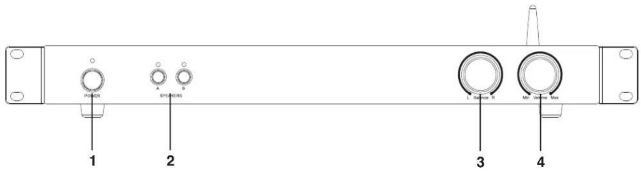
- Power Switch: (3-way LED: Green/Blue/Red) Power On (Green LED/Blue for Wireless) or OFF (no LED) LED changes to Red when in Standby after 7-9 minutes
-
Speaker Selector: Select Speaker A or Speaker B or Both at once
-
Balance: The Balance control lets you fade the amplifier's speaker output between the Right & Left channels.
- Volume: Controls Amplifier volume levels
-
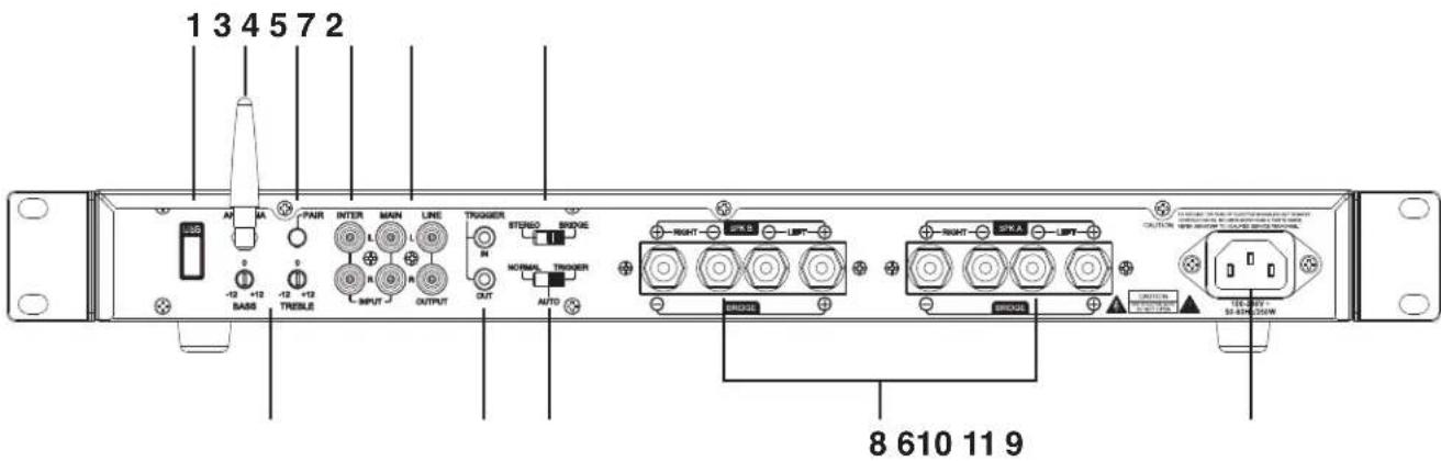
USB Input: Used to play U disk music. When the U disk storing MP3 music format is inserted into this USB socket, whether it is currently playing wireless music or music input by the main channel, it will automatically switch to the U disk music playback mode.
-
Antenna: This is a Wireless antenna, if this antenna is not installed, the receiving distance will be very short, or unable to connect wirelessly.
-
Pair Button: press & hold, when the blue power indicator starts to flash, then release, and the amplifier enters the state of searching for devices. If the connection to the device is successful, the power LED indicator will change from flashing to permanently on.
-
Inter Line Input: This is the secondary input, use MAIN IN or U disk music or wireless music for your main input. INTERRUPTING INPUT can be used if a second source is desired and takes over when signal is present and has at least a 5mV level. When there is no signal, or a signal with less than 5mV level, the amp switches back to MAIN IN or U disk music or wireless music after a brief delay.
-
Main Input/Output: MAIN IN should be used as the "primary" or main input for the amplifier Connect your receiver or main source to this input. Use LINE OUTPUT to pass MAIN IN or U disk music or wireless music signal to another.
-
Trigger In/Out: Allows this device to be powered on by other electronics or to power on other electronics via a 3.5mm mini phone plug cable.
-
Mode Select (Stereo or Bridged): Select Stereo mode for connecting one or two pair of loudspeakers, when set to Bridged mode, the amplifier becomes a single channel mono amplifier for powering one speaker. Only the Right audio input is used during bridged mode. Only one zone (A or B) can be bridged; not both.
-
Speaker Outputs: Speaker output terminals for zones A & B. Minimum impedance: 8 ohm bridged or 4 ohm stereo.
STEREO MODE
For stereo output connect the speaker's positive (red) terminal to the amplifier's positive (red) terminal, and the speaker's negative (black) terminal to the amplifier's negative (black) terminal for each Right and Left speaker.
BRIDGED MODE
Place the "MODE" switch in the "BRIDGED" position and use both red terminals to connect to the speaker. Connect the speaker's positive (red) terminal to the amplifier's red (+) terminal noted next to the bridging mark, and the speaker's negative (black) terminal to the amplifier's unmarked positive (red) terminal.
NOTE: This Amplifier produces significantly more power in bridged mode, Please refer to the spec chart and verify that your speakers power handling is rated accordingly to avoid possible damage!
-
AC Socket: This amplifier is configured for operation at 100-240V.
-
Bass & Treble : These controls can adjust bass and treble frequencies+/- 12dB at 100Hz and 10kHz.
-
Power Mode: Set the Auto On switch to Normal for manual power on/off. Set the Auto switch to Auto for signal sensing; the amp will turn on when audio signal (>5mV) is detected at the inputs The front-panel power switch must be in the On position (pushed in) for the Auto On feature to operate. Or, select 12V Trigger which allows the amp to be powered on by other electronic component or to power on other electronics via a 3.5 mini jack cable (between 3-20VDC).
Stereo Setup:
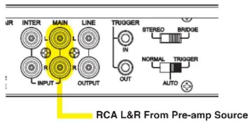
In this configuration, the mode switch is set to "Stereo". Connect the line out jacks from a stereo pre-amplifier or source to the MAIN input jacks of your XMP Gen2. Next connect your speakers to the terminals marked "Speaker A" observing proper polarity. Select the "A" speakers using the front panel zone selection buttons. Connect a second (optional) pair of speakers to the terminals marked "Speaker B". If you are connecting 4 speakers to the XMP Gen2 they must be 8-ohm speakers only. Press A and B together to use both zones.
Back Panel RCA Input/Outputs
Multiple Source Setup:
In the multiple source set up, a distributed audio system is connected to the XMP Gen2 as a local zone amplifier via the MAIN inputs. Normally the distributed audio system will be the audio source for the XMP Gen2. The distributed audio is then passed on to be used by additional zones or sub zones in the distributed system via the MAIN outputs.
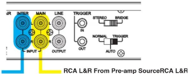
The audio output of a local source, such as an MP3 Player, CD, television, computer, etc., is connected to the XMP Gen2 via the INTERRUPTING inputs, and whenever the local source is active its signal will take priority over the distributed audio signal present at MAIN input. However, the distributed audio signal will still be present at the MAIN input. In this circumstance the audio output of the local source will be heard via the XMP Gen2. Once the local source is turned off or muted, the XMP Gen2 will automatically switch back to the distributed audio system as an audio source, assuming the local source remains inactive. There is a delay of up to 6 seconds when switching from INTERRUPTING input back to MAIN inputs.
Pairing:
The White Pairing Button for wireless is located on the Back Panels of the XMP100/300 Gen2. Press the White Button. See the Front Panel Power LED change from Solid Green to flashing Blue for Wireless Setup mode. Select XMP100 GEN2 or XMP300 GEN2 on the Wireless Enabled Device. If the connection is successful, The Power LED will change from Flashing to a steady Blue light while it is in pairing Mode. Once unpaired, the Power LED changes to a steady Green after about 2 minutes. Note: After 7-9 minutes of no signal input, the Power LED will change to a solid Red, also when the product is in a protection mode, it also displays a red light
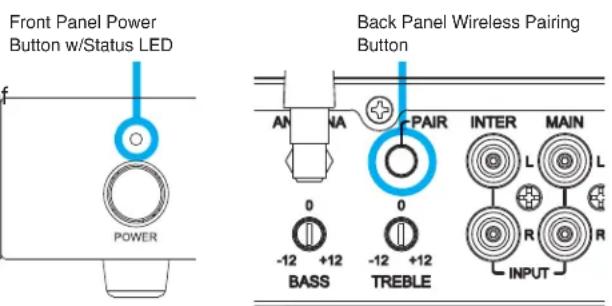
3-Way LED: Green for Power, Blue for Wireless setup and pairing. Red for Standby Mode after 7–9-minutes no signal
Model XMP100 Gen2 XMP300 Gen2
| Amplifier Type Stereo Four Channel (2A, 2B) Stereo Four Channel (2A, 2B) | ||
| Design Type Digital Class D Digital Class D | ||
| Wireless (version) V5.3 V5.3 | ||
| Rated Output Power 200 Watts Max 600 Watt Max | ||
| 8-Ohm Load 50W x 2 Channel RMS/Output 8-ohm | 150W x 2Chanel RMS/Output 8-ohm | |
| 4-Ohm Load 100W x 2 Channel RMS/Output 4-ohm | 300W x 2 Channel RMS/Output 4-ohm | |
| Bridged Mono | 200W X 1 Channel RMS (A or B)/Output 8Ω | 600W X 1 Channel (A or B)/Output 8Ω |
| Frequency Response | 20Hz - 20kHz | 20Hz - 20kHz |
| Impedance | 8-Ohm to 4-Ohm Stable | 8-Ohm to 4-Ohm Stable |
| Signal to Noise Ratio | 90≥dB 100W output into 4-ohms 20kHz20kHz Low-pass Filter | 90≥dB 300W output into 4-ohms 20kHz20kHz Low-pass Filter |
| Channel Separation | 50dB @1kHz referred to 50W Output into 8Ω | 50dB @1kHz referred to 150W Output into 8Ω |
| Input Sensitivity | 700mV Input rated 50W Output into 8Ω | 700mV Input rated 150W Output into 8Ω |
| Sources/Inputs | Wireless/USB/Line-In (Interrupt/Main) | Wireless/USB/Line-In (Interrupt/Main) |
| Output | Signal (low) level/Speaker (High) Level Outputs | Signal (low) level/Speaker (High) Level Outputs |
| THD | «1% @ output Rated power /« 0.07%@ output 1~80W | «1% @ output Rated power /« 0.07%@ output 1~240W |
| Bass and Treble Controls | (+/-) 12dB @ 100Hz and 10kHz | (+/-) 12dB @ 100Hz and 10kHz |
| Other Back Panel Controls | Trigger Functions/Bridged Mono-Stereo | Trigger Functions/Bridged Mono-Stereo |
| Front Panel Controls | Power/Speaker (A/B)/Balance/Volume | Power/Speaker (A/B)/Balance/Volume |
| AC Power | Multi-Voltage 100V-240V 50-60Hz/250V | Multi-Voltage 100V-240V 50-60Hz/250V |
| Dimensions | 430mm W x 44.0mm H x 159.4mm D16.92" W x 1.73" H x 6.27" D | 430mm W x 44.0mm H x 201.20mm D16.92" W x 1.73" H x 7.92" D |
| Net Weight | 2.4 KG/5.29 Pounds | 3.2 KG/7.05 Pounds |
OSD Audio electronics have (2) year Limited Warranty against defects in materials and workmanship. Proof of purchase must accompany all claims. During the warranty period OSD Audio will replace any defective part and correct any defect in workmanship without charge for either parts or labor.
OSD Audio may replace returned electronics with a product of equal value and performance. In such cases, some modifications to the mounting may be necessary and are not OSD Audio's responsibility.
For this warranty to apply, the unit must be installed and used according to its written instructions. If necessary, repairs must be performed by OSD Audio. The unit must be returned to OSD Audio at the owner's expense and with prior written permission. Accidental damage and shipping damage are not considered defects, nor is damaged resulting from abuse or from servicing performed by an agency or person not specifically authorized in writing by OSD Audio.
OSD Audio sells products only through authorized dealers and distributors to ensure that customers obtain proper support and service. Any OSD Audio product purchased from an unauthorized dealer or other source, including retailers, mail order dealers and online sellers will not be honored or serviced under existing OSD Audio warranty policy. Any sale of product by an unauthorized source or other manner not authorized by OSD Audio shall void the warranty on the applicable product.
Damage to or destruction of components due to application of excessive power voids the warranty on those parts. In these cases, repairs will be made on the basis of the retail value of the parts and labor. To return for repairs, you must email customer service at RMA@audiogeargroup.com for a Returned Merchandise Authorization (RMA) number then the unit must be shipped to OSD Audio at the owner's expense, along with a note explaining the nature of service required. Be sure to pack the product(s) in a corrugated container with at least 3 inches of resilient material to protect the unit from damage in transit.
This Warranty Does Not Cover: Damage caused by abuse, accident, misuse, negligence, or improper operation (installation) • Any products that have been altered or modified • Any product whose identifying number of decal, serial #, etc. has been altered, defaced or removed • Normal wear and maintenance.
Brand : OSD Audio
Model : XMP300BT GEN2
Category : Receiver