
NAV E 101 - Electronics Extron - Free user manual and instructions
Find the device manual for free NAV E 101 Extron in PDF.


| Product Type | Network AV Encoder |
| Brand | Extron |
| Model | NAV E 101 |
| Video Input | 1x HDMI |
| Video Output | 1x HDMI (loop-through) |
| Max Resolution | 1920x1200 @ 60 Hz |
| Audio Support | Embedded HDMI audio |
| Network Interface | 1x Gigabit Ethernet |
| Streaming Protocol | Extron PURE3 codec |
| Power Supply | External 12 VDC, 0.5 A |
| Power Consumption | 6 watts (typical) |
| Dimensions (H x W x D) | 1.0 x 4.3 x 3.0 inches (2.5 x 10.9 x 7.6 cm) |
| Weight | 0.5 lbs (0.23 kg) |
| Enclosure Type | Metal, half-rack width |
| Mounting | Desk or rack mountable (optional kit) |
| Operating Temperature | 32 to 122 °F (0 to 50 °C) |
| Certifications | CE, FCC Class A, UL |
| Warranty | 3 years parts and labor |
| Included Accessories | Power supply, setup guide |
| Maintenance | Keep vents clean; avoid moisture |
| Safety | Use only supplied power adapter; do not open |
Frequently Asked Questions - NAV E 101 Extron
User questions about NAV E 101 Extron
0 question about this device. Answer the ones you know or ask your own.
Ask a new question about this device
Download the instructions for your Electronics in PDF format for free! Find your manual NAV E 101 - Extron and take your electronic device back in hand. On this page are published all the documents necessary for the use of your device. NAV E 101 by Extron.
USER MANUAL NAV E 101 Extron
NAV E 501 and NAV E 101
Streaming HDMI Encoders
Safety Instructions
Safety Instructions • English

WARNING: This symbol, when used on the product, is intended to alert the user of the presence of uninsulated dangerous voltage within the product's enclosure that may present a risk of electric shock.
ATTENTION:
This symbol, ⚠️, when used on the product, is intended to f important operating and maintenance (servicing) instructions provided with the equipment.
For information on safety guidelines, regulatory compliances, EMI/EMF compatibility, accessibility, and related topics, see the Extron Safety and Regulatory Compliance Guide, part number 68-290-01, on the Extron website, www.extron.com.
All trademarks mentioned in this guide are the properties of their respective owners.
The following registered trademarks (*), registered service marks (SM), and trademarks (TM) are the property of RGB Systems, Inc. or Extron (see the current list of trademarks on the Terms of Use page at www.extron.com):
| Registered Trademarks ^® |
| Extron, Cable Cubby, ControlScript, CrossPoint, DTP, eBUS, EDID Manager, EDID Minder, eLink, Flat Field, FlexOS, Glitch Free, Global Configurator, Global Scripter, GlobalViewer, Hideaway, HyperLane, IP Intercom, IP Link, Key Minder, LinkLicense, LockIt, MediaLink, MediaPort, NAV, NetPA, PlenumVault, PoleVault, PowerCage, PURE3, Quantum, Sharelink, Show Me, SoundField, SpeedMount, SpeedSwitch, StudioStation, System INTEGRATOR, TeamWork, TouchLink, V-Lock, VN-Matrix, VoiceLift, WallVault, WindoWall, XPA, XTP, XTP Systems, and ZipClip |
| Registered Service Mark ^SM : S3 Service Support Solutions |
| Trademarks ^TM |
| AAP, AFL (Accu-RATE Frame Lock), ADSP (Advanced Digital Sync Processing), AVEdge, CableCover, CDRS (Class D Ripple Suppression), Codec Connect, DDSP (Digital Display Sync Processing), DMI (Dynamic Motion Interpolation), Driver Configurator, DSP Configurator, DSVP (Digital Sync Validation Processing), EQIP, Everlast, FastBite, Flex55, FOX, FOXBOX, IP Intercom HelpDesk, MAAP, MicroDigital, Opti-Torque, PendantConnect, ProDSP, QS-FPC (QuickSwitch Front Panel Controller), Room Agent, Scope-Trigger, SIS, Simple Instruction Set, Skew-Free, SpeedNav, Triple-Action Switching, True4K, Vector ^TM 4K , WebShare, XTRA, and ZipCaddy |
FCC Class A Notice
This equipment has been tested and found to comply with the limits for a Class A digital device, pursuant to part 15 of the FCC rules. The Class A limits provide reasonable protection against harmful interference when the equipment is operated in a commercial environment. This equipment generates, uses, and can radiate radio frequency energy and, if not installed and used in accordance with the instruction manual, may cause harmful interference to radio communications. Operation of this equipment in a residential area is likely to cause interference. This interference must be corrected at the expense of the user.
NOTES:
- This unit was tested with shielded I/O cables on the peripheral devices. Shielded cables must be used to ensure compliance with FCC emissions limits.
- For more information on safety guidelines, regulatory compliances, EMI/EMF compatibility, accessibility, and related topics, see the Extron Safety and Regulatory Compliance Guide on the Extron website.
Battery
CAUTION: Risk of explosion — Do not replace the battery with an incorrect type. Dispose of used batteries according to the instructions.
Conventions Used in this Guide
Notifications
The following notifications are used in this guide:
CAUTION: Risk of minor personal injury.
NOTE: A note draws attention to important information.
TIP: A tip provides a suggestion to make working with the application easier.
Software Commands
Commands are written in the fonts shown here:
^AR Merge Scene,,0p1 scene 1,1^B 51^W^C.0
[01]R 000400300 00400 0080000600 [02]35 [17] [03]
Esc X1 *X19 *X23 *X26 *X25 CE←
NOTE: For commands and examples of computer or device responses used in this guide, the character “o” is the number zero and “O” is the capital letter “o.”
Computer responses and directory paths that do not have variables are written in the font shown here:
Reply from 208.132.180.48: bytes=32 times=2ms TTL=32
C:\Program Files\Extron
Variables are written in slanted form as shown here:
ping xxx.xxx.xxx.xxx -t
SOH R Data STX Command ETB ETX
Selectable items, such as menu names, menu options, buttons, tabs, and field names are written in the font shown here:
From the File menu, select New.
Click the OK button.
Specifications Availability
Product specifications are available on the Extron website, www.extron.com.
Extron Glossary of Terms
A glossary of terms is available at www.extron.com/technology/glossary.aspx.
Contents
Introduction ...... 1
About this Guide....1
About the NAV System....1
About the Encoder ....1
About the Decoder 2
System Interaction and Capabilities .....2
Features....3
Installation and Basic Operation .... 5
Mounting....5
Rear Panel Connections and Features....5
Connector and Cable Details 7
Front Panel Features....11
Startup and Basic Operation ....13
Power....13
Pairing Devices Manually 13
Operation 14
HTML Operation....16
Opening the Embedded HTML Pages ......16
Using the HTML Pages....19
Input Configuration Page 20
Output Configuration Page 23
Ties Page 33
Tools Pages 34
Monitoring Page 42
Settings Pages 47
About Page 64
Control System...... 65
Secure Platform Device 65
Toolbelt....65
Global Configurator Plus and Professional ......67
Global Scripter....68
SIS Operation 69
Host-to-Encoder Communications ....69
Encoder-Initiated Messages....69
Encoder Error Responses....70
Using the Command and Response Tables .....70
Common symbol definitions....70
SIS Command and Response Tables....71
Troubleshooting 75
Alarms....75
Reference Information 78
Mounting the Encoder 78
Tabletop Use 78
Mounting kits....78
Download a Firmware or Software Package .....79
UL Rack-Mounting Guidelines ....79
Introduction
This section contains the following topics:
- About this Guide
• About the NAV System - Features
About this Guide
This guide contains installation, configuration, and operating information for the following Extron streaming encoders:
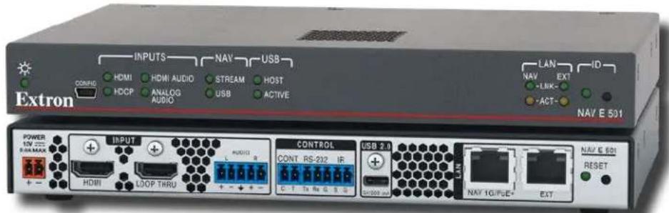
- NAV E 501 Encoder — Streams HDMI video and audio over a managed 1G IP network. Also supports USB and Ethernet extension.
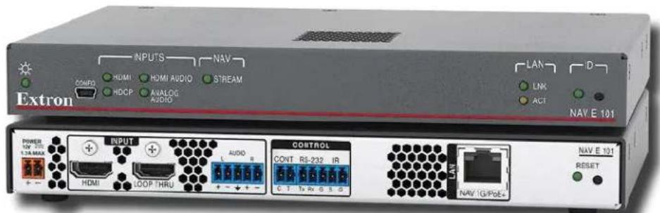
- NAV E 101 Encoder — Streams HDMI video and audio over a managed 1G IP network.
NOTE: In this guide:
- The NAV E 501 and NAV E 101 are both referred to as an “encoder.” They are referenced by model name when differences exist.
- NAV encoders and decoders collectively are referred to as "endpoints."
About the NAV System
The Extron NAV decoders and one or more compatible encoders form an AV distribution and switching matrix on an Internet Group Management Protocol (IGMP) Managed IP Network. The encoders are configured for low latency multicast streaming. The decoders are configured to join the assigned multicast group.
About the Encoder
A NAV encoder inputs an HDMI video signal and generates a video and audio stream that can be transmitted over an IP network using the Extron PURE3 Codec. The PURE3 Codec exceeds many of the performance characteristics of existing compression formats and provides exceptionally robust protection against network errors, making it ideal for quality-critical applications.
The data stream can include:
- HDCP-compliant HDMI video (which can include embedded digital audio [SMPTE 299M and SMPTE 272M-A]) at resolutions up to 4k @ 60 Hz
- Optional analog audio
• NAV E 501 only — USB 2.0 port control and data signals
• NAV E 501 only — An Ethernet Extension port allows communication to the same network
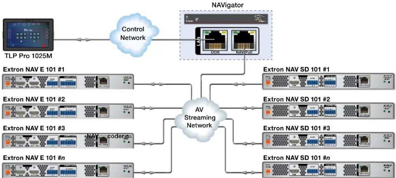
You can manage the endpoints using an Extron NAVigator System Manager (see figure 1). The base version of the NAVigator can control up to 16 endpoints. Available LinkLicense expansion options can accommodate up to 240 endpoints.
flowchart
graph TD
    A["TLP Pro 1025M"] --> B["Control Network"]
    B --> C["NAVigator"]
    C --> D["Extron NAV E 101 #1"]
    C --> E["Extron NAV SD 101 #1"]
    C --> F["Extron NAV E 101 #2"]
    C --> G["Extron NAV SD 101 #2"]
    C --> H["Extron NAV E 101 #3"]
    C --> I["Extron NAV SD 101 #3"]
    C --> J["Extron NAV E 101 #n"]
    C --> K["Extron NAV SD 101 #n"]
    D --> L["AV Streaming Network"]
    E --> L
    F --> L
    G --> L
    H --> L
    I --> L
    J --> L
    K --> L
Figure 1. Typical NAV Application
The streamed NAV signal is routed using a managed network switch and can be dedicated to a specific LAN. AV switching can be done via a control system by interfacing to the NAV decoder or the NAVigator.
NOTE: The RS-232 and IR communications are driven via a control system. The encoder and decoder do not generate or respond to the RS-232 and IR communication signals.
About the Decoder
One or more compatible decoders, such as the NAV SD 501 or NAV SD 101, decode the data stream back into the original video and audio signal formats and output them locally.
System Interaction and Capabilities
Each encoder and decoder has an integrated web interface. All normal system configuration and control is via the web interface of the NAVigator. Using a computer on the same network and a standard web browser; such as Google Chrome™, Mozilla™ Firefox™, or Microsoft® Edge™; you can configure any encoder or decoder unit in the system.
The embedded audio can be transported as a 2-channel LPCM uncompressed stream. Audio can follow video to the same decoder or be broken away to a different endpoint.
A dedicated RS-232/IR port, a secure platform device (SPD), is available for distributing RS-232 and IR data with the coded/ decoded video, such as for control of a projector. Tally and Contact Closure supports Extron Show Me Cables.
The units are housed in 1-inch high, half-rack width metal enclosures that can be mounted in any standard 19-inch rack or under furniture with optional mounting kits.
The external 100 VAC to 240 VAC, 50-60 Hz power supply provides worldwide power compatibility.
Features
- Encodes and streams video and audio over 1 Gbps Ethernet networks — Standard 1 Gbps Ethernet supports flexible system design and transmission over large distances to any location.
- Supports HDMI 2.0 at resolutions up to 4K/60 @ 4:4:4 — HDMI up to 4K @ 60 Hz (4096 x 2160) with full 4:4:4 chroma subsampling ensures accurate reproduction of source images.
- PURE3 Codec — Patented by Extron, the wavelet-based compression technology delivers high image quality with very low-latency at highly efficient bit rates. With its high immunity to network errors and built-in error concealment, PURE3 facilitates reliable, real-time delivery of visually lossless video over IP networks.
- PURE3 Intelligent Selective Streaming (ISS) — Leverages low motion content to achieve extremely low bitrates while maintaining visually lossless performance.
- Interoperable with 10 Gbps NAV endpoints — 1 Gbps video can be readily decoded by 10 Gbps decoders for greater compatibility in mixed 1 Gbps/10 Gbps solutions.
- Ultra-low latency with high quality video — Streams professional-grade video with ultra-low latency using the unique wavelet-based Extron PURE3 codec, guaranteeing exceptional user experience and accurate reproduction of every detail.
- AES67 audio support — Supports the AES67 audio over IP standard, providing compatibility with Extron and third-party DSP processors.
- HDCP 2.3 compliant — Ensures display of content-protected media and interoperability with other HDCP-compliant devices.
- (NAV E 501 only) USB 2.0 extension — Built-in USB 2.0 extension facilitates connection to peripheral USB devices over the same cable as video and audio. Ideal for KVM applications or remote connectivity for USB cameras or storage devices.
- (NAV E 501 only) Ethernet expansion — Built-in Ethernet expansion facilitates connection to peripheral Ethernet-enabled devices over the same cable as video and audio. Saves on cabling cost in installations with any remote devices requiring LAN connectivity.
- PoE+ compatibility eliminates the need for a local power supply — PoE+ enables receipt of power directly from the PoE switch, eliminating the need for bulky local power supplies.
- SRTP stream encryption (SRTP) — Ensures encryption, message authentication, and data integrity for video and data streams.
- Audio breakaway enables independent audio and video switching — Provides the capability to break away an audio signal from its corresponding video signal.
- Customizable Screen Saver — Displays a user-supplied custom image, black screen, blue screen, or the last video frame when no active video signal or stream is present.
- Priority Routing — Assign custom tags to endpoints using built-in NAVigator HTML pages. Tags can be used to further classify endpoints, easily locate them on the network, or apply rules for routing with an Extron control system.
- 802.1X port-based Network Access Control — Supports 802.1X port-based authentication, requiring that all devices are approved before network access is granted.
- Certified FIPS 140-2 module — Extron cryptographic module meets NIST and CCS guidelines and is certified by CMVP to the FIPS 140-2 information processing standard in order to ensure protection of sensitive data.
- Active Directory support — Integrates with Microsoft Active Directory, simplifying user management, group authentication, and helping to maintain strong security policies.
- Adjustable bit rate — Selects bit rates while maintaining image quality for a more flexible network configuration that easily adapts to different application requirements. A non-blocking solution is available to accommodate even very large installations.
- Error concealment — Offers high immunity to network errors, ensuring reliable transmission of high quality imagery with the ability to conceal errors even during incidents of heavy packet loss.
- HDMI loop-through — Local HDMI output provides signal for a local display, an AV system, or a hardware codec, enabling monitoring or sharing of content without the need for a separate distribution amplifier.
- Embedded web interface — Intuitive, user-friendly embedded web interface simplifies device configuration, setup, and system operation.
- EDID Minder automatically manages EDID communication between connected devices — EDID Minder ensures that all sources power up properly and reliably output content for display.
- Key Minder continuously verifies HDCP compliance for quick, reliable switching — Key Minder authenticates and maintains continuous HDCP encryption between input and output devices to ensure quick and reliable switching in professional AV environments, while enabling simultaneous distribution of a single source signal to one or more displays.
- HDCP Visual Confirmation — When HDCP-encrypted content is transmitted to a non-HDCP compliant display, a full-screen green signal is sent to the display for immediate visual confirmation that protected content cannot be viewed on that display.
- Supports analog and embedded HDMI audio signals — Directly interfaces with common AV source signals for compatibility with most audio devices.
- Compatible with Show Me cables — Show Me cables and retractors provide convenient connectivity, user input selection, and control of AV systems.
- Integrates with Pro Series control systems for secure, user-friendly external control — Designed to integrate directly with Extron Pro Series control systems for secure, encrypted RS-232 and IR control of external devices without the need for additional control processors.
- Consumer Electronics Control (CEC) capability — CEC commands can be triggered to control displays or other AV devices connected over HDMI.
- Secure Platform Interface — Working natively with NAV Systems, Extron Pro Series control systems offer flexible system management and matrix switching control via a Secure Platform Interface that encrypts all commands from control processor to endpoint. Together, NAV and Extron Pro Series control systems create the most secure and reliable Pro AV over IP solution on the market.
- Multicast filtering with IGMPv3 — Supports multicast filtering with IGMPv3 for lower bandwidth consumption. Enables use of standard network equipment.
- One-button endpoint identification — Identify endpoints with an ID button and indicator for quick discovery of units on a network, simplifying diagnostics and installation.
- External Extron Everlast power supply included — Provides worldwide power compatibility with high-demonstrated reliability and low power consumption.
• Extron Everlast Power Supply is covered by a 7-year parts and labor warranty.
- 1-inch (2.5 cm) high, half rack width metal enclosure — Compact, low profile enclosure for discreet placement and concealment.
- ZipClip 400 included — Enables quick and secure mounting to rack rails, tables, shelves, and lecterns.
Installation and Basic Operation
This section describes the installation and the operation of the NAV E 501 and NAV E 101 encoders, including:
- Mounting
• Rear Panel Connections and Features
• Front Panel Connection and Indicators
• Startup and Basic Operation
Mounting
If desired, mount the encoder in a rack (see Mounting the Encoder on page 78).
Rear Panel Connections and Features
flowchart
graph TD
    subgraph Power
        A["POWER 12V 2.0 A MAX"] --> B["INPUT"]
        B --> C["HDMI LOOP THRU"]
        C --> D["AUDIO L CONT"]
        D --> E["CONTROL"]
        E --> F["CONT RS-232 IR"]
        F --> G["USB 2.0 5V/500 mA"]
        G --> H["LAN NAV 1G/PoE+ EXT"]
        H --> I["NAV E 501 RESET"]
    end
    subgraph Control
        J["POWER 12V 1.7 A MAX"] --> K["INPUT"]
        K --> L["HDMI LOOP THRU"]
        L --> M["AUDIO L CONT"]
        M --> N["CONTROL"]
        N --> O["RS-232 IRR"]
        O --> P["CONTROL"]
        P --> Q["CONT RS-232 IR"]
        Q --> R["USB 2.0 5V/500 mA"]
        R --> S["LAN NAV 1G/PoE+"]
        S --> T["NAV E 101 RESET"]
    end
    subgraph Network
        U["POWER 12V 2.0 A MAX"] --> V["INPUT"]
        V --> W["HDMI LOOP THRU"]
        W --> X["AUDIO L CONT"]
        X --> Y["CONTROL"]
        Y --> Z["RS-232 IRR"]
        Z --> AA["CONTROL"]
        AA --> AB["CONT RS-232 IR"]
        AB --> AC["USB 2.0 5V/500 mA"]
        AC --> AD["LAN NAV 1G/PoE+"]
        AD --> AE["NAV E 501 RESET"]
    end
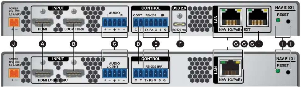
Figure 2. NAV E 501 and NAV E 101 Rear Panel Connectors and Features
A HDMI input port
USB 2.0 port (NAV E 501 only)
B LOOP THRU port
G NAV 1G/PoE+ port
© AUDIO input port
H Extension port (NAV E 501 only)
CONTROL Contact Closure port
1 RESET button and LED
E CONTROL RS-232/IR port
Power connector
A HDMI input port — Connect an HDMI cable between this port and the HDMI output port (or DVI port, with an appropriate adapter) of the digital video source (see LockIt Lacing Brackets on page 7 to use the LockIt HDMI Cable Lacing Bracket to secure the connector to the encoder).
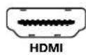
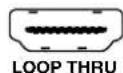
B LOOP THRU port — Connect a display to this female HDMI connector for local loop-through monitoring of the source signal (see LockIt Lacing Brackets).
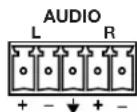
Audio input port (see page 5) — Connect balanced or unbalanced stereo audio input to this 5-pole, 3.5 mm captive screw connector (see Analog audio connectors on page 8 to wire the connector).
CONTROL Contact Closure port — Connect an Extron Show Me cable to the port to allow an Extron Teamwork 400 user to request to take over the presentation from this encoder (see the Teamwork 400 User Guide, available at www.extron.com).
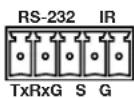
E CONTROL RS-232/IR port — Connect a serial RS-232 signal, a modulated IR signal, or both to this 3.5 mm, 5-pole captive screw connector for bidirectional RS-232 and IR communication (see Control connector wiring on page 8 to wire the connector).
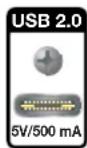
USB 2.0 port (NAV E 501 only) — Connect a USB Type-O® cable from a USB host or a USB device (see LockIt Lacing Brackets on page 7 to securely fasten the USB connector to the encoder).
NOTE: This connector is limited to supplying 500 mA in USB device mode.

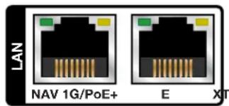
G NAV 1G/PoE+ port — Connect to an Ethernet LAN on which one or more decoders also reside for streaming, control, and PoE+.
Extension port (NAV E 501 only) — If desired, connect another networked device to this port. The port acts as a networked switch to the NAV 1G/PoE+ port (G).
NOTES:
- See TP cable termination on page 9 to properly wire the RJ-45 connectors G and H.
-
The Extension port (H) cannot provide PoE.
• RJ-45 port LEDs for both ports indicate as follows: -
Act (amber) LED — Indicates transmission of data packets on the RJ-45 connector. This LED blinks as the encoder communicates.
- Link (green) LED — Indicates that the encoder is properly connected to an Ethernet LAN. This LED lights steadily.
RESET button and LED — The RESET button initiates three levels of encoder reset. For the different reset levels, press and hold the button while the encoder is running or while you power up the encoder (see Reset Operations on page 14 for details).
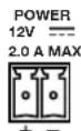
Power connector — Plug the included external 12 VDC power supply into this 2-pole connector to power the encoder locally.
NOTE: Alternatively, the encoder can be powered via PoE.
RESET

ATTENTION:
Connector and Cable Details
HDMI connectors
HDMI signals for 4K video run at a very high frequency and are especially prone to errors caused by bad video connections, too many adapters, or excessive cable length. To avoid the loss of an image or jitter, follow these guidelines:
- Do not exceed 12 feet (3.6 meters) on the encoder input or loop-thru output.
- Use only a cable designed for HDMI signals.
- Limit or avoid the use of adapters.
- Use only cables specifically intended for HDMI or DVI signals. Use of non-HDMI or non-DVI cables or modified cables can result in a missing video output.
Lockit Lacing Brackets
To securely fasten an HDMI or USB cable cable to a device:
- Plug the rear panel HDMI or USB (NAV E 501 only) cable into the panel connection (see figure 3, ①).
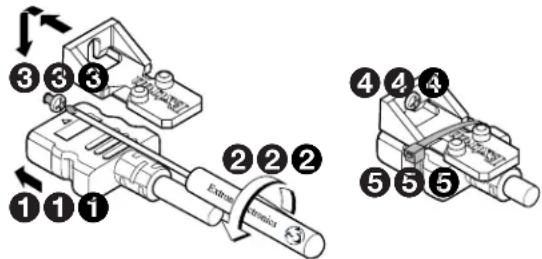
Figure 3. Installing the LockIt Lacing Bracket
- Loosen the HDMI connection mounting screw from the panel enough to allow the LockIt lacing bracket to be placed over it (2). The screw does not have to be removed.
- Place the LockIt lacing bracket on the screw and against the HDMI connector, then tighten the screw to secure the bracket (③).
ATTENTION:
- Do not overtighten the HDMI connector mounting screw. The shield to which it fastens is very thin and can easily be stripped.
-
Ne serrez pas trop la vis de montage du connecteur HDMI. Le blindage auquel elle est attachée est très fin et peut facilement être dénudé.
-
Loosely place the included tie wrap around the HDMI connector and the LockIt lacing bracket as shown (4).
- While holding the connector securely against the lacing bracket, use pliers or similar tools to tighten the tie wrap, then remove any excess length (⑤).
Analog audio connectors
See figure 4 to wire a connector for the appropriate input type. Connectors are included with the encoder, but you must supply the audio cable. Use the supplied tie-wrap to strap the cable to the extended tail of the connector.

Figure 4. Captive Screw Connector Wiring for Audio Inputs
NOTES:
- The length of exposed wires is important. The ideal length is 3/16 inch (5 mm).
- If the stripped section of wire is longer than 3/16 inch, the exposed wires may touch, causing a short circuit.
- If the stripped section of wire is shorter than 3/16 inch, wires can be easily pulled out even if tightly fastened by the captive screws.
- Do not tin the wires before installing them in the connector. Tinned wires are not as secure in the connector and could be pulled out.
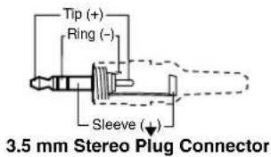
A balanced stereo audio connector consists of a tip, ring, and sleeve. An unbalanced mono audio connector consists of a tip and sleeve. When you are making connections for the units from existing audio cables, see the drawing at right to identify the tip, ring, and sleeve parts of the connector. The ring, tip, and sleeve wires are also shown on the captive screw audio connector diagram (see figure 4).
Control connector wiring
Figure 5 shows how to wire the Control RS-232/IR connector.
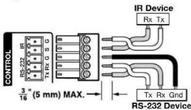
Figure 5. Control Connector Wiring
NOTES:
- The IR S and G line pair and the RS-232 Tx and Rx line pair must each cross once between this connector and the source or destination.
- The length and preparation of exposed wires is important (see the audio connector NOTES above for details).
TP cable termination
The encoder NAV 1G/PoE+ port supports 1000Mbps (1000base T — Gigabit Ethernet), half-duplex and full-duplex Ethernet connections. It is vital that your Ethernet cable be the correct cable type and that it be properly terminated with the correct pinout. Ethernet links use Category (CAT) 5e or CAT 6, unshielded twisted pair (UTP) or shielded twisted pair (STP) cables, terminated with RJ-45 connectors. Ethernet cables are limited to a length of 328 feet (100 meters).
NOTES:
- A CAT 5e cabling infrastructure is the minimum acceptable to support a NAV system. Anything less is insufficient.
- Do not stretch or bend cables. Transmission errors can occur.
The Ethernet cable must be terminated as a patch (straight-through) cable and must be properly terminated in accordance with the TIA/EIA T568-B wiring standard (see figure 6).
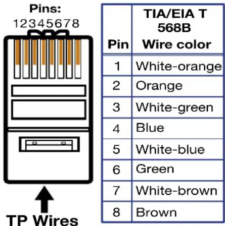
Figure 6. RJ-45 Connector and Pinout Table
Power supply wiring
Figure 7 shows how to wire the connector. Use the supplied tie-wrap to strap the power cord to the extended tail of the connector.
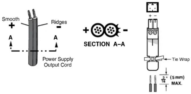
Figure 7. Power Connector Wiring
CAUTION:
ATTENTION :
• Any longer and the exposed wires may touch, causing a short circuit.
- Any shorter and the wires can be easily pulled out even if tightly fastened by the captive screws.
- Do not tin the power supply leads before installing them in the connector. Tinned wires are not as secure in the connector and could be pulled out.
To verify the polarity before connection, plug in the power supply with no load and check the output with a voltmeter.
Front Panel Features
flowchart
graph TD
    A["Extron"] --> B["CONFIG"]
    B --> C["HDMI"]
    B --> D["HDMI AUDIO"]
    B --> E["HDCP"]
    B --> F["ANALOG AUDIO"]
    C --> G["INPUTS"]
    D --> H["INPUTS"]
    E --> I["INPUTS"]
    F --> J["INPUTS"]
    G --> K["NAV LAN ID"]
    H --> L["NAV LAN ID"]
    I --> M["NAV LAN ID"]
    K --> N["STREAM LNK"]
    L --> O["STREAM LNK"]
    M --> P["STREAM LNK"]
    N --> Q["USB"]
    O --> R["USB"]
    P --> S["USB"]
    Q --> T["HOST"]
    R --> U["HOST"]
    S --> V["ACTIVE"]
    T --> W["ACTIVE"]
    U --> X["HOST"]
    V --> Y["HOST"]
    W --> Z["HOST"]
    X --> AA["HOST"]
    Y --> AB["HOST"]
    Z --> AC["LAN"]
    AA --> AD["LNK"]
    AB --> AE["ACT"]
    AC --> AF["NAV E 501"]
    AD --> AG["NAV E 101"]
    AE --> AH["NAV E 501"]
    AF --> AI["NAV E 101"]
Figure 8. Encoder Front Panel Features
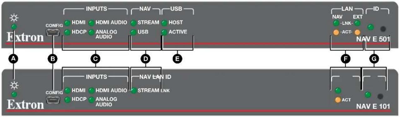
Power LED
USB LEDs (NAV E 501 only)
B CONFIGURATION port
F LAN LEDs
© INPUTS LEDs
G ID button and LED
D NAV LEDs
Power LED — Indicates power and startup status, as follows:
- Blinking — The unit is receiving power, either locally or via PoE and is booting up.
- Lit — The unit is receiving power, either locally or remotely (via PoE) and is operational.
B CONFIGURATION port — This USB mini-B port (USB 2.0) can be used to configure the encoder and to update firmware.
© INPUTS LEDs (see figure 8 on page 11) — Indicate status of the signal inputs, as follows:
• HDMI LED — The encoder is receiving an active HDMI input signal.
• HDCP LED — The HDMI signal is HDCP encrypted.
• HDMI Audio LED — The embedded HDMI audio input is selected.
• Analog Audio LED — The analog audio input is selected.
NAV LEDs — Indicate the output status of the AV and USB (NAV E 501 only) streams, as follows:
Stream LED
- Lit steadily – The encoder is actively streaming a NAV output consisting of video, audio, or both to one or more NAV decoders.
- Blinking – The encoder is actively streaming a NAV output, but network errors are present.
- Unlit - The encoder is not actively streaming a NAV output.
- USB (NAV E 501 only)
- Lit steadily – The encoder is actively sending and receiving a NAV USB stream.
- Blinking – The encoder is unable to establish a NAV USB stream.
- Unlit — The encoder is not actively sending and receiving a NAV USB stream.
USB LEDs (NAV E 501 only)— Indicate the mode and status of the rear panel USB port, as follows:
Host
- Lit steadily – The encoder is in USB host mode, the default condition.
- Unlit – The encoder is in USB device mode.
NOTES:
- You can tie a USB host only to a USB device for proper system operation.
- If you connect a host, such as a PC, to an endpoint that is in USB device mode, the endpoint cannot recognize the device.
• Active
- Lit steadily – A host or USB device is connected to the rear panel USB port.
- Unlit – No host or USB device is connected to the rear panel USB port.
- Blinking – A USB device or hub is connected to the encoder and is drawing more power than the USB port can supply.
F LAN LEDs — Indicate the status of the network connections, as follows:
- NAV LEDs (NAV E 501) or LAN LED (NAV E 101) — Indicates the NAV network connection status.
- Link LED — Indicates the status of the link.
- Lit steadily— Indicates that a network link is established at 1 Gbps.
- Blinking – Indicates that network link is established less than 1 Gbps.
- Act LED — Indicates the network traffic rate. The blink rate corresponds to activity.
- Ext LEDs (NAV E 501 only) — Indicates the Ethernet Extension status.
- Link LED — Indicates the status of the link.
- Lit steadily— Indicates that a network link is established.
- Blinking – Indicates that network link is established less than 1 Gbps.
- Act LED — Indicates the network traffic rate. The blink rate corresponds to activity.
NAV E 501 and NAV E 101 Encoders • Installation and Basic Operation 12
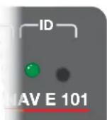
ID button and LED (see figure 8 on page 11) — The recessed ID button, when pressed, identifies the encoder to other network units and to the embedded HTML pages (see Pairing Devices Manually on page 13). The LED blinks when the encoder is in pairing mode and lights when it is paired or device identification is selected from the encoder or NAVigator HTML page.
NOTE: The ID button triggers the Status on-screen display (OSD), which shows on the LOOP THRU port (see B on page 5).
Startup and Basic Operation
Power
The encoder can be powered in one of three ways:
- Locally, from the included external power supply and via the power connector (see ⚪ on page 6).
- Remotely, receiving PoE via the NAV 1G/PoE+ port (see G); either from the network switch or from an optional PI 140 Power Injector.
- Locally (J) and remotely (G), with priority on the NAV 1G/PoE+ port. If PoE voltage drops below a threshold, the encoder immediately transitions to the power connector with no effect on system operation.
When power is applied, the encoder runs a series of self-tests that blink the front panel Power LED and all other indicators. The encoder then boots the NAV operating system. It can take approximately 45 seconds for self-test and system startup to complete. When the process is complete, the Power LED lights steadily.
NOTE: The encoder is NOT operational until the boot process is complete (the Power LED is lit steadily).
Pairing Devices Manually
Manually pair devices as follows:
- Use a Tweeker or other small screwdriver to press and hold the encoder front panel ID button for approximately 3 seconds, until the ID LED blinks. The encoder enters pairing mode.
- One at a time, use a Tweeker or other small screwdriver to press and hold the decoder front panel ID button for approximately 3 seconds, until the ID LED blinks. Release the ID button. The decoder is now paired to the encoder.
- Repeat step 2 for each decoder.
- Use a Tweeker or other small screwdriver to press and release the encoder front panel ID button. The encoder exits pairing mode.
- Repeat steps 1 through 4 to pair decoders to other encoders.
NOTE: Units can be paired manually via the ID button, but they cannot be unpaired manually. To unpair units, use the embedded HTML pages of either the decoder (see the applicable decoder user guide) or of the NAVigator (see the NAVigator User Guide). The applicable user guides are available at www.extron.com.
Operation
After the encoder, all decoders, and their connected devices are fully booted up and operational (the Power LED on each unit is lit steadily) and the devices are paired, the system is fully operational. If any problems are encountered, ensure all cables are routed and connected properly.
System operation with a NAVigator
Your NAV system must include an Extron NAVigator, a system manager that configures and controls the AV streaming system. The NAVigator allows you to make changes to multiple endpoints in the system from a central location, simplifying operations such as making ties or bulk configuration.
The base version of the NAVigator can support up to 16 endpoints by default, but if a LinkLicense is installed, support can be expanded to up to 240 endpoints, depending on the LinkLicense.
See the NAVigator User Guide, available at www.extron.com for details.
Configuration and other operations
Configuration and more complex operation of the system is accomplished via embedded web pages (see HTML Operation, beginning on page 16) or Extron Toolbelt. Simple Instruction Set (SIS) commands (see SIS Operations, starting on page 69) cannot be issued directly to the encoder, but are issued via an Extron control system on the AV network using a process known as “encapsulation” (see the NAVigator User Guide, available at www.extron.com for details).
Reset operations
The rear panel RESET button initiates three levels of resets (numbered 1, 4, and 5 for comparison with an Extron IPL product). The RESET button is recessed, so use a pointed stylus, ballpoint pen, or small screwdriver to access it.
See the table on page 15 for a summary of the modes.
ATTENTION:
- The reset modes listed in the table are separate functions, not a continuation from mode 1 to mode 5.
- The modes listed close all open IP and other connections and close all sockets.
| Reset Mode Comparison and Summary | |||
| Mode | Activation Result Purpose and | Notes | |
| 1Hardware reset | Hold down the recessed RESET button while applying power to the unit.NOTE: After a mode 1 reset is performed, update the unit firmware to the latest version. Do not operate the unit firmware version that results from the mode 1 reset. If you want to use the factory default firmware, you must upload that version again (seeFIRMWARE tabon page 38 for details on uploading firmware). | The unit reverts to the factory default firmware. All user files and settings, such as IP settings, are maintained.NOTE: If you do not want to update firmware, or you performed a mode 1 reset by mistake, cycle power to the unit to return to the firmware version that was running before the mode 1 reset (seeAbout Pageon page 64 to find the firmware version). | Use to return the unit to the factory default firmware version if incompatibility issues arise with user-loaded firmware. |
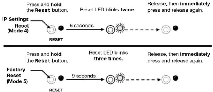
| 4Reset IP settings | Hold the RESET button for approximately 6 seconds, until the Reset LED blinks twice (once at 3 seconds and again at 6 seconds). Then momentarily press RESET within 1 second. | Resets all the IP settings without affecting the device configuration:Enables ARP capability.Sets the IP address, subnet address, gateway address, and port mapping to the factory default.Sets the Multicast IP, stream number and device name to the factory default.Turns DHCP on.The Reset LED blinks three times in succession during the reset. | Enables you to set IP address information using ARP and the MAC address. |
| 5Factory reset | Hold the RESET button for approximately 9 seconds, until the Reset LED blinks three times (once at 3 seconds, again at 6 seconds, and then again at 9 seconds). Then momentarily press RESET within 1 second.NOTE: Reverts the factory-configured username to admin and password to extron. | Performs a complete reset to factory defaults (with the exception of the firmware):Does everything mode 4 does.Resets all settings with the exception of factory firmware.Resets all IP options.Removes all files from the unit.Removes the initial serial number passwords and sets them to extron.The Reset LED blinks four times in succession during the reset. | For starting over with configuration and uploading or to replace events. Same as theEscZQQQSIS command on page 72. |
Performing mode 4 and 5 resets
Perform resets of the unit as follows (see figure 9):
- Use a small screwdriver to press and hold the rear panel RESET button until the rear panel Reset LED blinks either:
• Twice, for an IP settings reset
• Three times for an absolute (factory) reset
flowchart
graph TD
    A["IP Settings Reset (Mode 4)"] --> B["RESET"]
    B --> C["6 seconds"]
    C --> D["Reset LED blinks twice."]
    D --> E["Release, then immediately press and release again."]
    F["Factory Reset (Mode 5)"] --> G["RESET"]
    G --> H["9 seconds"]
    H --> I["Reset LED blinks three times."]
    I --> J["Release, then immediately press and release again."]
Figure 9. Resets
- Release the RESET button and then immediately press and release the RESET button again. Nothing happens if you do not momentarily RESET within 1 second.
HTML Operation
This section introduces using the built-in HTML pages to configure and operate the NAV E 501 and NAV E 101 encoders, including:
- Opening the Embedded HTML Pages
• Using the HTML Pages
The encoder can be controlled and operated through either the front panel Configuration (USB) port (see figure 8, B on page 11) or the rear panel NAV 1G/PoE+ port (see figure 2, G on page 5). The Configuration port uses IP over USB technology. The factory-embedded HTML pages are always available and cannot be erased or overwritten.
Opening the Embedded HTML Pages
Access the encoder using HTML pages as follows:
- Start the web browser.
NOTES:
- Extron recommends the following browsers to fully support the NAV system:
- Google Chrome™ — All screen images in this guide use Chrome
- Mozilla Firefox™
- Microsoft Edge™
-
The network must be properly configured for multicasting (IGMP). Failure to do so may result in degraded performance.
-
Click in the Address field of the browser and enter the IP address.
NOTES:
- For the NAV/PoE+ port, if unit does not receive an IP address from the DHCP server, it self-assigns a Link Local IP address in the range 169.254.X.X.
- Default settings:
| Port DHCP IP | address | Subnet mask | |
| Config (USB)* 203.0.113.22 | |||
| NAV 1G/PoE+ (RJ-45) On | |||
* For the Config port, the address for IP over USB CANNOT be changed.
- If you use IP over USB, Extron recommends waiting a minute after plugging in the cable for your PC to identify the USB connection as a valid Ethernet port.
- Press the keyboard
key.
NOTES:
- If you do not have the trusted SSL Certificate, the browser displays a privacy notification (see figure 10). Continue to the login dialog box as follows:
- Click the browser button that advances past the privacy notification (such as Advanced [1] in Chrome). Explanatory text and a link appear.

Your connection is not private
Attackers might be trying to steal your information from 203.0.113.22 (for example, passwords, messages, or credit cards). Learn more NET::ERR_CERT_AUTHORITY_INVALID
☐ Help improve Safe Browsing by sending some system information and page content to Google. Privacy policy

Back to safety
This server could not prove that it is 203.0.113.22; its security certificate is not trusted by your computer's operating system. This may be caused by a misconfiguration or an attacker intercepting your connection.

Figure 10. Privacy Notification
- Click Proceed to
(unsafe) (②) (or similar message).
- Your IT department can provide an uploadable SSL Certificate (see Toolbelt on page 65). Once the certificate is loaded, the notification does not occur.
The browser opens to the Login dialog box (see figure 11).
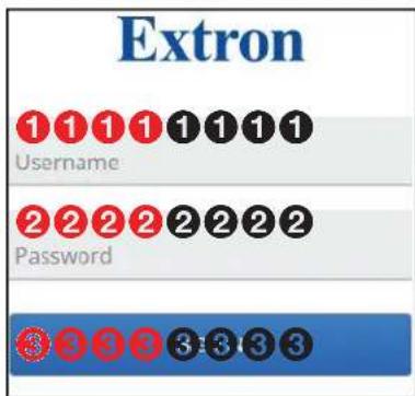
Figure 11. Login Dialog Box
- Enter the Username (see figure 11, ①) and Password (②) and click Sign In (③). The browser opens the embedded encoder web pages (see figure 12 on page 18).
NOTES:
- The factory configured passwords for all accounts on this device have been set to the device serial number. In the event of a complete system reset, the passwords revert to the default.
- The default username is admin and the default password is extron.
- Passwords are case sensitive.
NOTES: The HTML page may open with any of the panels (items ② through ⑦ below) selected.
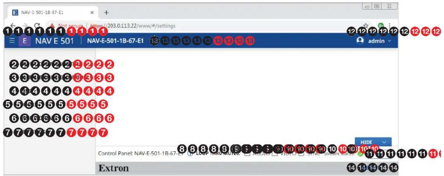
Figure 12. Home Page
See figure 12 and the detailed descriptions in Using the HTML Pages on page 19.
① Menu icon
⑧ Control Panel Information indicator
② INPUT CONFIGURATION link
⑨ LOOP THRU MUTES panel
③ OUTPUT CONFIGURATION link
10 Stream Status indicator
④ TIES link
⑪ ID button
⑤ TOOLS link
12 admin link
⑥ MONITORING link
13 Name banner
7 SETTINGS link
14 About link
Using the HTML Pages
See figure 12 on page 18 and the following sections for detailed descriptions of the following pages or functions:
① Menu icon — Toggles to hide or show the links pane (items ② through ⑦).
② INPUT CONFIGURATION link — Opens a page that provides input configuration information and the ability to change some input values (see Input Configuration Page on page 20).
③ OUTPUT CONFIGURATION link — Opens a page that provides streaming output configuration information and the ability to change some output values (see Output Configuration Page on page 23).
4 TIES link — Opens a page that displays the status of the input to the encoder and the streaming output (see Ties Page on page 33).
⑤ TOOLS link — Opens two pages that provide encoder and diagnostic tools (see Tools Page on page 34).
⑥ MONITORING link — Opens a page that shows device status information (see Monitoring Page on page 42).
7 SETTINGS link — Opens a page that provides access to many system settings (see Settings Pages on page 47).
⑧ Control Panel Information indicator — Opens a dialog box that displays the format, resolution, and rate of the input and LOOP THRU output. Click anywhere outside the dialog box to close the box.
Input Format
1920×1080@60Hz
Video Signal: HDMI | HDCP:
Loop Thru Format
1920 × 1080 @ 60Hz
Video Signal: HDMI | HDCP:

⑨ LOOP THRU MUTES panel — Select (click) Audio, Video, or Sync to toggle the mute on (do not output) and off (output) for
LOOP THRU MUTES: √ AUDIO □ VIDEO □ SYNC
NOTE: The mute function is for the LOOP THRU port output only (see B on page 5). Video, audio, and sync are still streamed to the AV network.
10 Stream Status indicator — Displays the AV stream output status of the encoder, active (√), not active ( ), or error ( )
11 ID button — Click to show the Status OSD on the LOOP THRU port (see B on page 5) and light the front panel ID LED (see G on page 13).
12 admin link — Click to display the Sign Out button. Click Sign Out to log out of the encoder HTML pages.
NOTES:
- The log in to the HTML pages automatically times out after 30 minutes of user inactivity.
- Signing out is disabled when the encoder is accessed via proxy from another device (see the NOTE on page 34).

admin
Sign Out
13 Name banner — Displays the model name and hostname.
14 About link — Opens a pane that provides information about the encoder (see About Page on page 64).
Input Configuration Page
Access the Input Configuration page (see figure 13) by clicking the link on the left side of the browser (①). The browser displays the Input Configuration panel (②).
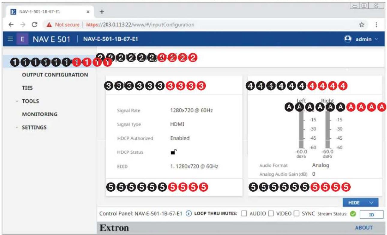
Figure 13. Input Configuration Page
The Input Configuration page consists of two read-only panes, Video (3) and Audio (4) that display the status of the input to the encoder.
The HDCP Authorized and EDID settings are accessible to change from the Video pane and the audio selected for input is accessible from the Audio pane by clicking the EDIT button (5) in the appropriate pane. The selected pane opens (see Video pane on page 21 and Audio pane on page 22).
TIP: Level meters ( A ) may help prevent overdriving the audio. The meters are present only when analog audio is being streamed (see Audio pane).
Video pane
If you change any of the settings in the Video Input Configuration dialog box (see figure 14, ① through ④), the SAVE button (⑤) becomes selectable. Click SAVE to take changes or CANCEL (⑥) to abandon them. Clicking either button closes the dialog box.
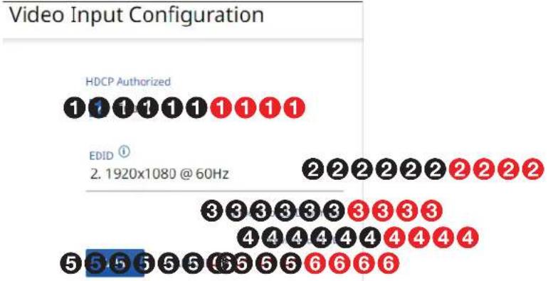
Figure 14. Video Input Configuration Dialog Box
① HDCP Authorized — Click to toggle HDCP Authorized on and off. HDCP Authorized is used to determine if the HDMI input reports as an HDCP authorized sink to a source. This helps with devices like Apple TV® that always encrypt the output even when not displaying HDCP content.
NOTE: When HDCP Authorized is selected the encoder communicates to the source device that it supports HDCP encrypted content. When deselected the encoder indicates that it does not support HDCP. If the source is unable to decrypt its output, the encoder generates a green screen.
② EDID — Click the drop-down list to select among the available EDIDs. When an EDID is selected, the encoder sends this information to the source, which adjusts its AV output to the EDID. The table below details the default encoder EDIDs. All EDIDs shown are HDMI format with 2-channel audio.
| Slot Resolution Slot Resolution | |||
| 1 | 12 | 80x720@60 Hz 5 | 3480x2160@60 Hz |
| 2 | 19 | 20x1080@60 Hz* | 6 Loop-thru monitor |
| 3 | 19 | 20x1200@60 Hz 7 | Decoder output |
| 4 | 3480x2160@30Hz | 8User EDID slot | |
| EDID12. 1920x1080 @ 60Hz |
| 1. 1280x720 @ 60Hz |
| 2. 1920x1080 @ 60Hz |
| 3. 1920x1200 @ 60Hz |
* Default
③ Import to EDID Library — Click to import a custom external EDID to the encoder EDID library, slot 8 if the EDID supplied by the encoder does not meet your needs.
NOTE: Import to EDID library (③) is disabled when the encoder is accessed via proxy from another device (see the NOTE on page 34).
Download EDID — Click to download the currently-selected EDID to the connected computer to save it for use in other encoders. This feature is typically used when EDID slot 6 (loop-thru monitor) or 7 (decoder output) is selected to save the EDID from a connected display.
Audio Pane
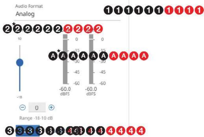
If you change any of the settings in the Audio Input Configuration dialog box (see figure 15, ① and ②), the SAVE button (③) becomes selectable. Click SAVE to take changes or CANCEL (④) to abandon them. Clicking either button closes the dialog box.
Audio Input Configuration
bar
| Range | dBFS Value | | ----------- | ---------- | | -60.0 dBFS | 0 | | -45 | -30 | | -30 | -45 | | -15 | -60 | | 0 | -60.0 | | 1 | -60.0 |* The Gain controls and level meters are present only when analog audio is being streamed.
Figure 15. Audio Input Configuration Dialog Box
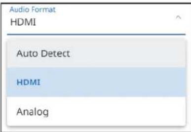
① Audio Format — Click the drop-down list to select among the following:
- Auto Detect — Stream the active audio input, with audio embedded in the input HDMI having priority. If there is no embedded HDMI audio, and if no analog audio is connected, the audio stream stays silent.
- HDMI — Stream the digital audio embedded in video. Analog audio is not streamed.
- Analog — Stream the analog audio on the captive screw input. Digital audio is not streamed.
② Gain — Adjust the audio gain or attenuation value from +10 dB to -18 dB in one of three ways:
- Click and drag the fader control.
- Click the and buttons.
- Directly type a rate into the field.
NOTE: The level meters ( A ) are present only when analog is selected, either manually (Analog) or Auto Detect).
TIP: Watching the level meters may help prevent overdriving the audio.
Output Configuration Page
Access the Output Configuration page (see figure 16) by clicking the link on the left side of the browser (①). The browser displays the Output Configuration panel (②).
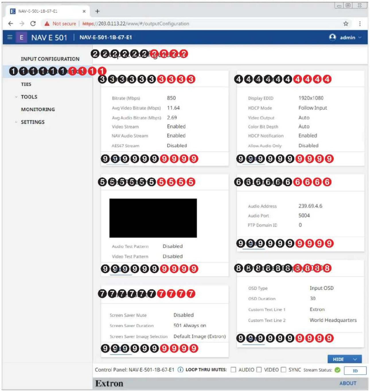
Figure 16. Output Configuration Page
The Output Configuration page consists of five panes, Stream (3), Loop Thru (4), Test Pattern (5), AES67 Audio (6), Screen Saver (7), and On Screen Display (OSD) (8) that display the status of the streamed output.
Each pane has settings that can be changed by clicking the EDIT button (see figure 16, ⑨ on page 23) in the appropriate pane. The selected dialog box opens (see "Stream pane" below, Loop Thru pane on page 25, Test Pattern pane on page 26, AES67 Audio on page 27, Screen Saver pane on page 28, and On Screen Display (OSD) pane on page 31).
Stream pane
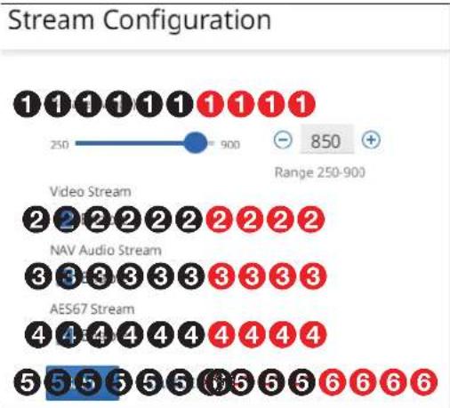
If you change any of the settings in the Stream Configuration dialog box (see figure 17, ① through ④), the SAVE button (⑤) becomes selectable. Click SAVE to take changes or CANCEL (⑥) to abandon them. Clicking either button closes the dialog box.
bar
| Stream Type | Count | | ----------------- | ----- | | Video Stream | 850 | | NAV Audio Stream | 250 | | AES67 Stream | 5 |Figure 17. Stream Configuration Dialog Box
① Bitrate — Set the Bitrate in one of three ways:
NOTE: Extron recommends leaving the bitrate at the default setting, 850 Mbps. The bitrate is the rate at which the encoder transmits data. The bitrate affects the video image quality. Decreasing the bitrate lowers the quality, increasing the bitrate improves the quality.
- Click and drag the fader control.
- Click the and buttons.
- Directly type a rate into the field.
② Video stream — Click to toggle Video Stream on (stream video) and off (do not stream).
③ NAV Audio Stream — Click to toggle NAV Audio Stream on (stream NAV audio) and off (do not stream).
NOTE: NAV Audio can only be routed to other Extron NAV products. Select NAV Audio only when your system is interfacing solely with other NAV products and the audio needs minimal processing.
④ AES67 Audio Stream — Click to toggle AES67 Audio Stream on (stream AES67 audio) and off (do not stream).
NOTE: The AES67 standard allows for interoperability among AES67 capable devices. Enabling AES67 audio allows the device to transmit a audio stream to a third-party AES67 capable receiver.
Loop Thru pane
If you change any of the settings in the Loop Thru Configuration dialog box (see figure 18, ① through ⑤), the SAVE button (⑥) becomes selectable. Click SAVE to take changes or CANCEL (⑦) to abandon them. Clicking either button closes the dialog box.
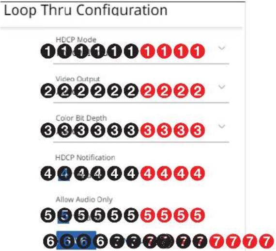
Figure 18. Loop Thru Pane
① HDCP Mode — Click the drop-down list to select between the following two output modes for the LOOP THRU port (see B on page 5).
- Follow Input — Mimics the HDCP encryption state of the connected source.
- Alway Encrypt — Maintains the HDCP encrypted state with the output sink device to improve system switching performance.
| HDCP ModeAlways Encrypt |
| Follow Input |
| Always Encrypt |
② Video Output — Click the drop-down list to select among the various output formats and colorspace for the LOOP THRU port (B). The table below shows the available formats.
| Format Format | |
| Auto (based on the EDID of the sink [default]) | HDMI YUV 444 Full |
| DVI RGB 444 HDMI YUV | 444 Limited |
| HDMI RGB 444 Full HDMI YUV | 422 Full |
| HDMI RGB 444 Limited HDMI | YUV 422 Limited |
| Video OutputDVI RGB 444 |
| Auto |
| DVI RGB 444 |
| HDMI RGB 444 FULL |
| HDMI RGB 444 LIMITED |
| HDMI YUV 444 FULL |
③ Color Bit Depth — Click the drop-down list to select between the following two output formats for the LOOP THRU port (B).
- Auto — Adjusts color bit depth based on the display EDID (10 bit or 8 bit) (default).
• Force 8-Bit — Always uses 8 bit output.
| Color Bit DepthAuto |
| Auto |
| Force 8-Bit |
④ HDCP Notification (see figure 18 on page 25) — Click to toggle HDCP Notification on and off. This selection lets you select what is displayed on the HDMI output when the input signal contains HDCP-protected content and the output is a non-HDCP sink.
When HDCP Notification is checked, a green screen is generated to clearly indicate an HDCP issue has been encountered. When HDCP Notification is unchecked, a black screen is generated to discretely show there is an HDCP issue.
This feature has no effect on the functionality of HDCP. Extron recommends leaving HDCP Notification enabled to easily know when a HDCP issue has occurred.
5 Allow Audio Only — Click to toggle Audio Only on and off. Audio only prevents a display with no video source from going to standby by generating a blackburst signal.
NOTE: Allow Audio Only must be disabled to use a screen saver.
Test Pattern pane
If you change the test pattern setting (see figure 19, ① or ②), the SAVE button (③) becomes selectable. Click SAVE to take change or CANCEL (④) to abandon it. Clicking either button closes the dialog box.
Test patterns aid in preliminary set-up of the AV system and are useful to test AV streams during initially configuration and when sources are not present.
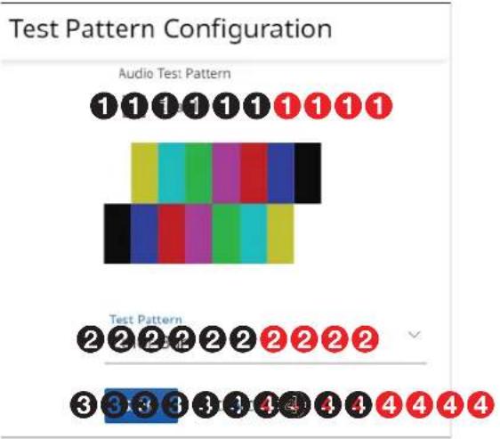
Figure 19. Test Pattern Pane
1 Audio Test Pattern — Select (click) to toggle the audio test pattern, a 400 Hz sine wave, on and off.
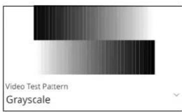
② Test Pattern — Click the drop-down list to select among test patterns to display on the Loop Thru (see B on page 5) and streamed outputs:
- Disabled (no test pattern)
• Color Bar (see figure 19) - Grayscale
AES67 pane
If you change the audio address setting (see figure 20, ②), either directly or by Reset to Default (①), or the PTP Domain ID, the SAVE button (④) becomes selectable. Click SAVE to take change or CANCEL (⑤) to abandon it. Clicking either button closes the dialog box.
AES67 Audio Configuration



Domain range 0 - 127

Figure 20. AES67 Pane
① RESET TO DEFAULT — Click this link to return the Audio Address (②) to the factory default value, 239.69.xxx.xxx where the last two octets (xxx.xxx) are based on the encoder MAC address.
② Audio Address — Click in the Audio Address field and directly enter a new address as necessary.
3 PTP (Precision Time Protocol) Domain ID — Click in the PTP Domain ID field and edit it as desired or click + or ≡ to increment or decrement the PTP Domain ID. If you change the value, the unit re-synchronizes its sits internal audio time clock to the domain of the newly entered value.
NOTE: PTP Domain is an integer value used with AES67 to logically group PTP clocks on a network. This synchronizes their clocks to eliminate latency between the audio signals. Endpoints can only synchronize to other devices in the same domain and devices outside the domain are ignored.
- If you enter a value above the valid range, such as 128, the software automatically drops the value to 127.
- If you enter a valid, but incorrect, domain, the decoder syncs to the new domain clocks and there is a potential for interrupted audio.
Screen Saver pane
This pane shows the options for the screen saver on the LOOP THRU port (see ⑧ on page 5) and streamed outputs. If you change any setting, either directly or by clicking RESET (see figure 21, ⑥), the SAVE button (④) becomes selectable. Click SAVE to take change or CANCEL (⑤) to abandon the changes. Clicking either button closes the dialog box.
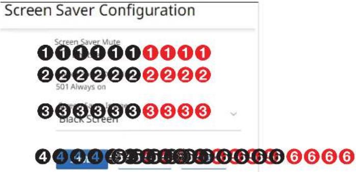
Figure 21. Screen Saver Configuration Pane
① Screen Saver Mute — Click to toggle the Screen Saver Mute on (muted) and off (unmuted) for the Loop Thru (see Ⓔ on page 5) and streamed outputs. This control sets whether the screen immediately enters low power mode (Screen Saver Mute is off) upon loss of sync or displays the user-entered screen saver image (see Screen Saver Image, ⓣ on page 29) for a period of time set by the Screen Saver Duration setting, Ⓞ.
NOTE: Allow Audio Only (see Allow Audio only, 5, on page 26) must be disabled to use a screen saver.
② Screen Saver Duration (available when Screen Saver Mute is Enabled

(1), — Click in the Duration field and edit it as desired or click for to increment or decrement the delay (in seconds) of how long the screen saver stays active and streaming, before muting sync to a display. The valid range is from 1 to 500 (seconds) or 501 Always on.
When Screen Saver Mute is unchecked (1), the duration automatically becomes 501 Always on.
After the duration expires, the encoder drops the active sync, allowing the monitor to turn off or enter low power mode.
③ Screen Saver Image (see figure 21 on page 28) — Click the drop-down list to select among the images to display as the screen saver. Retain Last Frame displays the last frame of input data before the OSD was activated. Black Screen shows a black screen. Blue Screen shows a blue screen. Default Image (Extron) displays the Extron logo. Custom Image displays an image of your choosing.
NOTES:
- To be available for selection, the custom image must be manually uploaded into the endpoint (see "Upload a custom image" below).
- If you have not already uploaded an image, the pane displays the SELECT FILE button.
- If you select the blue screen as the screen saver, the blue screen itself streams to the decoder, but any enabled OSD does not. The OSD does output on the encoder LOOP THRU port (see B on page 5).
| Screen Saver Image Default Image (Extron) |
| Black Screen |
| Blue Screen |
| Retain Last Frame |
| Default Image (Extron) |
| Custom Image |
Custom Image
SELECT FILE
Upload a custom image
You can upload a custom image to use for the screen saver background as follows:
NOTES:
- A valid custom image must be in the .png file format with a maximum size of 4K (4096 x 2160).
-
The custom image may be cropped but cannot be scaled. For example: if you upload a 1080p image and the output is 4K, you will see black borders.
-
On the editable Screen Saver Configuration pane (see figure 21 on page 28), click the Screen Saver Image drop-down list and select Custom Image (see figure 22, ①). If you have not already uploaded an image, the pane displays the SELECT FILE button (②).
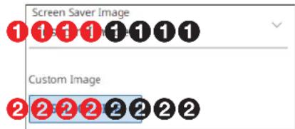
Figure 22. Upload a Custom Image, Steps 1 and 2
- Click SELECT FILE (figure 22, ② on page 29).
An Open dialog box opens (see figure 23).
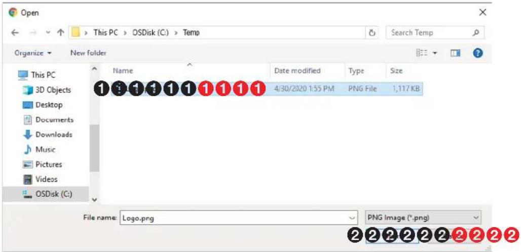
Figure 23. Open Dialog Box
-
Navigate to the folder where the image file is saved (see figure 23, ①). Select the file.
-
Click Open (2).
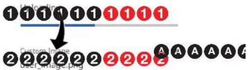
The Screensaver pane reports that it is uploading the image (①, at right) and then reports that it is the custom image (renamed user_image.png) (②).
NOTE: Click × (A) to delete the image. This action is necessary to replace the custom image.
On Screen Display (OSD) pane
This pane shows the options for the OSD and screen saver on the Loop Thru (see ⑧ on page 5) and streamed outputs. If you change any setting, either directly or by clicking RESET (see figure 24, ⑦), the SAVE button (⑤) becomes selectable. Click SAVE to take change or CANCEL (⑥) to abandon the changes. Clicking either button closes the dialog box.
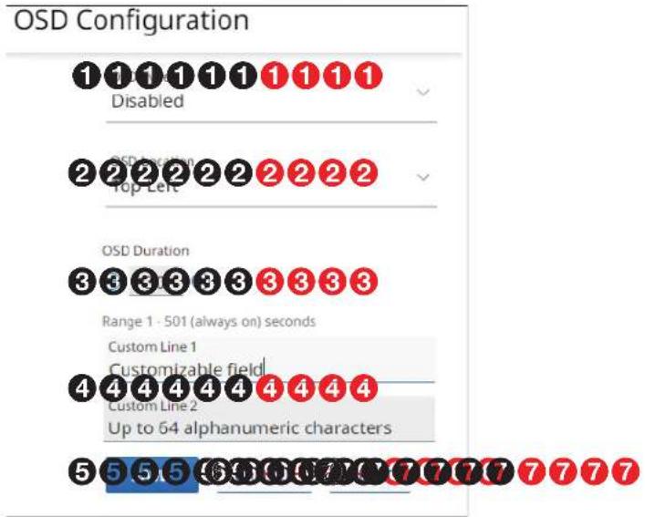
Figure 24. OSD Configuration Pane
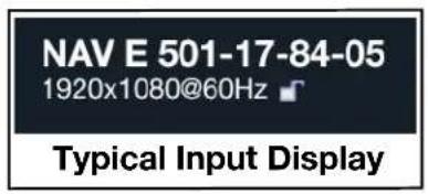
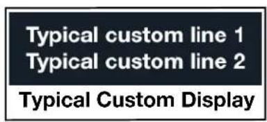
① OSD Type — Click the drop-down list to select among the OSD options for display (see figure 25 on page 32 for typical on-screen displays).
- Input OSD — Input connection details that can alert users of an input change
• Status OSD — General encoder details - Custom — User specified to indicate information pertinent to the application, such as source or security
- Disabled — No OSD
| OSD TypeInput OSD |
| Input OSD |
| Status OSD |
| Custom |
| Disabled |
NOTE: When Input OSD, Status OSD, or Custom is selected, OSD Duration appears below OSD Type (see ③) on page 32).
② OSD Location (Available only when Custom is selected [1]) — Click the drop-down list to select among the OSD location options.
| OSD LocationTop Left |
| Top Left |
| Top Right |
| Bottom Left |
| Bottom Right |
| Extron | NAV E 501 |
| Host Name | NAV-E-501-17-84-05 |
| Input Number | 1982 |
| IP Address | 192.168.1.223 |
| MAC Address | 00-05-A6-17-84-05 |
| Model | NAV E 501 |
| Serial Number | A27YDP2 |
| Firmware | FW: 1.00.0018.b100 |
| NAV Output | |
| Video Stream | Active |
| Audio Stream | Active |
| AES67 Stream | Active |
| *USB *USB Stream | Active |
| Input 1920x1080@ 60Hz | Output 1920x1080@ 60 Hz |
Typical Status Display
* NAV E 501 only
Figure 25. Typical On-Screen Displays
③ OSD Duration (available only when OSD Type is NOT Disabled [see 1 on page 28]) — Click in the Duration field and edit it as desired or click for increment or decrement the delay (in seconds) the screen saver stays active and streaming, before muting sync to a display. The valid range is from 1 to 500 (seconds) or 501 Always on.
When Screen Saver Mute is unchecked (2), the duration automatically becomes 501 Always on.
After the duration expires, the encoder drops the active sync, allowing the monitor to turn off or enter low power mode.
④ Custom Line 1 and 2 (available only when OSD Type Custom is selected [see ① on page 30]) — Click in the either Custom Line field and type in the custom information of your choice. Delete all text to clear a custom line.
NOTE: A valid custom line entry meets the following requirements:
• The length is up to 64 characters.
- All alphanumeric characters and ASCII symbols are permitted except | (pipe).
• The custom line cannot start with a space.
Ties Page
Access the Ties page (see figure 26) by clicking the link on the left side of the browser (①). The browser displays the Ties panel (②), which allows you to display AV ties and display and make AES67 ties and USB ties (NAV E 501 only).
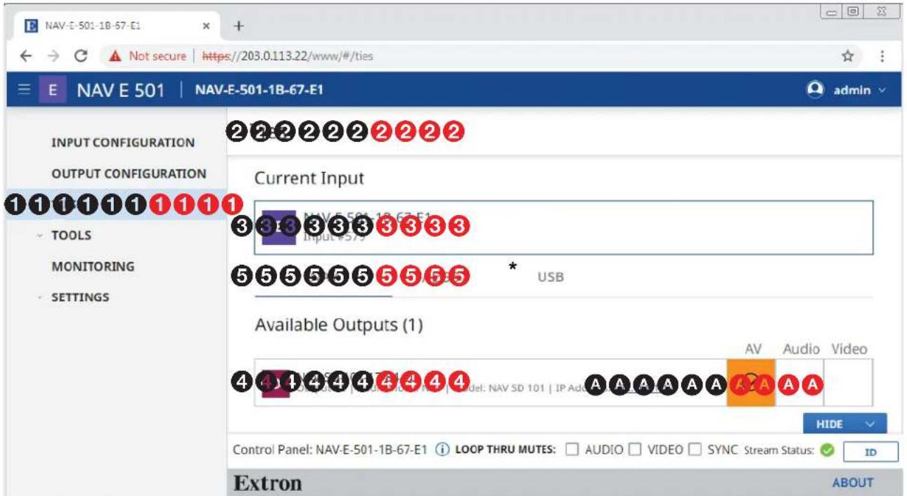
* NAV E 501 only
Figure 26. Ties Page
The Ties page consists of two panes, Current Input (3) and Available Outputs (4) that display the status of input and endpoints and tabs (5) that allow you to tailor the ties shown.
NOTES:
- Your tab display may differ from figure 26.
- The AES67 tab is present only when an Extron AES67-capable device, such as a DMP 128 ProDSP Digital Matrix Processor, is tied into the NAV system. See the user guide for the applicable device to configure that device and also the Dante documentation.
• The USB tab is present for NAV E 501 only. - AV ties are read-only on this page.
- You can make and break AES67 and USB (NAV E 501 only) ties on this page.
- You can make and break ALL ties from the embedded HTML pages of a NAVigator or decoder (see the NAVigator User Guide or the applicable decoder user guide, available at www.extron.com, and the embedded HTML tie page for those devices).
Current Input pane
The Current Input pane displays the input number and name of the encoder.
Available Outputs pane
The Available Outputs pane (see figure 26, 4 on page 33) displays the output number, audio mode, model, and IP address of all decoders available for tying to this encoder.
NOTES:
- Also on the Ties page, you can open an HTML page of a connected decoder. This is a direct page to the decoder, rather than a proxied endpoint as through a NAVigator. Click the IP Address link in the desired output (A). The HTML page opens a new tab in the browser that is connected to the selected decoder. The decoder HTML page behaves as described in the guide for the decoder (see the applicable decoder guide available at www.extron.com).
- When you select the AES67 tab or USB tab (NAV E 501 only) (see figure 27), the appearance of the Available Outputs pane changes. The name changes to Available Devices and only decoders that can receive streamed AES67 or USB ties are shown.
NAV
USB
Available Devices (1)

NAV-SD-501-1B-67-61
Model: NAV SD 501 | IP Address: 192.168.1.16




Figure 27. Available Devices for USB Tab
- To tie AES67 or USB from this encoder to a decoder, select that tab and click the desired decoder (Available Device(s)[see figure 27, A]). An AES67 audio tie is indicated in red and a USB tie is included in yellow. Click in an existing tie to untie it.
Tools Pages
The Tools pages provide tools for the encoder (Device Tools) and a tool for diagnosing communications (Diagnostic Tools). To access the Settings pages, if necessary, click the Menu link (see figure 12, ① on page 18). Click TOOLS (see ① at right) and either Device Tools (②) or Diagnostic Tools (③). The browser displays the selected Tools page (see figure 28 on page 35, which shows the Device Tools page selected).
Device Tools page
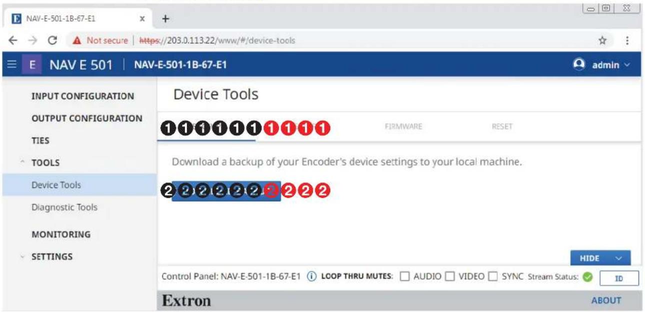
Figure 28. Device Tools Page
The Device Tools page consists of four tabs (see figure 28, ①): BACKUP (see "BACKUP tab" below) RESTORE (see RESTORE tab on page 36), FIRMWARE (see FIRMWARE tab on page 38) and RESET (see RESET tab on page 39) that provide encoder tools.
NOTE: System backup, restore, firmware update, and reset are available from the NAVigator (see the Navigator User Guide, available at www.extron.com).
BACKUP tab
Backup the encoder settings as follows:
NOTE: Backup is disabled when the encoder is accessed via proxy from the NAVigator.
- On the Device Tools page, click BACKUP (see figure 28, ①).
- Click DOWNLOAD BACKUP (②).
The encoder creates a file of current settings and, depending on your browser, may prompt you to confirm that you want to save them.

This type of file can harm your computer. Do you want to keep backup-NAV-E-10....cfg anyway?
Keep
Discard
NOTE: Unless otherwise directed, the encoder backup file goes to the Downloads folder of the connected PC.
- Click Keep to save the file to the Downloads folder or Discard as desired.
RESTORE tab
Restore the encoder settings as follows:
NOTE: Restore is disabled when the encoder is accessed via proxy from the NAVigator.
- On the Device Tools page, click RESTORE (see figure 29, ①).
- Click SELECT FILE (②).
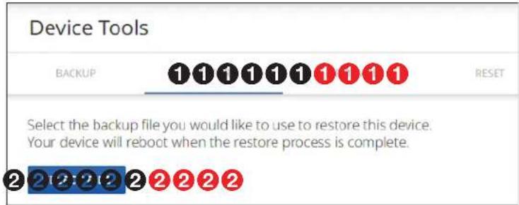
Figure 29. Tools — Restore Function
An Open dialog box opens (see figure 30).
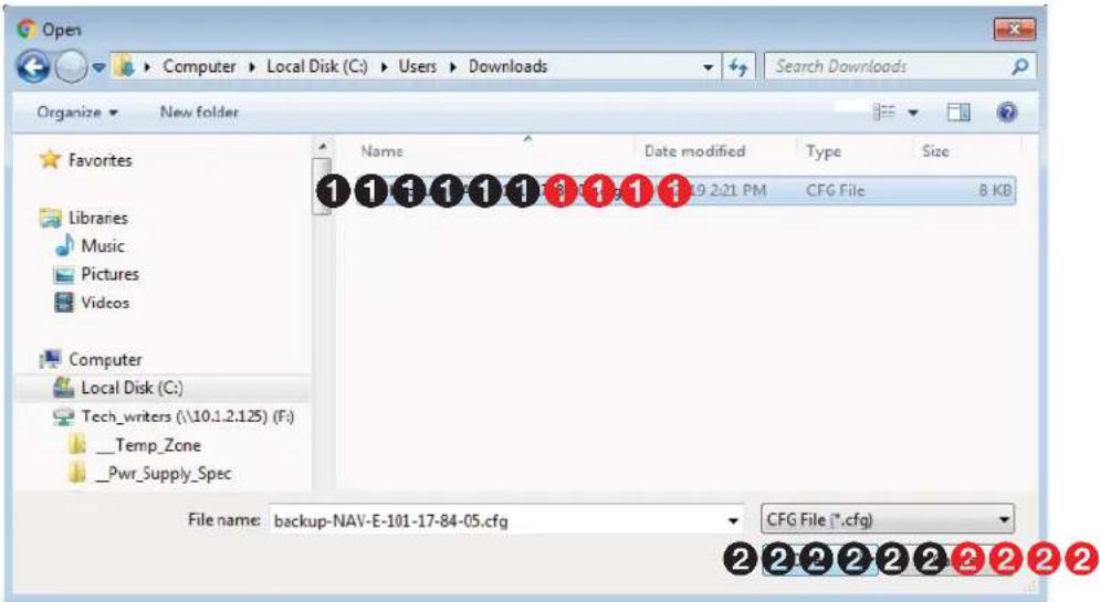
Figure 30. Open Dialog Box
- Navigate to the folder where the Restore file is saved (typically the Downloads folder) (see figure 30, 1). Select the file.
- Click Open (2). The Tools page returns to the top (see figure 31 on page 37).
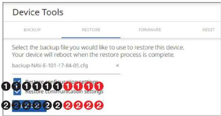
Figure 31. Tools — Restore Function, Steps 5 and 6
- Select (click) the settings to restore (Configuration, Communication, or both; see figure 31, ①).
| Communication settings Configuration settings | ||
| Settings > General > Device Details (name) | Settings > General > Device Details (location) | Output Config. > Stream |
| Settings > Networking > Network Connection | Settings > General > Date and Time | Output Config. > Loop Thru |
| Settings > General > USB (NAV E 501 only) | Output Config > AES67 Audio | |
| Settings > Advanced | Output Config > OSD | |
| Input Config. > Video | Output Config > Screen Saver | |
| Input Config. > Audio | ||
NOTE: Account password and custom image file are not backed up.
- Click RESTORE (②).
The encoder reports that it is Rebooting and displays a status bar that shows the progress of the Restore operation. When the operation completes, the encoder reboots.
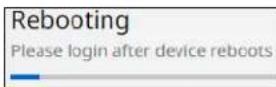
NOTE: You must reconnect to the encoder (see Opening the Embedded HTML Pages on page 16) if you have additional operations to perform.
FIRMWARE tab
Upgrade the encoder firmware as follows:
NOTES:
- Firmware upgrade is disabled when the encoder is accessed via proxy from the NAVigator.
- Upgrading the encoder firmware results in the unit rebooting.
-
Valid firmware files have the .eff file extension. Any other file extension is not a valid firmware update.
-
On the Device Tools page, click FIRMWARE (see figure 32, ①).
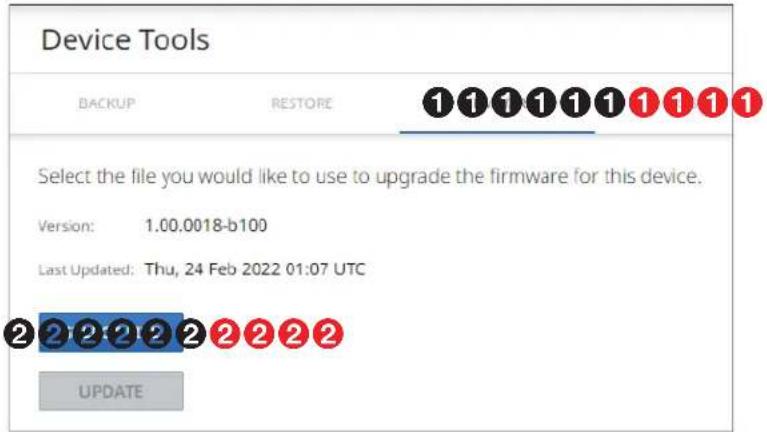
Figure 32. Tools — Firmware Function
- Click SELECT FILE (②). An Open dialog box opens (see figure 33).
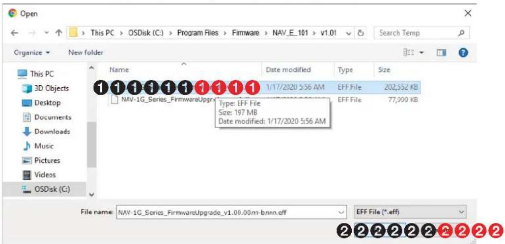
Figure 33. Open Dialog Box
- Navigate to the folder where you saved the firmware upgrade file (see figure 33, ①). Select the file.
- Click Open (2). The Open dialog box closes and the Tools pane returns to the top, with the selected firmware file identified (see figure 34, 1 on page 39).
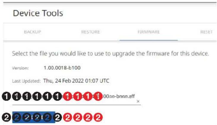
Figure 34. Device Pane with Firmware File Identified
5. Click UPDATE (2).
The encoder page displays a sequence that reports the progress as it uploads the file (see figure 35, ①), updates the firmware (②), and then reboots (③).

flowchart
graph LR
    A["Uploading 83%"] --> B["Updating File"]
    B --> C["Uploading 32%"]
    C --> D["Rebooting"]
Figure 35. Firmware Upload Progress
When the encoder reboots, the connection to it is momentarily lost and after a few seconds, the browser displays the home page Login dialog box (see figure 11 on page 17). To continue to operate the encoder, you must reconnect (see Opening the Embedded HTML Pages on page 16).
RESET tab
Reset or reboot the encoder as follows:
- On the Device Tools page, click Reset (see figure 36, ①).
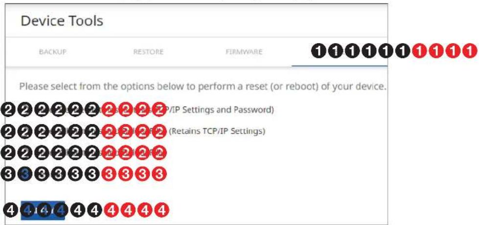
Figure 36. Tools — Reset Function
- Select (click) a reset level (see figure 36, ② on page 39) or Reboot (③).
NOTES:
- Reset Device Settings (Retains TCP/IP Settings and Password) — Resets configuration settings. All communication settings and the password are retained. See the table of communication and configuration settings on page 37.
- Reset All Settings and Delete Files (Retains TCP/IP Settings) — Resets configuration settings except the communication settings, which are maintained. Resets the password to the default, which is extron. See the table of communication and configuration settings.
- Reset All Settings and Delete Files — This reset is identical to the Mode 5 reset (see the table of rear panel reset modes on page 15), which resets all settings to factory defaults.
3. Click APPLY (4).
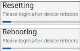
The encoder reports that it is Resetting and Rebooting and displays a status bar that shows the progress of the operation. Any of these operations concludes with the encoder rebooting.
NOTE: You must reconnect to the encoder (see Opening the Embedded HTML Pages on page 16) if you have additional operations to perform.
Diagnostic Tools page
The Diagnostic Tools page (see figure 37) provides tools that allow you to troubleshoot the connection to other units on the NAV network. Access the page as follows:
- Click the TOOLS > Diagnostic Tools link on the left side of the browser (①). The browser displays the Diagnostic Tools page.
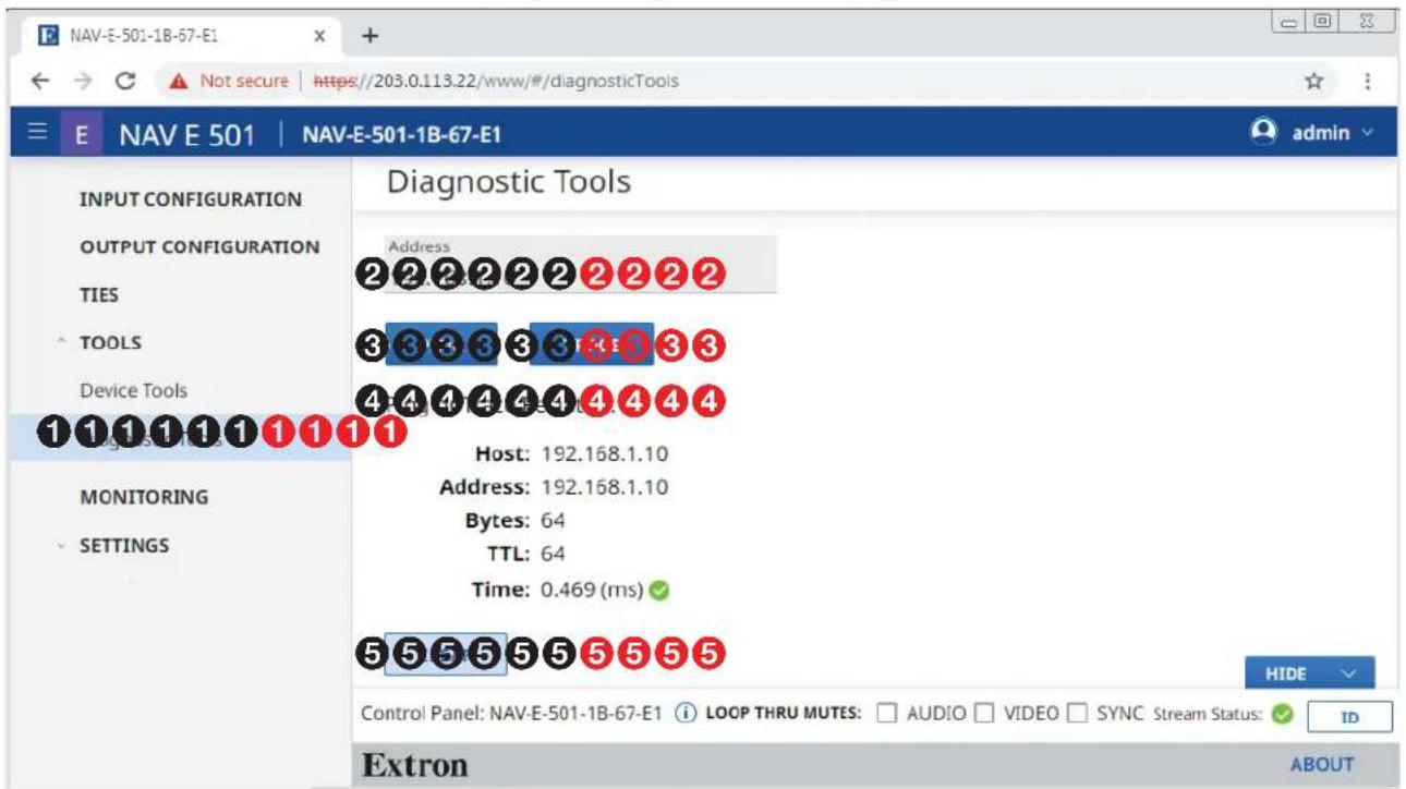
Figure 37. Diagnostic Tools Page, Ping Results Shown
- Click in the Address field and type in the IP address of another unit on the network (②).
- Click either PING or TRACE (③), depending on the diagnostic you want to run.
NOTES:
- Ping — Tests the connection to another unit on the network. Figure 37, 4 shows the typical results of a Ping diagnostic. If you see the message Ping to Host Address has Timed Out..., contact your system administrator to troubleshoot.
- Trace — Traces the network route taken by a packet from source to destination and displays the network packet path as it traverses the network. If a trace is not fully successful, the diagnostic displays where the packet was last successful before it stopped and can no longer communicate to the next hop. Figure 38 shows the typical results of a Trace diagnostic.
Ping or Trace Results....
traceroute to 192.168.1.10 (192.168.1.10), 30 hops max, 46 byte packets 1 192.168.1.10 (192.168.1.10) 0.373 ms 0.325 ms 0.289 ms
CLEAR
Figure 38. Trace Results Shown
- Click CLEAR (⑤) to reset the Address field if you want to run another diagnostic.
Monitoring Page
Access the Monitoring page (see figure 39) by clicking the link on the left side of the browser (①). The browser displays the Monitoring page (②), which shows device status information.
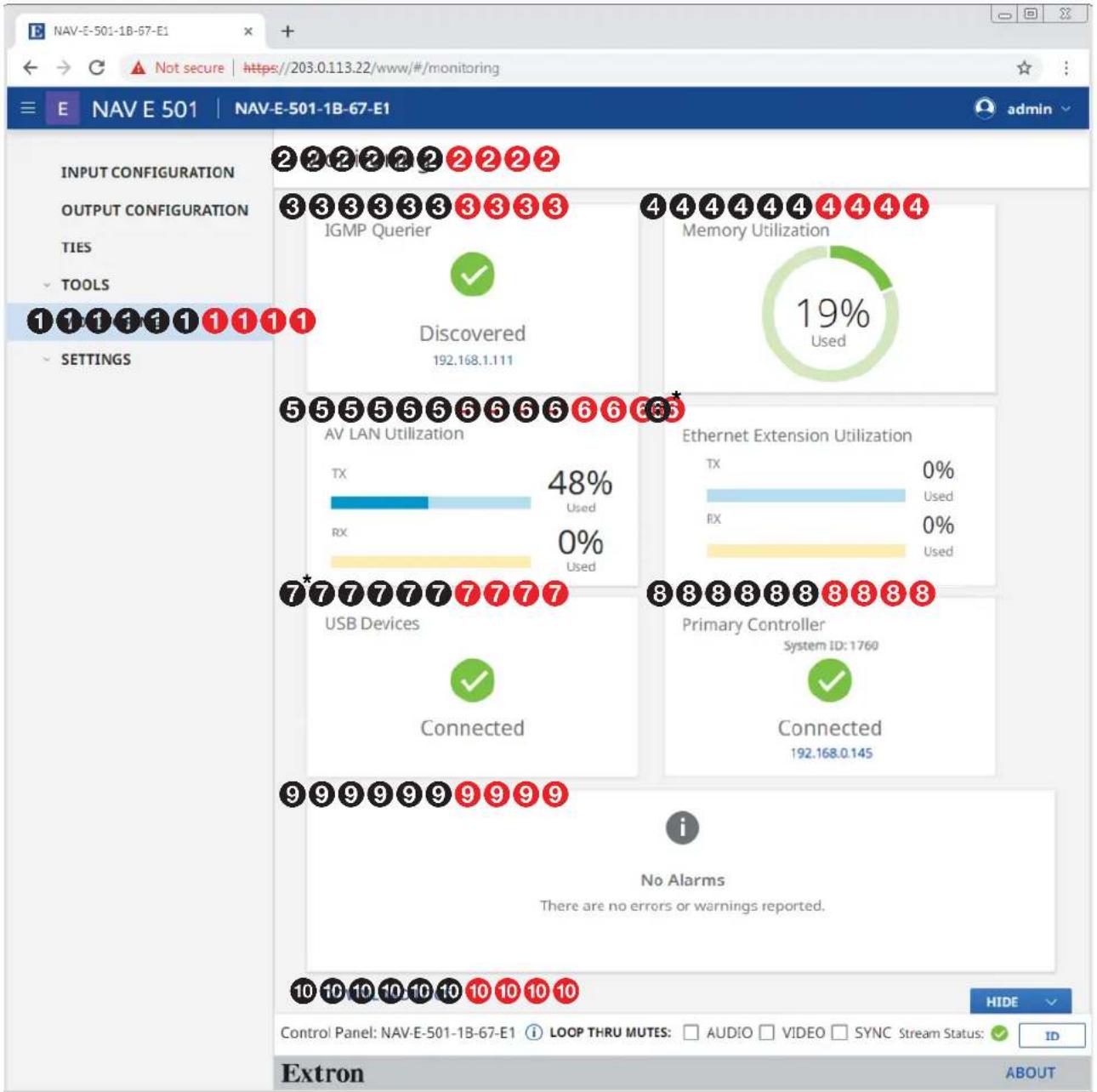
* NAV E 501 only
Figure 39. Monitoring Page
③ IGMP Querier
④ Memory Utilization
⑤ AV LAN Utilization
⑥ Ethernet Extension Utilization (NAV E 501 only)
⑦ USB Devices (NAV E 501 only)
⑧ Primary Controller
⑨ Alarms
10 Download Logs
③ IGMP Querier pane (see figure 39 on page 42) — See “IGMP Querier pane.”
④ Memory Utilization — Indicates encoder memory usage, expressed in percent.
⑤ AV LAN Utilization — Indicates the total bandwidth usage at that moment. The encoder generates an alarm if the utilization goes above 90%. The alarm clears automatically once the level drops below 90%.
NOTE: The encoder normally uses far more Tx than Rx bandwidth.
⑥ Ethernet Extension Utilization pane (NAV E 501 only) — See "Ethernet Extension Utilization pane."
7 USB Devices pane (NAV E 501 only) — See USB Devices pane on page 44.
⑧ Primary Controller pane — See Primary Controller pane on page 44.
⑨ Alarms pane — See Alarms pane on page 45.
10 Download Logs link — See Download Logs link on page 46.
IGMP Querier pane
An IGMP querier is a network service, usually running on a network switch, that can initiate IGMP queries. An IGMP querier should be configured on the NAV network. It manages the multicast traffic. If there is no IGMP querier on the network, there is no effective multicast traffic management and the multicast traffic saturates the network and stream and communication errors can occur.
The IGMP Querier pane (see figure 39, ③) shows whether or not an IGMP querying device is present on the network, and the IP address of the IGMP querier. Figure 40 shows the normal indication and if no IGMP querier is present on the network.
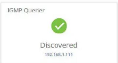
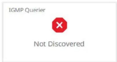
IGMP Querier Discovered IGMP Querier Not Discovered
Figure 40. IGMP Querier Pane Indications
Ethernet Extension Utilization pane (NAV E 501 only)
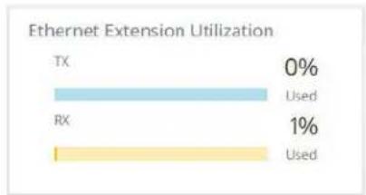
The Ethernet Extension Utilization pane (see figure 39, Ⓐ on page 42) indicates the total bandwidth usage of the rear panel Extension port (see figure 2, Ⓗ on page 5) at that moment. The encoder generates an alarm if the utilization goes above 90%. The alarm clears automatically once the level drops below 90%. Figure 41 shows the normal indication and if the Extension port is either disabled (see Networking page on page 55) or enabled with no device connected to it.
bar
Ethernet Extension Utilization | Category | Percentage (%) | | :--- | :--- | | TX | 0 | | RX | 1 | The chart displays two categories: 'Used' and '0%', with each category represented by a distinct color bar. No numerical values are provided for the bars.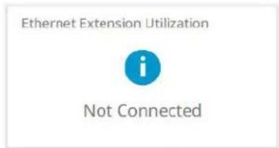
Ethernet Extension Normal Indication Ethernet Extension Disabled or Not Connected
Figure 41. Ethernet Extension Utilization Pane Indications
USB Devices pane (NAV E 501 only)
The USB Devices pane (see figure 39, 7) shows whether or not one or more USB devices are connected and NAV USB extension is enabled. Figure 42 shows the normal indication and if no USB devices are connected or the USB Host has forced the USB bus into a suspend state.
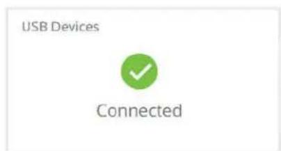
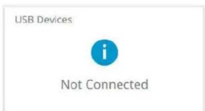
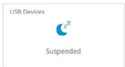
USB Devices Normal Indication USB Devices Suspended Indication USB Devices Not Connected
Figure 42. USB Devices Pane Indications
Primary Controller pane
The Primary Controller pane (see figure 39, 8) shows whether or not an Extron control processor, such as an IPCP Pro xi Control Processor, is paired with the NAV device, and the IP address of the device if present. Figure 43 shows the normal indication and if no primary controller is present on the network available or an endpoint is not connected to any controller.
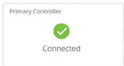
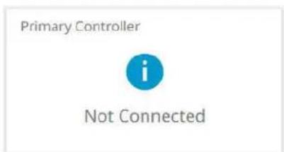
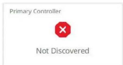
Primary Controller Normal Indication Primary Controller Not Discovered Primary Controller Not Connected
Figure 43. Primary Controller Pane Indications
Alarms pane
The Alarms pane (see figure 39, ⑨ on page 42) shows any current alarms. Figure 44 shows the pane when alarm indications are present (see Alarms on page 75). Some alarms self-clear when specific conditions are met, others remain as long as the condition that causes it remains. As an example, a temperature alarm remains until the encoder cools down.
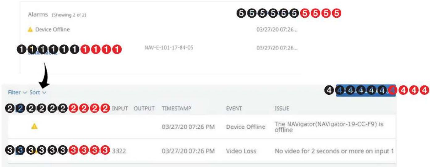
Figure 44. Clearing Alarms
NOTES:
• Critical alarms ( ) should be resolved immediately.
- Warning alarms ( ) are less serious.
Manually clear one or more alarms from the system as follows:
- Click LEARN MORE (see figure 44, ①).
- Click the A11 checkbox (②) or individual endpoint checkboxes (③) to select one or more alarms to clear.
- Click CLEAR ALARMS (④) to clear this alarm.
Configure which alarms are and are not reported in this field as follows:
- Click ALARM SETTINGS (see figure 44, ⑤ on page 45). The Edit Alarms Settings dialog box opens (see figure 45).
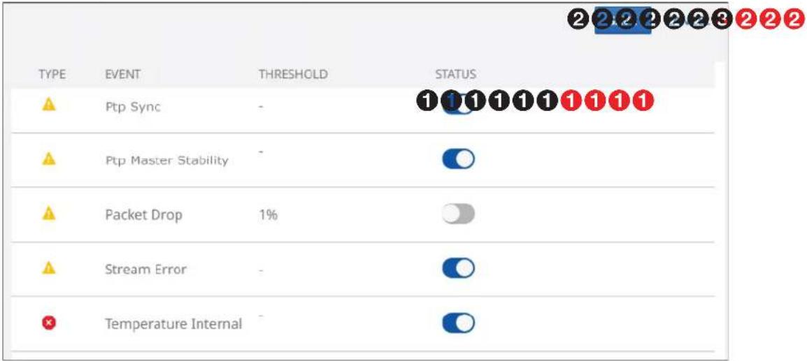
Figure 45. Edit Alarm Settings Dialog Box
- Click the STATUS switch (1) to enable () and disable () alarm reporting.
- Click SAVE (②) to make the changes or CANCEL (③) to abandon them.
Download Logs
Click the DOWNLOAD LOGS link (see 1 at right) to download a history of errors in a comma-delimited .csv file that can be opened in Microsoft Excel. The figure at right shows the results of downloading an alarms log using the Chrome browser (2).
NOTES:
- Logs are a diagnostic tool that assists in troubleshooting or debugging. NAV devices log system changes that occur and time stamp each entry to assist in tracking the sequence of events that lead up to an issue. Logs can be reviewed to better understand the cause of failure.
- There is no upper limit to the number of alarms that can be logged, but a device can only have one alarm of the same type active at a time. The encoder monitors the active alarm states of all devices in the NAV system. All alarm state changes are logged even if status reporting is disabled from the encoder.
Settings Pages
The Settings pages provide access to many system settings grouped as General, Networking, and Advanced. To access the Settings pages, if necessary, click the Menu link (see figure 12, ① on page 18). Click SETTINGS (see ① in the illustration at right) and select among General (②), Networking (③), or Advanced (④). The browser displays the Device Settings page (①) with the selected group of settings open (see figure 46, which shows the General group page (②) selected).
General page
Click the down arrow (①) to open a drop-down menu (see Device Details on page 48, Date & Time on page 50, Username/Password on page 52 or USB (NAV E 501 only) on page 53).
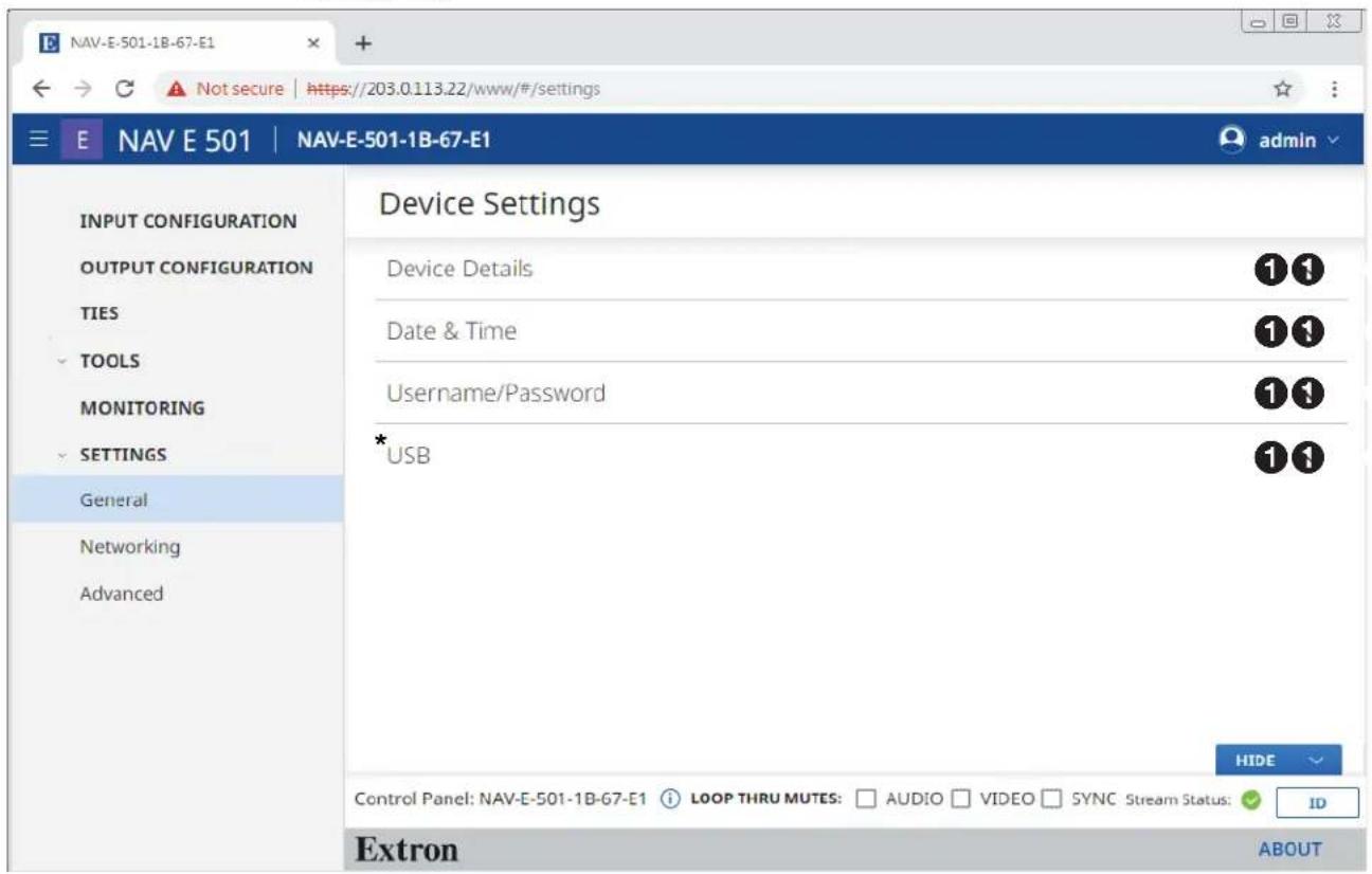
* NAV E 501 only
Figure 46. General Settings Page
Device Details page
The Device Details selection on the General Settings page (see figure 46 on page 47) opens a read-only pane that shows general information unique to the encoder (see figure 47). The Device Name, Input Number, and Location can be edited by clicking the EDIT button (①). An editable version of the selection opens (see figure 48 on page 49).
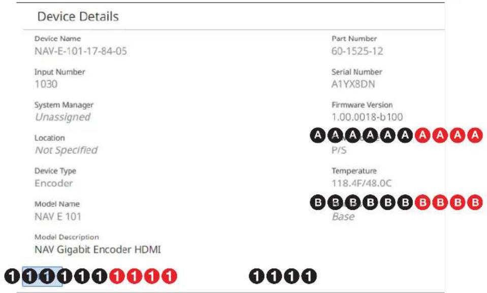
Figure 47. Device Details Selection
NOTES:
- Editing of Device Detail settings is disabled and the EDIT button is unavailable for selection when the encoder is assigned to a NAVigator.
- Special characters, which are not allowed in tags, names, and locations, are as follows: ! \~ ` @ # \$ % ^ & * () _ + = {} [ ] \ : ; “ ‘ < > , . ? and / . A hyphen (-) is not a special character.
- Tags, names, and locations each have a 63-character limit.
| Tag Rules Name Rules | Location Rules | |
| Cannot begin or end with a hyphen.Cannot begin with a space.Spaces are allowed after the first character.Multiple tags are allowed, making filtering and sorting searching easier. | Must begin with a letter.Cannot end with a hyphen.Spaces are not allowed. | Must begin with a letter.Cannot end with a hyphen.Hyphens are allowed in any other position.Cannot begin with a space.Spaces are allowed after the first character. |
- The read-only Power Source datum (A) indicates the power source of the encoder: P/S (power supply) or PoE.
- The read-only Features datum (B) indicates the configuration of the encoder: USB & Eth Extension (NAV E 501) or Base (NAV E 101)
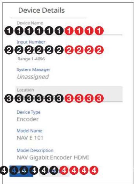
Figure 48. Editable Device Details Pane
① Device Name — Click in this field and type in a device name of your choice.
NOTE: The Device Name is also the "hostname."
② Input Number — Click the ⊖ and + buttons or type a number into the field to overwrite the factory default input number, which is automatically generated in the range from 1 to 4096.
③ Location — Click in this field and type in a location to customize your system.
④ SAVE and CANCEL buttons — Click SAVE to take Device Details changes or CANCEL to abandon them. Clicking either button closes the editable pane.
Date & Time page
The Date & Time selection on the General Settings page (see figure 46 on page 47) opens a read-only pane that shows date and time settings (see figure 49). Click SET MANUALLY (①) and SYNC WITH SERVER (②) to switch between the views applicable to each selection. The date and time can be edited by clicking the EDIT button (③). An editable pane opens (see "Set time manually" and figure 50 and Sync time with server and figure 52 on page 51).
NOTE: Editing of these settings is disabled and the EDIT button is unavailable for selection when the encoder is assigned to a NAVigator.
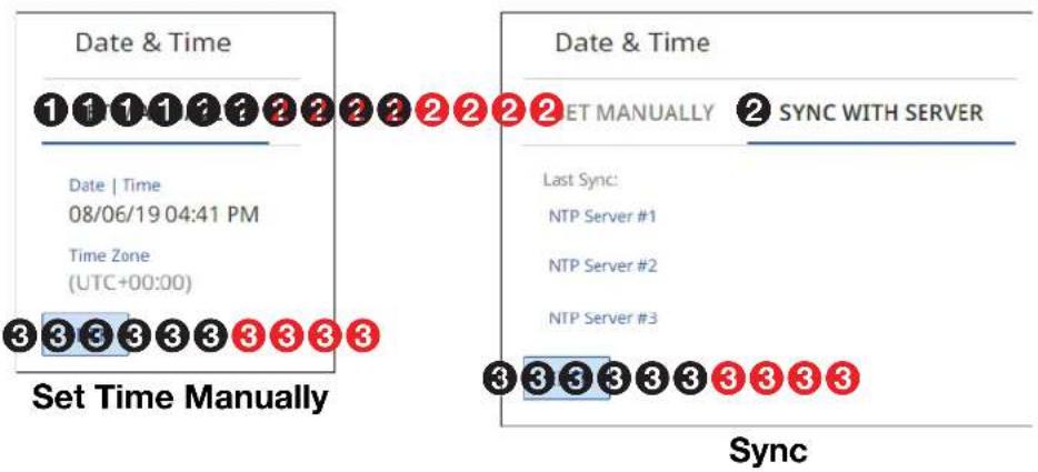
flowchart
graph TD
    A["Set Time Manually"] --> B["Date & Time"]
    B --> C["1 1 1 1 1 2 2 2 2 2 2 2 2 2 2 2 2 2 2 2 2 2 2 2 2 2 2 2 2 2 2 2 2 2 2 2 2 2 2"]
    B --> D["Date | Time\n08/06/19 04:41 PM\nTime Zone\n(UTC+00:00)"]
    B --> E["3 3 3 3 3 3 3 3 3 3 3"]
    F["Sync"] --> G["SET MANUALLY"]
    G --> H["2 SYNC WITH SERVER"]
    H --> I["Last Sync:\nNTP Server #1\nNTP Server #2\nNTP Server #3"]
    I --> J["3 3 3 3 3 3 3 3 3 3 3"]
Figure 49. Date & Time Selection
Set time manually —
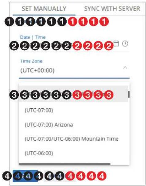
Figure 50. Set Time Manually
① Set from PC — Click this link to sync the encoder date and time to the computer with which you are connected.
② Date & Time — Click in this field and type in the date and time.
③ Time Zone — Click the drop-down list to select the offset from Greenwich Mean Time (GMT).
4 SAVE and CANCEL buttons (see figure 50 on page 50) — Click SAVE to take Date & Time changes or CANCEL to abandon them. Clicking either button closes the editable pane.
NOTE: Or you can click the Datepicker (☐) or Timepicker (☐) icons (see figure 50) and use those tools to set the date and time (see figure 51).
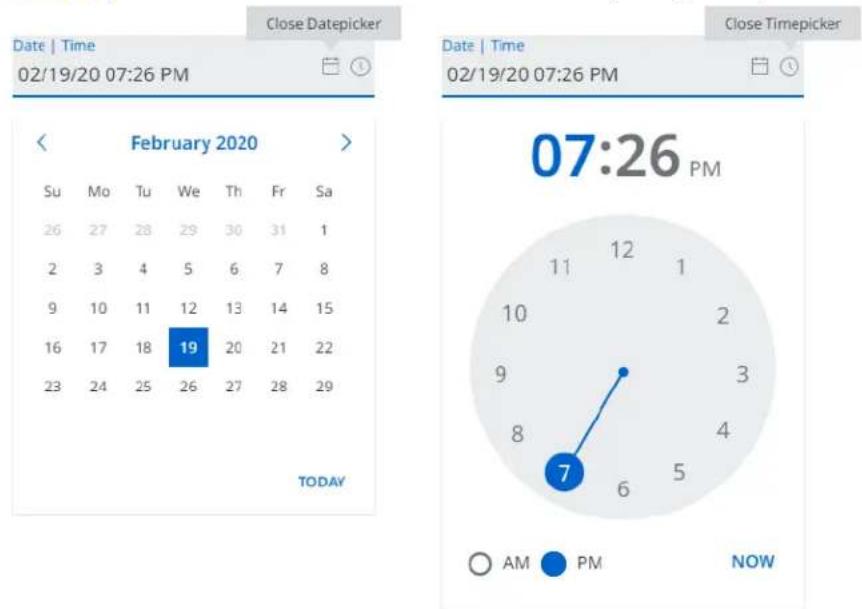
Figure 51. Using Datepicker and Timepicker Tools
Sync time with server —
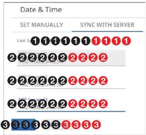
flowchart
graph TD
    A["SET MANUALLY"] --> B["SYNC WITH SERVER"]
    B --> C["Last System 1"]
    B --> D["2 2 2 2 2 2 2 2 2 2"]
    B --> E["3 3 3 3 3 3 3 3 3 3"]
    C --> F["ATP System 2"]
    D --> G["ATP System 3"]
    E --> H["ATP System 4"]
Figure 52. Sync Time with Server
① SYNC NOW — Click to force the encoder to sync its internal clock to an NTP server.
② NTP server — Click in these fields and type in the IP address or DNS name of an NTP server.
③ SAVE and CANCEL buttons — Click SAVE to take Date & Time changes or CANCEL to abandon them. Clicking either button closes the editable pane.
Username/Password page
The Username/Password selection on the General Settings page (see figure 46 on page 47) opens a read-only pane that shows the credentials of the encoder (see figure 53). The Password can be edited by clicking the EDIT button (①). An editable version of the selection opens (see figure 54).
NOTES:
- Editing of these settings is disabled and the EDIT button is unavailable for selection when the encoder is assigned to a NAVigator.
- Any devices assigned to the NAVigator inherit the password of that NAVigator.
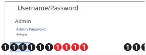
Figure 53. Username/Password Selection
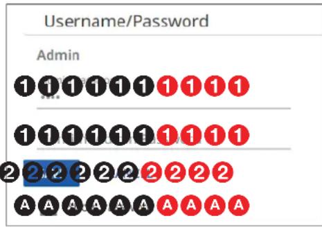
Figure 54. Editable Username/Password Selection
① Password and Confirm Password — Click in these fields and type in valid password values to enter the appropriate values for your encoder.
NOTES:
- A valid password meets the following requirements:
• The length is up to 64 characters. - All alphanumeric characters and ASCII symbols are permitted except | (pipe).
• The password cannot be blank. - The password cannot start with a space.
- The factory configured passwords for all accounts on this device have been set to the device serial number. In the event of a complete system reset, the passwords revert to the default.
- The default username is admin and the default password is extron.
TIP: Select (click) the Show Password checkbox (A) to display the password as you type it.
② SAVE and CANCEL buttons — Click SAVE (②) to take Password change or CANCEL to abandon it. Clicking either button closes the editable pane.
USB page (NAV E 501 only)
The USB selection on the General Settings page (see figure 46 on page 47) opens a read-only pane (see figure 55) that shows the status of the USB 2.0 port (see F on page 6). The port can be turned on and off and it can be configured by clicking the EDIT button (1). An editable version of the selection opens (see figure 56).
*
1111111111
* If the endpoint is set to Host mode only.
Figure 55. USB Selection

* If the endpoint is set to Host mode only.
Figure 56. Editable USB Selection
① USB Port — Click to toggle the port on and off.
NOTE: If you turn the USB port off, the endpoint does not appear on the USB Ties page.
② Mode — Click the drop-down list to select between Device and Host.
NOTES:
- Host mode allows a host device such as a PC to be connected or accepted to that endpoint.
• Device mode allows devices to be connected or accepted to that endpoint. - You can only tie a USB host to a USB device for proper system operation.
- Do not connect a host to an endpoint that is in USB device mode.
③ Device Class Filtering (see figure 56 on page 53) — Click the drop-down list to select among USB 2.0, HID + CAC, and HID Only.
NOTE: USB Device Class filtering limits the functionality of the USB port.
- USB 2.0 — No restrictions, allows all USB devices to function.
- HID + CAC — Allows only devices such as a keyboard, mouse, and a card reader (common access card) to function.
- HID Only — Allows only devices such as a keyboard and mouse to function.
HID Only
HID + CAC
USB 2.0
4 Peripheral Emulation — This feature, available only if the endpoint is set to Host mode, emulates a keyboard and mouse to the connected host computer, allowing faster USB switching.
⑤ SAVE and CANCEL buttons — Click SAVE to take USB changes or CANCEL to abandon them. Clicking either button closes the editable pane.
Networking page
On the Networking Settings page (see figure 57), click the down arrow (①) to open a drop-down menu (see Network Connection page on page 56 or Port page on page 58).
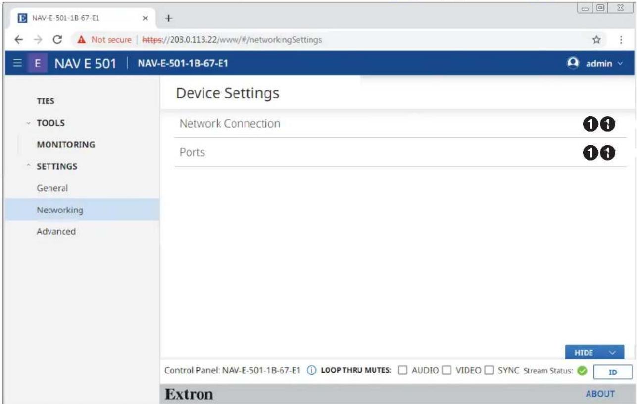
Figure 57. Networking Settings Page
Network Connection page
The Network Connection selection on the Networking Settings page (see figure 57 on page 55) opens a read-only pane that shows the connection variables of the encoder (see figure 58). DHCP, IP Address, Subnet, Gateway, DNS Server, DNS Suffix, and Ethernet Extension (NAV E 501 only) can be edited by clicking the EDIT button (①). An editable pane opens (see figure 59 on page 57).
NOTES:
- Ethernet Extension (NAV E 501 only) is Off by default.
- Editing of these settings is disabled and the EDIT button is unavailable for selection when the encoder is assigned to a NAVigator.
Network Connection
Link Speed
1 Gbps
DHCP
On
IP Address
169.254.6.11
Subnet
255.255.0.0
Gateway
0.0.0.0
DNS Server
0.0.0.0
DNS Suffix
Not Specified
Link Local
169.254.6.11
MAC Address
00-05-A6-17-84-05
* Ethernet Extension On

* NAV E 501 only
Figure 58. Network Connection Pane
NOTE: IP Address, Subnet, Gateway, DNS Server, and DNS Suffix are not editable when DHCP is on.
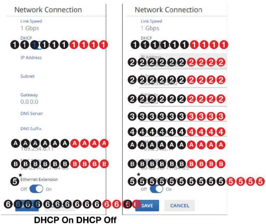
other
Network Connection | State | IP Address | Node ID | Link Speed (Gbps) | | :--- | :--- | :--- | :--- | | IP Address | 2 | 2 | 1 | | IP Address | 2 | 2 | 1 | | IP Address | 2 | 2 | 1 | | IP Address | 2 | 2 | 1 | | IP Address | 2 | 2 | 1 | | IP Address | 2 | 2 | 1 | | IP Address | 2 | 2 | 1 | | IP Address | 2 | 2 | 1 | | IP Address | 2 | -3 | 1 | | IP Address | -3 | -3 | 1 | | IP Address | -3 | -3 | 1 | | IP Address | -3 | -3 | 1 | | IP Address | -3 | -3 | 1 | | IP Address | -3 | -3 | 1 | | IP Address | -3 | -3 | 1 | | IP Address | -3 | -3 | 1 | | IP Address | -3 | -3 | 1 | | Internet Subnet | 2 | 2 | 1 | | Internet Subnet | 2 | 2 | 1 | | Internet Subnet | 2 | 2 | 1 | | Internet Subnet | 2 | 2 | 1 | | Internet Subnet | 2 | 2 | 1 | | Internet Subnet | 2 | -3 | 1 | | Internet Subnet | -3 | -3 | 1 | | Internet Subnet | -3 | -3 | 1 | | Internet Subnet | -3 | -3 | 1 | | Internet Subnet | -3 | -3 | 1 | | Internet Subnet | -3 | -3 | 1 | | Internet Subnet | -3 | -3 | 1 | | Internet Subnet | -3 | -3 | 1 | | Internet Subnet | -3 | 5* | 1 | | Internet Subnet | -3 | -5* | 1 | | Internet Subnet | -3* | -5* | 1 | | Internet Subnet | -3* | -5* | 1 | | Internet Subnet | -3* | -5* | 1 | | Internet Subnet | -3* | -5* | 1 | | Internet Subnet | -3* | -5* | 1 | | Internet Subnet | -3* | -5* | 1 | | Internet Subnet | -3* | -5 * | 1 | | Internet Subnet | -3* | -5* | 1 | | Internet Subnet | -3* | -5* | 1 | | Internet Subnet | -3* | -5* | 1 | | Internet Subnet | -3* | -5* | 1 | | Internet Subnet | -3* | -5* | 1 | | Internet Subnet | -3* | -5* | 1 | | State/Option Type | Off / On Value | |:-------------------------------|----------------| | Credit Access | 6 | | Credit Access | 6 | | Credit Access | 6 | | Credit Access | 6 | | Credit Access | 6 | | Credit Access | 6 | | Credit Access | 6 | | Credit Access | 6 | | Credit Access | 6 | | Credit Access | 6 | | Credit Access | 6 | | Credit Access | 6 | | | Credit Access | 6 | | | Credit Access | 6 | | | Credit Access | 6 | | | Credit Access | 6 | | | Credit Access | 6 | | | Credit Access | 6 | | | Credit Access | 6 | | | Credit Access | 6 | | | Credit Access (Note: The actual values for Credit Access and Credit Access are not provided in the code.)* NAV E 501 only
Figure 59. Editable Network Connection Pane
DHCP — Click to toggle DHCP on and off. When DHCP is enabled, the endpoint automatically receives network configuration parameters from a DHCP server. If no DHCP server is available, the endpoint remains on Link local IP (see A).
② IP Address, Subnet, and Gateway — Click in these fields and type in values to enter the appropriate connection values for your encoder.
③ DNS (Domain Name System) Server — Click in this field and type in the name of the domain name server.
④ DNS suffix — Click in this field and type the valid suffix of the domain name server.
⑤ Ethernet Extension (NAV E 501 only) — Click to toggle the rear panel Extension port (see figure 2, H on page 5) on and off.
⑥ SAVE and CANCEL buttons — Click SAVE to take Network Connection changes or CANCEL to abandon them. Clicking either button closes the editable pane.
NOTES:
- Link Local (A) — DHCP is on by default. When a DHCP server is not accessible, the Link local IP Address, an address in the range of 169.254.1.0 to 169.254.254.255, is assigned to the endpoint when no other address assignment methods are available.
- MAC Address ( B ) — A unique read-only identifier for network connected devices.
Ports page
The Ports selection on the Networking Settings page (see figure 57 on page 55) opens a read-only pane that shows the port usage parameters of the encoder (see figure 60). The HTTPS and RTP Start parameters can be edited by clicking the EDIT button (1). This feature gives the flexibility to use specific ports of your choosing, if the default ports are in use. An editable version of the selection opens (see figure 61).
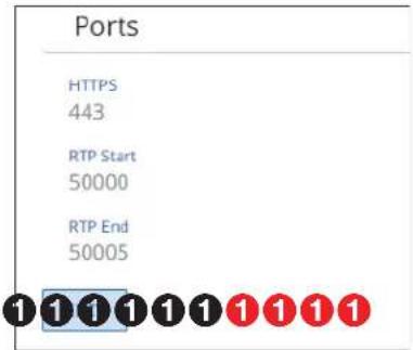
Figure 60. Ports Selection
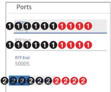
Figure 61. Editable Ports Selection
① HTTPS and RTP Start — Click in these fields and type in valid values for your encoder.
NOTES:
- Valid HTTPS values:
- = Disabled
443 = Default - 1024 - 65535 = Other available options so long as they are not overlapping on the encoder.
- Valid RTP Start values:
- θ - Disabled
• 1024 - 65529 = Free use - See the NAV Series Pro AV Ports and Licenses Guide, available at www.extron.com, for more information on ports.
② SAVE and CANCEL buttons — Click SAVE to take Port changes or CANCEL to abandon them. Clicking either button closes the editable pane.
Advanced page
On the Advanced Device Settings page (see figure 62), click the down arrow (①) to open a drop-down menu (see Advanced Networking page on page 60 and LLDP page on page 62).
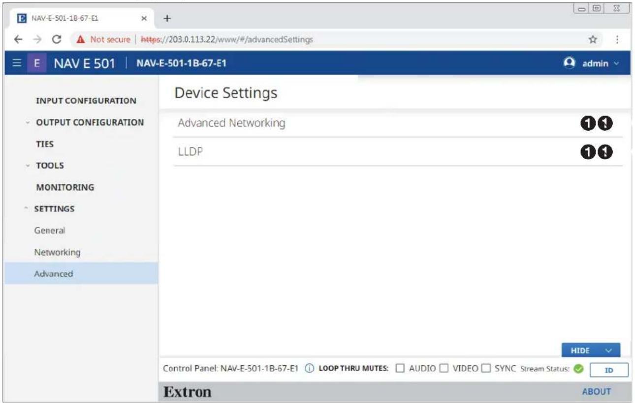
Figure 62. Advanced Settings Page
Advanced Networking page
The Advanced Networking selection on the Advanced page (see figure 62 on page 59) opens a read-only pane that shows the port usage parameters of the encoder (see figure 63). The parameters can be edited by clicking the EDIT button (1). An editable version of the selection opens (see figure 64).
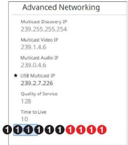
* NAV E 501 only
Figure 63. Advanced Networking Selection
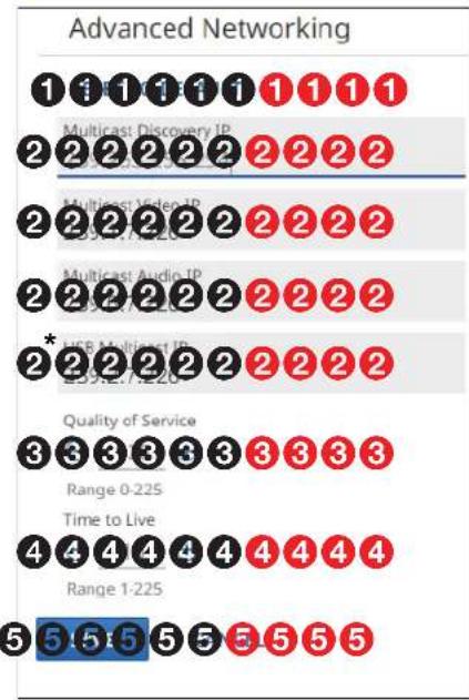
bar
Advanced Networking | Category | Count | |---|---| | Multicast Discovery IP | 1 1 1 1 1 1 1 1 1 | | Multicast Audio IP | 2 2 2 2 2 2 2 2 2 | | Multicast Video IP | 2 2 2 2 2 2 2 2 2 | | Multicast Audio IP | 2 2 2 2 2 2 2 2 2 | | UCR Multiest IP | 2 * 2 2 2 2 2 2 2 2 | | Quality of Service | 3 3 3 3 3 3 3 3 3 | | Range 0-225 | | | Time to Live | 4 4 4 4 4 4 4 4 4 4 | | Range 1-225 | | | Color: Blue (5,5,5,5,5,5,5) |* NAV E 501 only
Figure 64. Editable Advanced Networking Selection
① RESET TO DEFAULT — Click to restore the advanced networking settings of the encoder to their default values.
② Multicast IP addresses (see figure 64 on page 60) — Click in these fields and type in valid IP addresses for your encoder.
NOTES:
- Multicast Discovery IP is the multicast IP address that the encoder uses to discover and communicate with all other NAV devices on the network.
- Multicast Video IP is the IP address that outputs the NAV video stream.
- Multicast Audio IP is the IP address that outputs the NAV audio stream.
- USB Multicast IP (NAV E 501 only) is the multicast IP address that the encoder uses to send and receive the USB stream.
③ Quality of Service — This setting affects the audio and video streams only and accepts valid differentiated services code point (DSCP) type of service (TOS) decimal values to adjust the priority of the packets. Click the -and buttons or type a number into the field (within the range 0 to 225) to overwrite the factory default.
NOTE: The lower the number, the lower the priority of the packet within a queue. This may result in packet loss, latency, and jitter in a saturated link.
4 Time to Live — Click the and buttons or type a number into the field (within the range 1 to 225) to overwrite the factory default.
NOTE: Understanding how many network hops your farthest endpoint is can help assure that the packet reaches the desired destination. If too small of a value is entered, the network could discard the packet before it reaches the destination. In this case, the endpoint does not receive the streams.
⑤ SAVE and CANCEL buttons — Click SAVE to take changes or CANCEL to abandon them. Clicking either button closes the editable pane.
LLDP page
The LLDP selection on the Advanced page (see figure 62 on page 59) opens a pane that shows the status of Link Layer Discovery Protocol (on or off) and provides general extended information about the NAV AV LAN (see figure 65) and the Ethernet Extension LAN (NAV E 501 only), see figure 66 on page 63).
NOTE: For the NAV E 501 only, as necessary, click and drag the vertical scroll bar (see figure 65, A and figure 66, A) up and down to display the entire page.
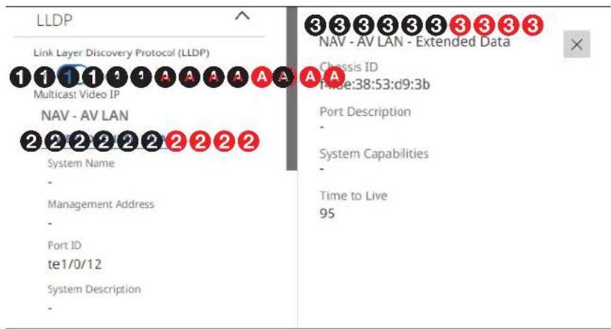
Figure 65. LLDP Page
① Link Layer Discovery Protocol (LLDP) — LLDP, a vendor-neutral protocol, is used by network devices to discovery, identify and share information between two directly connected network devices. Click to toggle LLDP on and off.
NOTES:
• ② through ⑤ (see figure 66 on page 63) are not displayed when LLDP is toggled off.
- You can only display one pane of Extended Data (③), NAV - AV LAN or Ethernet Extension (⑤), at a time.
② VIEW EXTENDED DATA button (NAV - AV LAN) — Opens a pane at the right of the page (③) that shows additional LLDP neighbor information.
③ NAV - AV LAN Extended Data pane (NAV E 501 only)—A read-only pane that provides additional, detailed, read-only LLDP information about the directly connected neighboring device on the interface. Click ✗ to close the pane.
④ VIEW EXTENDED DATA button (Ethernet Extension [NAV E 501 only], see figure 66) — Opens a pane at the right of the page (⑤) that shows your full Ethernet Extension LAN topology.
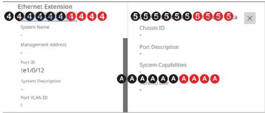
Figure 66. LLDP Page, Continued (NAV E 501 Only)
⑤ Ethernet Extension - Extended Data pane (NAV E 501 only) — A read-only pane that provides additional details of the Ethernet Extension topology. Click × to close the pane.
About Page
Access the About page by clicking ABOUT (see figure 67, ①).
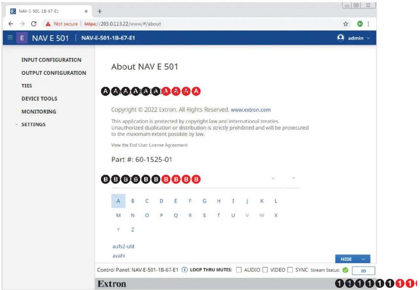
Figure 67. About Pane
The About pane provides the following useful information:
A Firmware version number, which is current NAV firmware version running.
B Installed licenses, which can be sorted by clicking the desired filtering letter.
Control System
This section includes:
- Secure Platform Device
- Toolbelt
• Global Configurator Plus and Professional - Global Scripter
The encoder can be remotely controlled from a host device such as a computer or Extron control system. The controlling device communicates over the network via the NAV/PoE+ port (see G on page 6).
Secure Platform Device
As a Secure Platform Device (SPD), the encoder is a system-based device that communicates with an Extron controller and supports 802.1X port-based Network Access Control. When applied, 802.1X authentication requires that all devices are approved before network access is granted.
The encoder communicates with compatible controllers such as Extron IPCP Pro and IPL Pro series control products over a secure, encrypted channel. The encoder hosts secure Serial and IR ports as well as a Secure Port Interface for SIS control of the encoder.
Toolbelt
The Extron Toolbelt utility is available on the Extron website. Toolbelt is a stand-alone Windows application for the management of control systems. Toolbelt can automatically discover Pro Series controllers and devices and NAV devices on a network (see the Toolbelt Help file). You also can manually add devices, using the known IP addresses. Once you log in to a NAV device, such as a NAVigator or NAV E 101, you can perform tasks such as:
- Launch the embedded encoder HTML page after discovery.
• View the device and system information.
• View and edit network information.
• View and set SSL certifications.
• Use utilities such as Ping, Reset, and Reboot. - Configure 802.1X security settings.
• View 802.1X status logs. - Update the firmware to a selected device or group of devices.
Secure Sockets Layer (SSL) Certificates
Extron NAV devices ship with factory-installed SSL certificates created by Extron. If you want or are required to use a different SSL certificate at your installation site, then you can use system utilities in the Toolbelt software to change the SSL certificate at any time. The Toolbelt Help File provides instructions on how to apply an SSL certificate to a device.
NOTES:
- You must run Toolbelt as an administrator.
- Some certificates require a passphrase that is created when the certificate is created. If a passphrase is required, you must enter that passphrase before uploading and applying the certificate.
NAV devices support standard OpenSSL certificate encodings such as .pem (Privacy-enhanced Electronic Mail) and .der (Distinguished Encoding Rules) file types. PEM file types are ASCII encoded and are the required format for uploading to the device. DER file types are binary encoded and can typically have several file extension variations, such as .crt and .cer. There are many standard tools that can convert from DER to PEM file encodings if needed.
NOTE: A DER format file must be converted to PEM encoding before uploading it to the device.
To properly create the certificate for uploading to Extron NAV devices, ensure that the certificate file meets the following requirements:
- Contains X.509 certificate information
- Contains public and private keys
- Uses PEM encoding
NOTE: ITU-T standard X.509 covers aspects of public key encryption, digital cryptography, certificates, and validation.
Contact your IT administrator for more information on what tools and policies are required to obtain or create the SSL certificate and, if necessary, the corresponding passphrase.
Global Configurator Plus and Professional
NOTE: NAV products can be used in control systems with the following Extron control products:
- IPCP Pro Processors such as the IPCP Pro 250
- IPL Pro Control Processors such as the IPL Pro S3
Global Configurator is an Extron control system configuration software for use in AV systems that include Extron Pro Series control products. Conditional logic, variables, and macros provide flexibility for elaborate control system designs. No direct programming knowledge is needed to use the program.
The functional logic is built into Global Configurator. You merely select the functions that you want to use. You can quickly set up schedules, macros, monitors, and the like, using available actions and commands, without having to write control script.
Global Configurator has two modes:
- Global Configurator Plus — Ideal for smaller applications requiring one control processor and one control interface.
- Global Configurator Professional — Suited for applications requiring multiple control processors, enhanced functionality, and advanced configuration. Access to Global Configurator Professional requires ECP Certification.
In a NAV system with an Extron controller, such as an IPCP Pro 250, you can perform actions such as:
- Load device drivers for monitoring the status of and controlling devices with the NAV system.
- Upload GUI Designer interface layouts to touchpanels and third-party touch interfaces.
- Create the configuration containing all the settings for the control processor and the products with which it interacts in the NAV system.
- Upload the configuration to the control processor.
- Send limited commands (such as some SIS commands) via the controller to a NAV device (but without receiving a response from the device).
To obtain Extron control product software, you must have an Extron Insider account and contact an Extron support representative on the Extron S3 Sales and Technical Support Hotline (see www.extron.com for the phone number in your region of the world). Extron provides training to our customers on how to use the software. Access to the features of Global Configurator Professional is available to users who successfully complete Extron Control Professional Certification.
For detailed descriptions and procedures to setup a control system with an IPCP Pro device and Global Configurator, see the applicable Global Configurator Help File.
Global Scripter
NOTE: NAV products can be used in control systems with the following Extron control products:
- IPCP Pro Processors such as the IPCP Pro 250
- IPL Pro Control Processors such as the IPL Pro S3
Global Scripter is a powerful and versatile control system programming software from Extron for AV systems that use an Extron Pro series control processor (such as an IPCP Pro 250). Global Scripter, being programming (rather than just configuration) software, is much more flexible than Global Configurator. Global Scripter allows an integrator to write customized programs for his or her specific AV system. Using customized programming commands for configuration and control allows for larger AV systems than Global Configurator.
Global Scripter uses the easy-to-learn Python scripting language and includes the Extron-exclusive Python library: ControlScript. ControlScript increases the productivity of AV programmers by incorporating functions used in common AV control system projects, as well as helpful documentation, reference material, and sample code. Global Scripter can insert specific AV devices (such as SPDs) and functions into the code.
In a NAV system with an Extron controller, such as an IPCP Pro 250, you can support many more devices (system controllers, NAVigators, and endpoints) than Global Configurator, send very specific SIS commands (as programmed code) and get feedback.
NOTE: Global Scripter software users and integrators other and must know how to program with Python and should know how to use Extron ControlScript.
For detailed descriptions and procedures to setup a control system with an IPCP Pro device and Global Scripter, see the Global Scripter Help File.
SIS Operation
The encoder can be remotely controlled, monitored, or configured using the following:
- A user-defined string consisting of SIS commands (see below)
NOTE: SIS commands cannot be issued directly to the encoder, but are issued via an Extron control system on the AV network using a process known as “encapsulation”.
- Extron Toolbelt or a control system constructed using either Global Configurator Plus, Global Configurator Pro, or Global Scripter (see Control System on page 65)
• Built-in HTML pages (see HTML Operation on page 16)
This section provides guidance on operation of the encoder via a string of commands and lists the SIS commands, including:
• Host-to-Encoder Communications
• Encoder-Initiated Messages
• Encoder Error Responses
• Using the Command and Response Tables
• SIS Command and Response Table
Host-to-Encoder Communications
SIS commands consist of one or more characters per field. No special characters are required to begin or end a command character sequence. When a command is valid, the encoder executes the command and sends a response to the host device. All responses from the encoder to the host end with a carriage return and a line feed (CR/LF = ←), which signals the end of the response character string. A string is one or more characters.
Encoder-Initiated Messages
When the encoder completes its start-up, it issues the following message to the host:
© Copyright 20yy, Extron Electronics NAV E n01, Vx.xx, 60-nnnn-nn← (n = 5 or 1)
Vx.xx is the firmware version number and 60-nnnn-nn is the part number.
Hplgl
The HDMI input hot plug connection is changed. 1 is plugged and 0 is unplugged.
HplgO
The HDMI loop through hot plug connection is changed. 1 is plugged and is unplugged.
In
A change in signal input status has occurred. 1 is input detected and 0 is no input.
Encoder Error Responses
When the encoder receives a valid SIS command, it executes the command and sends a response to the host device. If the encoder is unable to execute the command because the command is invalid or it contains invalid parameters, the encoder returns an error response to the host. The error response codes are:
E10 — Invalid command
E12 — Invalid port number
E13 — Invalid parameter
E14 — Invalid for this port configuration
E17 — Invalid command for signal type
E22 — Busy
E24 — Privilege violation
E25 — Device not present
E28 — Bad file name or file not found
The command operation is aborted with no other indication.
Using the Command and Response Tables
The command and response tables begin on page 71. Symbols are used throughout the table to represent variables in the command and response fields. Command and response examples are shown throughout the table. The ASCII to HEX conversion table below is for use with the command and response table.
| Space → | ASCII to | Hex | Conversion Table | Esc | 1B | CR | ØD | LF | ØA | ||||||
| 20 | ! | 21 | " | 22 | # | 23 | $ | 24 | % | 25 | & | 26 | ' | 27 | |
| ( 28 ) | 29 | * | 2A | + | 2B | , | 2C | - | 2D | • | 2E | / | 2F | ||
| Ø 30 | 1 | 31 | 2 | 32 | 3 | 33 | 4 | 34 | 5 | 35 | 6 | 36 | 7 | ||
| 8 38 | 9 | 39 : | 3A : | 3B ; | 3B < | 3C = | |||||||||
| @ 40 | A | 41 B | 42 B | C K | |||||||||||
| H 48 | I 49 J | 4A K | |||||||||||||
| P 50 Q | 51 R | 52 S | |||||||||||||
| X 58 Y | 59 Z | 5A [ | |||||||||||||
| ` 60 a | 61 b | 62 c | |||||||||||||
| h 68 i | 69 j | 6A k | |||||||||||||
| p 70 q | 71 r | 72 s | |||||||||||||
| x 78 y | 79 z | 7A { } | |||||||||||||
Common symbol definitions
← = Carriage return/line feed
← = Carriage return (no line feed)
| = Pipe (can be used interchangeably with the character)
- = space
Esc = Escape key
W = Can be used interchangeably with the Esc character
SIS Command and Response Tables
Command and Response Table for Encoder Commands
| Command Function | SIS Command (Host to Unit) | Response (Unit to Host) | Additional description |
| HDCP authorized device | |||
| Set input to HDCP authorized | EscE1HDCP← | HdcpE1← | Default. HDCP Authorized is used to bar an HDCP encrypted source into the HDMI Input. |
| Set input to HDCP not authorized | EscE0HDCP← | HdcpE0← | |
| View HDCP authorized status | EscEHDCP← | X1← | |
| Input signal status | |||
| View input signal status | Esc0LS← X1← | ||
| USB mode (NAV E 501 only, valid as USB host or USB device) | |||
| NOTES:You can tie a USB host only to a USB device for proper system operation.If you connect a host such as a PC to an endpoint that is in USB device mode, the endpoint cannot recognize the device. | |||
| View encoder USB mode | EscMUSBC← | X3← | |
| USB tie (NAV E 501 only, valid in device mode only) | |||
| NOTE: If the encoder is in host mode or off, it returns an E14 error in response to the tie, untie, and view tie commands. | |||
| Tie encoder to USB host | EscX6X7← | InX6X7•Usb← | |
| Untie USB | Esc0i← | In0i•Usb← | The untie command is always Esc0i^, even for an encoder. |
| View USB tie | ^ | X31← | |
| USB status (NAV E 501 only) | |||
| View host status | EscIUSBC← | Usbc1X1← | |
| View device status | Esc0USBC← | UsbcdX1← | |
| Streaming control | |||
| Set video stream on | EscV1STRC← | StrcV1← | Default. |
| Set video stream off | EscV0STRC← | StrcV0← | |
| Set audio stream on | EscA1STRC← | StrcA1← | Default. |
| Set audio stream off | EscA0STRC← | StrcA0← | |
| View video stream | EscVSTRC← X1← | ||
| View audio stream | EscASTRC← X1← | ||
| Streaming bit rate | |||
| Set streaming rate | EscVX2BITR← | BitrVX2← | |
| Show bit depth mode | EscVBITR← X2← | ||
| Video mute (HDMI LOOP THRU port) | |||
| Mute video only | 1B | Vmt1← | |
| Mute video and sync | 2B | Vmt2← | |
| Unmute video and sync | 0B | Vmt0← | Default. Video output is active. |
| Show mute status | B | X3← | |
| KEY:X1= Status θ = Off, disabled, not detected 1 = On, enabled, detectedX2= Streaming rate or bandwidth (in Mbps) 150 - 900 (default = 850)X3= Video mute status θ = Unmute 1 = Mute video 2 = Mute video and syncX4= Audio routing θ = Auto (default) 1 = Digital (HDMI) input 2 = Analog inputX5= USB mode θ = Off 1 = Host 2 = DeviceX6= USB host I/O Number:ororX7= Encoder (input) or decoder (output) Only first letter (i or o) is valid.Audio routing selection | |||
| Select digital (HDMI) audio input | EscI1AFMT← | AfmtI1← | |
| Select analog audio input | EscI2AFMT← | AfmtI2← | |
| Select auto audio selection | EscI0AFMT← | AfmtI0← | Default. Digital input takes priority. |
| View input audio selection | EscIAFMT←X4← | ||
| Audio mute (HDMI LOOP THRU port) | |||
| Mute audio | 1*1Z | Amt1*1← | |
| Unmute audio | 1*0Z | Amt1*0← | Default. Audio output is active. |
| View audio mute status | 1Z | X1← | Audio mute status is X1. |
| Reset | |||
| Reset to factory setting | EscZQQQ← | Zpq← | Reset to factory defaults. Firmware version remains the same. |
| Device name | |||
| Set device name | EscX8CN← | Ipn•X8← | |
| Read device name | EscCN←X8← | ||
| Reset device name to factory default | Esc•CN← | Ipn•NAV-E-n01-←(n=5 or 1) | |
| Device tags | |||
| View device tags | EscDTAG←X9← | ||
| Device number | |||
| View device number | EscDNUM←X10← | ||
| Information requests | |||
| Information request | I | SigIX1•HdcpIX11•Hdcp0X11•ResIX12•AudiIX13•StrmIX14•LnkX14•Enc← | |
| Response description: | Input signal•Input HDCP•Output HDCP•Resolution•Input audio•Streaming•Link•Encoder← | ||
| Example: | I | SigI1•HdcpI2•Hdcp02•ResI1920x1080@60 Hz•AudiO•StrmI1•Lnk1•Enc← | An input signal is detected, the input and output are HDCP devices, the resolution is 1920x1080@60 Hz, the digital audio input is selected, streaming and link are active, and the device is an encoder. |
| View model name | 1I | NAV•E•n01← | n=5 or 1. |
| View model description | 2I | NAV•Gigabit•Encoder•HDMI← | |
| View number of connected users | 10I | X15← | |
| View input video format | 34I | X16← | |
| View HDCP input status | 35I | X11← | |
| View audio input selection | 36I | X13← | |
| View streaming status | 37I | X14← | |
| View HDCP output status | 38I | X11← | |
| KEY: X1 = Status θ = Off, disabled, not detected 1 = On, enabled, detectedX4 = Audio routing θ = Auto (default) 1 = Digital (HDMI) input 2 = Analog inputX8 = Name A text string of up to 63 alphanumeric characters and minus sign/hyphen (-).No blank or space characters are permitted as part of a name.The first character must be a letter, and the last character must not be a minus sign/hyphenX9 = Tag A list of text tags returned in a json stringX10 = Device number 0001 - 4096X11 = HDCP status θ = No device 1 = Non-HDCP device 2 = HDCP deviceX12 = Resolution and rate in plain text Example: 1920x1080@60 Hz)X13 = Audio input selected θ = Digital 1 = AnalogX14 = Streaming and link status θ = No link 1 = Active 2 = Active with errorsX15 = Number of connected users θ = 1X16 = Input video format θ = Not detected 1 = HDMI 2 = DVIInformation requests, continued | |||
| View connected video streams | 39I | X17←X17←●●←●●←X17←← | Show all (n) connected video streams. |
| Example: | 39I | Conf Rm 1, 192.168.254.254, 239.199.188.175←Conf Rm 2, 192.168.254.253, 239.199.188.165←●●●←Class Rm 5, 192.168.254.252, 239.199.188.155←← | |
| View connected audio streams | 40I | X17←X17←●●←●●←X17←← | Show all (n) connected audio streams. |
| View average bandwidth | 41I | X2← | |
| View current total bandwidth | 42I | X2← | |
| View current video bandwidth | 43I | X2← | |
| View current audio bandwidth | 44I | X2← | |
| View network status | 46I | X14← | |
| View dropped packets | 48I | X18← | |
| View IGMP querier | 50I | X19← | |
| View device serial number | 98I | X20← | |
| View internal temperature | Esc20STAT←X21← | ||
| Firmware version | |||
| Read firmware version | Q | X22← | |
| Read full firmware version | *Q | X23← | |
| Read full firmware version — Advanced | 20Q | X24← | |
| Part number | |||
| View part number | N | 60-xxxx-xx← | |
| KEY: X2 = Streaming rate or bandwidth (in Mbps) 150 - 900 (default = 850)X14 = Streaming and link status θ = No link 1 = Active 2 = Active with errorsX17 = Connected streams, | |||
Command and Response Table for IP-Specific SIS Commands
| Command Function | SIS Command (Host to Unit) | Response (Unit to Host) | Additional description |
| DHCP client | |||
| Set DHCP on | Esc1*1DHCP← | Dhcp•1*1← | |
| Set DHCP off | Esc1*0DHCP← | Dhcp•1*0← | |
| View DHCP status | Esc1DHCP←X1← | ||
| IP address | |||
| Set IP address | EscX19CI← | IpiX19← | |
| View IP address | EscCI←X19← | ||
| Subnet mask | |||
| Set subnet mask | EscX19CS← | IpsX19← | |
| View subnet mask | EscCS←X19← | ||
| Gateway address | |||
| Set gateway address | EscX19CG← | IpgX19← | |
| View gateway address | EscCG←X19← | ||
| DNS address | |||
| Set DNS address | EscX19DI← | IpdX19← | |
| View DNS address | EscDI←X19← | ||
| IP address | |||
| Set IP address | Esc1*X19CISG← | Cisg•1*X19← | |
| IP and subnet mask | |||
| Set IP address and subnet mask | Esc1*X19IP*X19SubsetCISG← | Cisg•1*X19P/X25Subset+X19Gateway← | |
| Set IP address and subnet mask | Esc1*X19IP/X25SubsetCSIG← | Cisg•1*X19P/X25Subset+X19Gateway← | |
| IP, Subnet, and gateway address all at once | |||
| Set IP address, subnet address, and gateway | Esc1*X19IP*X19SubsetCISG← | Cisg•1*X19P/X25Subset+X19Gateway← | |
| Set IP address, subnet address, and gateway | Esc1*X19IP/X25SubsetCISG← | Cisg•1*X19P/X25Subset+X19Gateway← | |
| View IP address, subnet address, and gateway | Esc1*CISG←X19 | IP/X25Subset*X19Gateway← | |
| MAC address | |||
| View MAC address | EscCH← | X26← | |
| KEY: X1= Status θ = Off, disabled, not detected 1 = On, enabled, detectedX19= IP address, subnet, gateway address xxx.xxx.xxx.xxxX25= Subnet prefix Number of bits used to create the subnetX26= MAC address xx-xx-xx-xx-xx-xx | |||
Troubleshooting
Alarms
The following table lists common NAV alarms shown on the Monitoring page (see Alarms pane on page 45) and suggested remedies:
| Alarm Cause Remedy | ||
| Assignment Conflict | The endpoint is reporting a conflicting assignment status. | Verify that the endpoint is not assigned to another NAVigator. If it is, it must be unassigned from the previous NAVigator. If the previous NAVigator is unavailable, perform a mode 5 reset (see page 14) on the conflicted endpoint. |
| Assignment Failure | The endpoint failed to be assigned to a NAVigator. | Confirm that the NAVigator has not reached its endpoint assignment limit. If a device has been decommissioned from the NAV system, unassign the endpoint from the "Offline endpoints" list. If endpoint still cannot be assigned, perform a mode 5 reset on the endpoint. |
| Audio Loss | The input audio signal level is below -60 dB for a period of 5 minutes or more. | Increase the output level of audio source. |
| Auth Failures | A user has attempted to login unsuccessfully 10 or more times. | Check whether login attempts were from internal personnel. If not, take action to strengthen security measures. |
| Backup Restore Failure | A problem occurred while trying to perform a backup or a restore. | Debug network connectivity between the NAVigator and endpoints. |
| Channel Conflict | Two or more NAV devices on the network have been given the same input or output number. | For devices affected, change the input number or output number so that each is unique to encoders in the system. |
| Communication Failure | An online assigned endpoint cannot establish a connection with the NAVigator. | Check the network settings to ensure unicast routing is possible between the NAVigator and endpoints. |
| Controller Disconnect | The NAV device is unable to connect to a paired control processor. | Verify the control processor is online. Review network settings to ensure unicast communication is possible from the NAV device to the control processor. |
| CPU Usage | The NAV device CPU is overloaded. Check for excessive network data being delivered to the endpoint. | |
| Device Offline | An assigned NAVigator is not discovered on the network. | Check the offline NAVigator for a power failure. Check the network connectivity of the endpoint. |
| Disk Space | Internal storage on the NAV device is low. | Reboot the NAV device. If the issue persists, perform a software reset that deletes files (see RESET tab on page 39). |
| Firmware Failure | A critical process has failed, crashing the endpoint. | Reboot the NAV device. If the failure persists, perform a mode 1 reset (see Reset Operations on page 14). |
| Firmware Incompatible | A firmware version discrepancy exists between the NAVigator and assigned endpoints. | Upgrade the firmware on the deviating device. |
| Firmware Upgrade | The firmware upgrade process on NAVigator or endpoints failed to complete. | Retry the firmware upgrade. If it is again unsuccessful, use Toolbelt or a web browser to directly manage the device and perform a unit firmware upgrade. |
| HDCP Error | Encoder: The video input signal is HDCP protected and HDCP negotiation has failed.Decoder: The incoming stream is HDCP protected and the display connected to the output does not support HDCP or the HDCP version. | Encoder:Disconnect and reconnect the video input cable into the encoder.Bypass video adapter cables and make a direct HDMI male-to-male connection.Decoder: Check the technical specifications of the display that is connected to the decoder for HDCP version support. |
| IGMP Failure | The NAV device failed to receive three consecutive IGMP queries from an IGMP querier. | Debug network connectivity between the NAV device and the IGMP querier (which can be either a router or a managed switch). |
| Link Speed | The negotiated communication speed (Link Speed) between the NAV device and a managed switch is lower than its capability of 1 Gbps. | Check switch configuration and ensure proper settings for the switch port to which the NAV device is connected. |
| Name Conflict | Two or more NAV devices on the network have the same device name. | Change the device names affected so that each is unique. |
| Network Conflict | Two or more NAV devices on the network have the same IP address. | Change the IP addresses affected so that each is unique. |
| Network Utilization | The NAV device is receiving excessive network traffic. | Check the network for flooding, also check for improper network configuration. |
| NTP Sync | The NAVigator cannot obtain time from the specified NTP server. | Debug the network connectivity between the NAVigator and the specified NTP server. |
| PTP Master Stability | The clock to which all devices are synchronized is changing too frequently, for example, due to network jitter. | Check network for flooding and correct PTPv2 packet priority. |
| PTP Sync | NAV device cannot synchronize its PTPv2 clock with any peers. | Ensure that network policies allow PTPv2 packets to reach the NAV Device from a clock master. |
| Stream Conflict | Multiple NAV endpoints are configured to use the same video, audio, AES67, or USB multicast IP address. | Reconfigure endpoint stream settings for a unique stream address. |
| Stream error | NAV E 501 in Device mode only — The encoder has lost reception of the USB stream for 2 seconds or more. | Check all network switches and routers that support your NAV system for proper multicast (IGMP) configuration. |
| Temperature Internal | The NAV device is overheating. Check the | ambient temperature of the NAV device installation location.If greater than 104°F, (60°C) use HVAC system to lower ambient temperature.If ambient temperature is 104°F, (60°C) or less, check the mounting location for nearby equipment emitting excessive heat.Ensure there is an air gap around endpoint to allow adequate airflow. |
| Tie Failure | The encoder failed to establish a tie with the specified endpoint. | Debug the network connectivity between the encoder and decoder. |
| USB Over-current | NAV E 501 in Device mode only — One or more USB devices connected exceeded power budget (500 mA). | Remove one or more USB devices that caused the over-current. |
| Video loss | The input is changed and video sync cannot be established within a two-second window. | Debug the connectivity of the A/V source device to the NAV encoder. |
Reference Information
Mounting the Encoder
ATTENTION:
The 1-inch high, half-rack width encoder can be placed on a table, mounted in a rack, or mounted under a desk or table.
Tabletop Use
Affix the included rubber feet to the bottom of the unit and place it in any convenient location.
Mounting kits
Mount the unit using any optional compatible mounting kit listed on the Extron website (www.extron.com), in accordance with the directions included with the kit.
ATTENTION:
For rack mounting, see UL Rack-Mounting Guidelines on page 79.
UL Rack-Mounting Guidelines
The following Underwriters Laboratories (UL) requirements pertain to the installation of the unit into a rack.
CAUTION:
- Elevated operating ambient temperature — If installed in a closed or multi-unit rack assembly, the operating ambient temperature of the rack environment may be greater than room ambient. Therefore, consider installing the equipment in an environment compatible with the maximum ambient temperature (TMA = +104°F, +40°C) specified by Extron.
- Reduced air flow — Installation of the equipment in a rack should be such that the amount of air flow required for safe operation of the equipment is not compromised.
- Mechanical loading — Mounting of the equipment in the rack should be such that a hazardous condition is not achieved due to uneven mechanical loading.
- Circuit overloading — Consideration should be given to the connection of the equipment to the supply circuit and the effect that overloading of the circuits might have on overcurrent protection and supply wiring. Appropriate consideration of equipment nameplate ratings should be used when addressing this concern.
- Reliable earthing (grounding) — Reliable earthing of rack-mounted equipment should be maintained. Particular attention should be given to supply connections other than direct connections to the branch circuit (such as use of power strips).
Extron warrants this product against defects in materials and workmanship for a period of three years from the date of purchase. In the event of malfunction during the warranty period attributable directly to faulty workmanship and/or materials, Extron will, at its option, repair or replace said products or components, to whatever extent it shall deem necessary to restore said product to proper operating condition, provided that it is returned within the warranty period, with proof of purchase and description of malfunction to:
USA, Canada, South America, and Central America:
Extron
1230 South Lewis Street
Anaheim, CA 92805
U.S.A.
Asia:
Extron Asia Pte Ltd
135 Joo Seng Road, #04-01
PM Industrial Bldg.
Singapore 368363
Singapore
Japan:
Extron Japan
Kyodo Building, 16 Ichibancho
Chiyoda-ku, Tokyo 102-0082
Japan
Europe:
Extron Europe
Hanzeboulevard 10
3825 PH Amersfoort
The Netherlands
China:
Extron China
686 Ronghua Road
Songjiang District
Shanghai 201611
China
Middle East:
Extron Middle East
Dubai Airport Free Zone
F13, PO Box 293666
United Arab Emirates, Dubai
Africa:
Extron South Africa
3rd Floor, South Tower
160 Jan Smuts Avenue
Rosebank 2196, South Africa
This Limited Warranty does not apply if the fault has been caused by misuse, improper handling care, electrical or mechanical abuse, abnormal operating conditions, or if modifications were made to the product that were not authorized by Extron.
NOTE: If a product is defective, please call Extron and ask for an Application Engineer to receive an RA (Return Authorization) number. This will begin the repair process.
USA: 714.491.1500 or 800.633.9876 Asia:
65.6383.4400
Europe: 31.33.453.4040 or 800.3987.6673
Japan: 81.3.3511.7655
Africa: 27.11.447.6162
Middle East: 971.4.299.1800
Units must be returned insured, with shipping charges prepaid. If not insured, you assume the risk of loss or damage during shipment. Returned units must include the serial number and a description of the problem, as well as the name of the person to contact in case there are any questions.
Extron makes no further warranties either expressed or implied with respect to the product and its quality, performance, merchantability, or fitness for any particular use. In no event will Extron be liable for direct, indirect, or consequential damages resulting from any defect in this product even if Extron has been advised of such damage.
Please note that laws vary from state to state and country to country, and that some provisions of this warranty may not apply to you.
- NAV E 501 and NAV E 101
- Safety Instructions
- Safety Instructions • English
- ATTENTION:
- FCC Class A Notice
- NOTES:
- Battery
- Conventions Used in this Guide
- Notifications
- Software Commands
- Specifications Availability
- Extron Glossary of Terms
- Contents
- Introduction ...... 1
- Installation and Basic Operation .... 5
- HTML Operation....16
- Control System...... 65
- SIS Operation 69
- Troubleshooting 75
- Reference Information 78
- Introduction
- About this Guide
- About the NAV System
- About the Encoder
- About the Decoder
- System Interaction and Capabilities
- Features
- Installation and Basic Operation
- Mounting
- Connector and Cable Details
- HDMI connectors
- Lockit Lacing Brackets
- Analog audio connectors
- Control connector wiring
- TP cable termination
- Power supply wiring
- CAUTION:
- ATTENTION :
- Startup and Basic Operation
- Power
- Pairing Devices Manually
- Operation
- System operation with a NAVigator
- Configuration and other operations
- Reset operations
- Performing mode 4 and 5 resets
- HTML Operation
- Opening the Embedded HTML Pages
- Using the HTML Pages
- Input Configuration Page
- Video pane
- Audio Pane
- Output Configuration Page
- Stream pane
- Loop Thru pane
- Test Pattern pane
- AES67 pane
- AES67 Audio Configuration
- Figure 20. AES67 Pane
- Screen Saver pane
- Upload a custom image
- On Screen Display (OSD) pane
- Ties Page
- Current Input pane
- Available Outputs pane
- Tools Pages
- BACKUP tab
- RESTORE tab
- FIRMWARE tab
- Click UPDATE (2).
- RESET tab
- Click APPLY (4).
- Diagnostic Tools page
- Monitoring Page
- IGMP Querier pane
- Ethernet Extension Utilization pane (NAV E 501 only)
- USB Devices pane (NAV E 501 only)
- Primary Controller pane
- Alarms pane
- Download Logs
- Settings Pages
- General page
- Device Details page
- Date & Time page
- Sync time with server —
- Username/Password page
- USB page (NAV E 501 only)
- Networking page
- Network Connection page
- Network Connection
- Ports page
- Advanced page
- Advanced Networking page
- LLDP page
- About Page
- Control System
- Secure Platform Device
- Toolbelt
- Secure Sockets Layer (SSL) Certificates
- Global Configurator Plus and Professional
- Global Scripter
- SIS Operation
- Host-to-Encoder Communications
- Encoder-Initiated Messages
- Encoder Error Responses
- Using the Command and Response Tables
- Common symbol definitions
- SIS Command and Response Tables
- Troubleshooting
- Alarms
- Reference Information
- Mounting the Encoder
- Tabletop Use
- Mounting kits
- UL Rack-Mounting Guidelines
- USA, Canada, South America, and Central America:
- Asia:
- Japan:
- Europe:
- China:
- Middle East:
- Africa:
Brand : Extron
Model : NAV E 101
Category : Electronics