
FOXBOX T HD-SDI - Electronics Extron - Free user manual and instructions
Find the device manual for free FOXBOX T HD-SDI Extron in PDF.


| Product Type | HD-SDI Fiber Optic Transmitter |
| Brand | Extron |
| Model | FOXBOX T HD-SDI |
| Dimensions (H x W x D) | 1.7 in x 4.3 in x 3.0 in (4.3 cm x 10.9 cm x 7.6 cm) |
| Weight | 0.5 lb (0.23 kg) |
| Power Supply | 12 V DC, 5 W, external power supply included |
| Input Connector | 1 x BNC female for HD-SDI |
| Output Connector | 1 x LC fiber optic connector |
| Supported Video Formats | HD-SDI (SMPTE 292M) up to 1080p |
| Fiber Type | Single-mode or multimode (SFPs optional) |
| Maximum Distance | Up to 10 km (single-mode) |
| LED Indicators | Power, Signal, Link |
| Chassis Type | Metal enclosure, desk or rack-mountable |
| Operating Temperature | 32°F to 122°F (0°C to 50°C) |
| Storage Temperature | -40°F to 158°F (-40°C to 70°C) |
| Recommended Cleaning | Wipe with dry cloth; avoid liquids |
| Safety Certifications | CE, FCC Class A |
| Included Accessories | Power supply, mounting brackets, user manual |
| Warranty | 3 years parts and labor |
| Repairability | No user-serviceable parts; contact Extron support |
Frequently Asked Questions - FOXBOX T HD-SDI Extron
User questions about FOXBOX T HD-SDI Extron
0 question about this device. Answer the ones you know or ask your own.
Ask a new question about this device
Download the instructions for your Electronics in PDF format for free! Find your manual FOXBOX T HD-SDI - Extron and take your electronic device back in hand. On this page are published all the documents necessary for the use of your device. FOXBOX T HD-SDI by Extron.
USER MANUAL FOXBOX T HD-SDI Extron
Fiber Optic Extenders
FOXBOX T HD-SDI
Fiber Optic 3G/HD/SDI Video Transmitter

Safety Instructions
Safety Instructions • English
WARNING: This symbol, when used on the product, is intended to alert the user of the presence of uninsulated dangerous voltage within the product's enclosure that may present a risk of electric shock.
ATTENTION: This symbol, when used on the product, is intended to alert the user of important operating and maintenance (servicing) instructions in the literature provided with the equipment.
For information on safety guidelines, regulatory compliances, EMI/EMF compatibility, accessibility, and related topics, see the Extron Safety and Regulatory Compliance Guide, part number 68-290-01, on the Extron website, www.extron.com.
Chinese Traditional (繁體中文)
This equipment has been tested and found to comply with the limits for a Class A digital device, pursuant to part 15 of the FCC rules. The Class A limits provide reasonable protection against harmful interference when the equipment is operated in a commercial environment. This equipment generates, uses, and can radiate radio frequency energy and, if not installed and used in accordance with the instruction manual, may cause harmful interference to radio communications. Operation of this equipment in a residential area is likely to cause interference. This interference must be corrected at the expense of the user.
Copyright
© 2015 Extron Electronics. All rights reserved.
Trademarks
All trademarks mentioned in this guide are the properties of their respective owners.
The following registered trademarks ^® , registered service marks ^(SM) , and trademarks ^(TM) are the property of RGB Systems, Inc. or Extron Electronics:
| Registered Trademarks ^(®) |
| AVTrac, Cable Cubby, CrossPoint, eBUS, EDID Manager, EDID Minder, Extron, Flat Field, GlobalViewer, Hideaway, Inline, IP Intercom, IP Link, Key Minder, LockIt, MediaLink, PlenumVault, PoleVault, PowerCage, Pure3, Quantum, SoundField, SpeedMount, SpeedSwitch, System INTEGRATOR, TeamWork, TouchLink, V-Lock, VersaTools, VN-Matrix, VoiceLift, WallVault, WindoWall, XTP, and XTP Systems |
| Registered Service Mark ^(SM) : S3 Service Support Solutions |
| Trademarks ^(TM) |
| AAP, AFL (Accu-Rate Frame Lock), ADSP (Advanced Digital Sync Processing), Auto-Image, CableCover, CDRS (Class D Ripple Suppression), DDSP (Digital Display Sync Processing), DMI (Dynamic Motion Interpolation), Driver Configurator, DSP Configurator, DSVP (Digital Sync Validation Processing), DTP, eLink, EQIP, FastBite, FlexOS, FOXBOX, Global Configurator, IP Intercom HelpDesk, LinkLicense, MAAP, MicroDigital, ProDSP, QS-FPC (QuickSwitch Front Panel Controller), Scope-Trigger, ShareLink, SIS, Simple Instruction Set, Skew-Free, SpeedNav, Triple-Action Switching, WebShare, XTRA, ZipCaddy, ZipClip |
Class 1 Laser Product
Any service to this product must be carried out by Extron Electronics and its qualified service personnel.
NOTE: For more information on safety guidelines, regulatory compliances, EMI/EMF compatibility, accessibility, and related topics, see the “Extron Safety and Regulatory Compliance Guide” on the Extron website.
Conventions Used in this Guide
Notifications
The following notifications are used in this guide:
WARNING: Potential risk of severe injury or death.
CAUTION: Risk of minor personal injury.
NOTE: A note draws attention to important information.
Software Commands
Commands are written in the fonts shown here:
^ARMerge Scene,,0p1 scene 1,1 ^B51 ^W^C [∅1] R∅0∅4∅03∅0∅04∅0∅08∅0∅06∅0 [∅2] 35 [17] [∅3]
Esc X1 * X16 * X18 * X23 * X21 CE ←
NOTE: For commands and examples of computer or device responses mentioned in this guide, the character "∅" is used for the number zero and "0" is the capital letter "o."
Computer responses and directory paths that do not have variables are written in the font shown here:
Reply from 208.132.180.48: bytes=32 times=2ms TTL=32
C:\Program Files\Extron
Variables are written in slanted form as shown here:
ping xxx.xxx.xxx.xxx -t SOH R Data STX Command ETB ETX
Specifications Availability
Product specifications are available on the Extron website, www.extron.com.
Contents
Introduction ...... 1
About this Guide....1
About the FOXBOX T HD-SDI Transmitter.....1
System Compatibility 2
Features 3
Installation and Operation 4
Connections and Features....4
Rear Panel....4
Front Panel 8
Indications and Operation....9
Indications....9
Operation 9
Programming Guide....10
Configuration Port 10
Host-to-Transmitter Communications 10
Unit-initiated Messages 10
Error Responses....11
Timeout....11
Using the Command and Response Table...... 11
Symbol Definitions 11
Equipment Mounting 15
Mounting the Transmitter 15
Tabletop Use 15
Mounting kits....15
UL Rack-Mounting Guidelines 15
Introduction
WARNING: The FOXBOX T HD-SDI outputs continuous invisible light (Class 1 rated), which may be harmful to the eyes; use with caution.
- Do not look into the rear panel fiber optic cable connectors or into the fiber optic cables themselves.
- Plug the attached dust cap into the optical transceiver when the fiber optic cable is unplugged.
This guide describes how to install, operate, and configure the following Extron FOXBOX T HD-SDI fiber optic transmitters.
- FOXBOX T HD-SDI SM — A singlemode, very long distance (up to 30 km [18.75 miles]) transmitter.
FOXBOX T HD-SDI MM — A multimode, long distance (2 km [6,561 feet]) transmitter.
NOTE: The two products are physically and functionally identical, with the exception of the effective range of transmission. The term “transmitter” refers to either product.
About the FOXBOX T HD-SDI Transmitter
The FOXBOX T HD-SDI transmits 3G HD-SDI, HD-SDI, and SDI video and embedded digital audio via a single fiber optic cable (see figure 1, on the next page). A compatible Extron fiber optic receiver receives the image and outputs the video and audio. The transmitter can also send, on the same fiber optic cable:
- Optional analog audio
• RS-232 control signals
With a second fiber optic cable, the transmitter can receive RS-232 responses from the connected receiver.
NOTE: The RS-232 communications are a passive pass-through only. The transmitter does not generate or respond to the RS-232 communication signals.

flowchart
graph TD
    A["PTZ Camera"] -->|3G-SDI| B["Extron FOXBOX T HD-SDI Fiber Optic Transmitter"]
    B -->|RS-232| C["Extron IPCP Pro 250 IP Link Pro Control Processor"]
    C -->|Ethernet| D["TCP/IP Network"]
    D -->|Ethernet| E["Extron FOXBOX SR HDMI Fiber Optic Receiver"]
    E -->|HDMI| F["Display"]
    C -->|RS-232| G["Extron TLP Pro 1020T 10" Tabletop TouchLink Pro Touchpanel"]
    G -->|Ethernet| H["Display"]
    style A fill:#f9f,stroke:#333
    style B fill:#ccf,stroke:#333
    style C fill:#cfc,stroke:#333
    style D fill:#fcc,stroke:#333
    style E fill:#cff,stroke:#333
    style F fill:#ffc,stroke:#333
    style G fill:#fcc,stroke:#333
    style H fill:#ffc,stroke:#333
Figure 1. Typical FOXBOX T HD-SDI Application
System Compatibility
The FOXBOX T HD-SDI is compatible with all FOX matrix switchers and the following receivers and accessory products.
The transmitter supports Plus or Non-Plus mode transmission for compatibility with FOX receivers.
- Non-Plus mode transmission — Supports resolutions from 480i up to 1080p at 60 Hz. Embedded audio is not supported, but analog audio is supported.
- Plus mode transmission — Supports all of the resolutions in non-plus mode, in addition to 2048x1080 at 60 Hz. Embedded audio and analog audio are supported.
| FOX Receivers Plus mode | FOX Receivers Non- Plus mode | Other Products |
| FOXBOX Rx DVI PLUS | FOXBOX Rx VGA | FOX AEX 108 |
| FOXBOX Rx HDMI | FOXBOX Rx DVI | PowerCage FOX AEX 104 |
| FOXBOX SR HDMI | FOX 500 DVI Rx | FOX II AEX 108 |
| PowerCage FOX Rx DVI Plus | FOX 500 Rx | PowerCage FOX II AEX 104 |
| PowerCage FOX Rx HDMI | PowerCage FOX Rx VGA | FOX RS 104 |
| PowerCage FOX SR HDMI PowerCage FOX Rx DVI FOX II RS 104 | ||
| FOX II R DP | FOX DA8 Plus | |
Features
Extends 3G-SDI, HD-SDI, and SDI signals very long distances over a single fiber — The FOXBOX T HD-SDI supports multi-rate SDI at rates from 270 Mbps to 2.97 Gbps, and complies with SMPTE 259M-C, 292M, 424M, and ITU digital video standards. The transmitter is compatible with FOX Series DisplayPort, HDMI, DVI, and VGA receivers.
Video input — The FOXBOX T HD-SDI inputs digital video on a BNC connector and unbalanced stereo audio on 3.5 mm stereo mini jack.
Buffered 3G-SDI/HD-SDI/SDI loop-through — The transmitter has a buffered SDI/HD-SDI BNC connector that allows connection of a local monitor.
Input equalization and reclocking on buffered outputs — The FOXBOX T HD-SDI automatically equalizes incoming multi-rate SDI signals, and reshapes and restores signals on its buffered outputs.
Audio Embedding — Converts analog stereo audio signal to two-channel PCM digital audio.
Embedded AES audio support — The FOXBOX T HD-SDI can transmit the selected AES channel pair of the embedded digital audio.
Audio gain and attenuation adjustment capability
SD Pro processing deinterlaces standard definition 480i and 576i video — Provides compatibility with HDMI and DVI-equipped displays, without the need for additional scalers.
Bidirectional RS-232 signals over fiber optic cable for AV device control — Bidirectional RS-232 control pass-through allows the remote device to be controlled without the need for additional cabling. Two fibers are required for bidirectional communications.
Real-time status LED indicators for troubleshooting and monitoring
Alarm notification for fiber link loss — The FOXBOX T HD-SDI can trigger an external control system for immediate notification when a fiber link has been lost. Requires a second fiber link.
Small form factor pluggable (SFP) modules with Industry standard LC fiber optics connectors — Provide reliable physical connectivity and precise fiber core alignment.
1-inch high, quarter rack width, metal enclosures — With low profile enclosures, the transmitter can be discreetly installed in various locations.
Front panel USB configuration port — Provides convenient access for setup and configuration, including audio channel and group assignment.
Multimode and singlemode models — Available as an 850 nm multimode model for long-range transmissions up to 2 km (6,560 feet), and a 1310 nm singlemode model for extreme distances up to 30 km (18.75 miles).
Compatible with the following Extron FOX Series products:
- FOX Matrix switchers for signal distribution systems up to 1000x1000 and larger
- FOX series DisplayPort, HDMI, DVI plus, DVI, and VGA receivers from 480i up to 2048x1080 at 60 Hz
• FOX series DVI and VGA receivers 480i up to 1080p at 60 Hz
NOTE: The FOXBOX T HD-SDI is not compatible with FOX 3G HD-SDI, FOX 3G DVC, or FOX AV models.
Rack mountable — The unit is rack mountable in any conventional 19-inch wide rack, using any of a variety of Extron rack shelves.
Energy-efficient external universal power supply — The 100 VAC to 240 VAC external power supply provides worldwide power compatibility, with high demonstrated reliability, low power consumption, and reduced operating costs.
Installation and Operation
This section describes the installation and the operation of the FOXBOX T HD-SDI Transmitter, including:
- Connections and Features
• Indications and Operation
NOTE: For equipment mounting, see Mounting the Transmitter on page 15.
Connections and Features
Rear Panel

Figure 2. FOXBOX T HD-SDI Transmitter Connectors
A 3G/HD/SDI input port (see below)
B Loop-Thru port (see below)
© Audio input port (see below)
D Over Fiber port (see page 5)
E Optical port and LEDs (see page 5)
F Alarm port (see page 5)
G Power connector (see page 6)
A 3G/HD/SDI input port — Connect a 3G-SDI, HD-SDI, or SDI video input to this BNC connector. The transmitter also accepts embedded digital audio on this port.
B Loop-Thru port — Connect a local digital display to this BNC connector for a buffered loop-through of the input signal.
Audio input port — If desired, plug an analog audio input into the transmitter via this stereo mini jack connector. This input can be selected in place of the audio embedded in the 3G/HD/SDI input for the Loop-Thru output using the Select audio input SIS command (see page 12).


NOTE: See the figure at right to identify the connector tip, ring, and sleeve when you are making connections for the transmitter from existing audio cables. A mono audio connector consists of the tip and sleeve. A stereo audio connector consists of the tip, ring, and sleeve.

Over Fiber RS-232 port — Connect a serial RS-232 signal to the three leftmost poles of this 3.5 mm, 5-pole captive screw connector for RS-232 communication (see RS-232 connector wiring on page 7 to wire the connector).
E Optical port and LEDs —

WARNING: The FOXBOX T HD-SDI outputs continuous invisible light (Class 1 rated), which may be harmful to the eyes; use with caution. Plug the attached dust cap into the optical transceiver when the fiber optic cable is unplugged.
- Ensure that you use the proper fiber cable for your transmitter/receiver pair. Typically, singlemode fiber has a yellow jacket and multimode cable has an orange or aqua jacket.
- Only one fiber optic cable, transmitter Tx to receiver Rx, is required for video, audio, and serial command transmission. But, if you connect only one fiber optic cable, or if the connected receiver is configured to daisy-chain the optical signal, system functionality is reduced. You will not receive RS-232 reports from the controlled device. To receive responses from the controlled device and for full functionality, you need to install both fiber optic cables and leave the connected receiver in normal configuration (see the User Guide for the connected receiver).
1e Tx (required) — For all one-way video, audio, and serial communications from the transmitter to the receiver, connect a fiber optic cable to the Tx LC connector.
Connect the opposite end of this fiber optic cable to the Rx connector on a compatible receiver.
2e Rx (optional) — Connect a fiber optic cable for all one-way return serial communications from the receiver to the transmitter.
Connect the opposite end of this fiber optic cable to the Tx connector on a compatible receiver in normal configuration (see the User Guide for the connected receiver).
Tx Link and Rx Link LEDs — When lit, the link is active (light is received).
F Alarm port — For remote monitoring of the received fiber optic link (Rx), connect a locally-constructed or furnished monitoring device to the transmitter via the two rightmost poles (1 and 2) of this 5-pole captive screw connector. When the transmitter does not detect a light link on fiber cable Rx (optional), pin 1 and pin 2 of this port are shorted together (see Alarm outputs connection on page 8 to wire this connector).


G Power connector — Plug the included external 12 VDC power supply into this 2-pole connector.
ATTENTION:
Connector and cable details
Power supply wiring
Figure 3 shows how to wire the connector. Use the supplied tie-wrap to strap the power cord to the extended tail of the connector.

Figure 3. Power Connector Wiring
CAUTION:
ATTENTION :
- The length of exposed wires is important. The ideal length is 3/16 inch (5 mm).
- Any longer and the exposed wires may touch, causing a short circuit.
- Any shorter and the wires can be easily pulled out even if tightly fastened by the captive screws.
- Do not tin the power supply leads before installing them in the connector. Tinned wires are not as secure in the connector and could be pulled out.
To verify the polarity before connection, plug in the power supply with no load and check the output with a voltmeter.
RS-232 connector wiring
Figure 4 shows how to wire the RS-232 connector.

Figure 4. RS-232 Connector Wiring
NOTES:
- The RS-232 Tx and Rx line pair must cross once between this connector and the source or destination.
- The length and preparation of exposed wires is important (see the second and third English language power connector CAUTION bullets on page 6 for details).
Alarm outputs connection
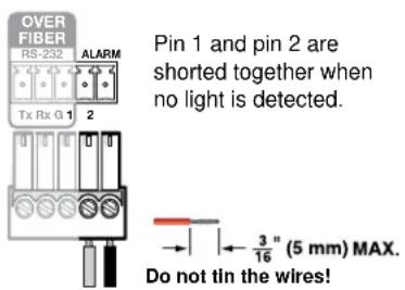
Figure 5. Alarm Connector
NOTE: The length of the exposed (stripped) copper wires is important (see the second and third English language power connector CAUTION bullets on page 6 for details).
Front Panel
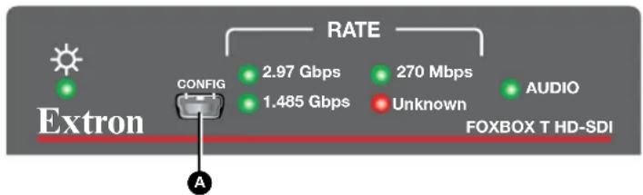
Figure 6. FOXBOX T HD-SDI Transmitter Configuration Connector
Configuration port — Plug a computer or other device into the transmitter via this USB mini-B port for remote control of the transmitter using SIS commands. See Programming Guide, beginning on page 10 for a detailed listing of SIS commands.
Indications and Operation
Indications
All indicators are on the front panel (see figure 7).
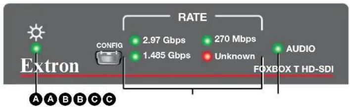
Figure 7. FOXBOX T HD-SDI Transmitter Indicators
A Power indicator — Indicates that the transmitter is receiving power.
B Rate indicators — Indicate the input video rate detected on the 3G/HD/SDI input BNC. The recognized rates are 2.97 Gbps, 1.485 Gbps, and 270 Mbps. The Unknown LED indicates that an input is detected, but that the transmitter does not recognize the rate.
NOTES:
- All four Rate LEDs blink repeatedly if a fiber optic connector module on the rear of the unit is unseated.
- The transmitter equalizes and distributes the input whether it recognizes the rate or not.
C Audio indicator — Indicates that the transmitter is detecting a digital or analog audio input.
Operation
After the transmitter, the connected receiver, and their connected devices are powered up, the system is fully operational. If any problems are encountered, verify that the cables are routed and connected properly, and that the display device has the proper resolution and refresh rate selected. If your problems persist, call the Extron S3 Sales & Technical Support Hotline. See the contact numbers at the end of this guide for the Extron office nearest you.
To take advantage of the various adjustments and test patterns available in the transmitter, you need to connect a computer or other USB device to the front panel Configuration port on either unit and operate using SIS commands (see Programming Guide, beginning on the next page).
Programming Guide
This section describes the remote operation of the FOXBOX T HD-SDI Transmitter via Simple Instruction Set control, including:
- Configuration Port
• Host-to-Transmitter Communications
• Unit-initiated Messages - Error Responses
- Timeout
• Using the Command and Response Table
Configuration Port
A connected computer can communicate with the transmitter via the front panel Configuration port, a USB mini-B port (see item A, on page 8). A standard USB cable can be used for remote control of the transmitter. The USB cable must be terminated on one end with a USB mini-B male connector.
Host-to-Transmitter Communications
SIS commands consist of one or more characters per field. No special characters are required to begin or end a command character sequence. When a command is valid, the switcher executes the command and sends a response to the host device. All responses from the switcher to the host end with a carriage return and a line feed (CR/LF = ←), which signals the end of the response character string. A string is one or more characters.
Unit-initiated Messages
When a local event, such as an equipment power-up, occurs, the unit responds by sending a message to the host. The unit-initiated messages are listed below:
(c) Copyright 20yy, Extron Electronics FOXBOX T HD-SDI, Vx.xx, 60-xxx-xx
The connected unit issues the appropriate copyright message (above) when it first powers on. Vx.xx is the firmware version number; 60-xxx-xx is the part number of the connected unit.
2LnkX10•RteX11•AudI X12•T←
The unit sends the status message whenever there is a change in input video, input audio, or the fiber link. X10, X11, and X12 are defined starting on the next page.
Error Responses
When the transmitter receives a valid SIS command, it executes the command and sends a response to the host device. If the transmitter is unable to execute the command because the command is invalid or it contains invalid parameters, the transmitter returns an error response to the host. The error response codes are:
E10 - Invalid command
E13 — Invalid parameters
E14 — Not valid for this configuration
E17 — Invalid command for signal type
E22 — Busy
Timeout
Pauses of 10 seconds or longer between command ASCII characters result in a timeout. The command operation is aborted with no other indication.
Using the Command and Response Table
The command and response table begins below. Symbols are used throughout the table to represent variables in the command and response fields. Command and response examples are shown throughout the table. The ASCII to HEX conversion table below is for use with the command and response table.
← = Carriage return/line feed
← = Carriage return (no line feed)
| = Pipe (can be used interchangeably with the
← character)
- = space
Esc = Escape key
W = Can be used interchangeably with the Esc character
X1 = On and off, enable and disable status
X2 = Test pattern
X3 = Audio input
X4 = AESC digital channel pair
X5 = AESG digital channel group
X6 = Audio gain adjustment range
X7 = Audio level adjustment range
X8 = Audio attenuation adjustment range
X9 = Plus mode status
X10 = Device name
X11 = Input status
∅ = off or disable 2 = on or enable
∅ = none 1 = color bars
∅ = auto (default) 2 = analog
1 = 2-channel digital
1 (default) or 2
1 (default) or 2
∅∅ to 1∅
-18 to +10 (in 1.0 dB steps)
∅∅ to 18
∅ = disable Plus mode 1 = enable Plus mode (default)
Up to 24 alphanumeric characters, plus minus sign (-). The last character cannot be a minus sign.
∅ = input not detected 1 = input detected
FOXBOX T HD-SDI Fiber Optic Transmitter • Programming Guide 11
X12 = Input video format detected
∅ = no signal
1 = SD 480i
2 = SD 576i
3 = HD-720p (50-60 Hz), 1080i (50-60 Hz), 1080p (23.98-30Hz), 2K (2048x1080p [23.98-30Hz])
4 = 3G-SDI-1080p (@50Hz, 59.94Hz, and 60Hz), 2k (2048x1080p@ 50, 59.94 Hz, and 60Hz)
5 = Unknown
X13 = Audio input selected
∅ = no audio
1 = digital
2 = analog
X14 = Firmware version
v.vv
X15 = Build version v.vv
X16 = Internal temperature
nnnF•nnC
X17 = SFP module manufacturer Alphanumeric character string
X18 = Transmit or receive optical power Optical power in dBm
X19 = Operating temperature
nnc
Command and Response Table for SIS Commands
| Command Function | SIS Command (Host to Unit) | Response (Unit to Host) | Additional description | ||||||
| Loop-through video mute | |||||||||
| NOTE: These commands affect the output on the Loop-through port (see item B on page 4) only. The video transmitted to the connected receiver is unaffected. | |||||||||
| Mute output | 2B | Vmt2← | Blank the Loop-through port video output. | ||||||
| Unmute output | ∅B | Vmt∅← | Output video on the Loop-through port. | ||||||
| Show video mute status | B | X1← | Video mute status is X1. | ||||||
| Test pattern | |||||||||
| Output color bars | Esc1TEST← | Test1← | Output the color bars test pattern. | ||||||
| Turn test pattern off | Esc0TEST← | Test0← | Output the input video (no test pattern is selected). | ||||||
| Show test pattern status | EscTEST← | X2← | |||||||
| Audio input selection | |||||||||
| Select audio input | EscI X3AFMT← | Afmt IX3← | Select the X3 audio to output on the fiber cable. In Auto, digital takes priority over analog. | ||||||
| Show audio input | EscIAFMT← | X3← | |||||||
| AES digital audio channel selection | |||||||||
| NOTE: Eight-channel audio is divided into two groups, each consisting of two channel pairs (four channels). The table at right shows the channels contained within each group. | Group 1 | Group 2 | |||||||
| Ch Pair 1 | Ch Pair 2 | Ch Pair 1 | Ch Pair 2 | ||||||
| Ch 1 | Ch 2 | Ch 1 | Ch 2 | Ch 1 | Ch 2 | Ch 1 | Ch 2 | ||
| Select channel | EscX4 AESC← | AescX4← | Select digital audio channel pair on which audio will be embedded. | ||||||
| Show channel | Esc AESC← | X4← | |||||||
| AES digital audio group selection | |||||||||
| Select group | EscX5 AESG← | AesgX5← | Select digital audio channel group on which audio will be embedded. | ||||||
| Show group | Esc AESG← | X5← | |||||||
| NOTE: X1 = Video mute status ∅ = off (default) 2 = onX2 = Test pattern ∅ = none 1 = color bars onX3 = Audio input ∅ = auto (default) 2 = analog1 = 2-channel digitalX4 = AESC digital channel pair 1 (default) or 2X5 = AESG digital channel group 1 (default) or 2 | |||||||||
| Analog audio input gain and attenuation | |||||||||
| NOTE: The set gain (G) and set attenuation (g) commands are case sensitive. The increment level, decrement level, and show level are not case sensitive. | |||||||||
| Set input audio gain to a +dB value | x6G Aud | x7← | Set the input level (gain) to +x8 dB. | ||||||
| Example: | 2G | Aud+02← | Set the input level (gain) to +2 dB. | ||||||
| Set input audio attenuation to a -dB value | x8g Aud | x7← | Set the input level (attenuation) to -x6 dB. | ||||||
| Increment input level | +G | Audx7← | Increase the audio level by 1 dB. | ||||||
| Example: | +G Aud+03 | ← | Increase the input level from +2 dB to +3 dB. | ||||||
| Decrement input level | -G Aud-01 | ← | Decrease the audio level from 0 dB to -1 dB. | ||||||
| Show input level | G | x7← | |||||||
| Plus mode transmission | |||||||||
| Enable Plus mode transmission | 81*1# Plus1 | ← | Enable if the inserter is connected to a Plus mode device. | ||||||
| Disable Plus mode transmission | 81*0# Plus | 0← | Disable if the inserter is connected to a non-Plus-mode device. | ||||||
| View Plus mode | 81# | x9← | |||||||
| Device name | |||||||||
| Write device name | Escx10CN← | Ipn•x10← | Assign a custom name to the transmitter. | ||||||
| Reset device name | Esc•CN← | Ipn•FOXBOX•T•HD-SDI← | Reset the name to the factory default. | ||||||
| Show device name | EscCN← | x10← | Audio mute status is x1. | ||||||
| NOTE: x9 = Plus mode status 0 = disable Plus mode 1 = enable Plus mode (default)x6 = Audio gain adjustment range 00 to 10x7 = Audio level adjustment range -18 to +10 (in 1.0 dB steps)x8 = Audio attenuation adjustment range 00 to 18x10 = Device name Up to 24 alphanumeric characters, plus minus sign (-).The first character must be alphanumeric; the last character cannot be a minus sign.Information requests | |||||||||
| Information request | I2Lnk | X11•Rte X12•Aud I X13•T← | The unit responds with the current status (signal detected) of optical link 2, the detected video input, the selected audio input, the device type (T for transmitter). | ||||||
| Show firmware version | Q | X14← | |||||||
| Example: | Q | 1.23← | The factory-installed firmware version is 1.23 (sample value only). | ||||||
| Show firmware version and build | *Q | X14, X15← | |||||||
| Show downloaded firmware version | 35Q | X14← | |||||||
| Request part number | N60- | nnn-nn← | See www.extron.com. | ||||||
| Show link 2 status | 2S | X11← | Light status on receiver-Tx-to-transmitter-Rx cable. | ||||||
| Show input video status | 4S | X11← | Show transmitter video input status. | ||||||
| Show input audio status | 5S | X13← | Show transmitter audio input status. | ||||||
| Show temperature | 20S | X16← | Show temperature in degrees Fahrenheit and Celsius. | ||||||
| Show SFP module | 40S | X17•X18Tx•X18Tx•X19← | Show SFP module manufacturer, transmitting power in dBm, receiving power in dBm, and SFP module temperature in degrees Celsius. | ||||||
| Resets | |||||||||
| Reset audio | EscZA← | Zpa← | Reset audio setting to default levels (0 dB gain). | ||||||
| System reset | EscZXXX← | Zpx← | Reset all settings to factory defaults. | ||||||
| NOTE: X11 = Input status θ = input not detected 1 = input detected | |||
| X12 = Input video format detected θ = no signal | |||
| 1 = SD 480i | |||
| 2 = SD 576i | |||
| 3 = HD-720p (50-60 Hz), 1080i (50-60 Hz), 1080p (23.98-30Hz),2K (2048x1080p [23.98-30Hz]) | |||
| 4 = 3G-SDI-1080p (@50Hz, 59.94Hz, and 60Hz), 2k (2048x1080p@ 50, 59.94 Hz, and 60Hz) | |||
| 5 = Unknown | |||
| X13 = Audio input selected | θ = no audio | 1 = digital | 2 = analog |
| X14 = Firmware version v.vv | |||
| X16 = Internal temperature | nnnF•nnC | ||
| X17 = SFP module manufacturer | Alphanumeric character string | ||
| X18 = Transmit or receive optical power | Optical power in dBm | ||
| X19 = Operating temperature | nnC | ||
Equipment Mounting
This section provides procedures for mounting the FOXBOX T HD-SDI transmitter.
Mounting the Transmitter
ATTENTION:
The 1-inch high, quarter rack width transmitter can be placed on a table, mounted in a rack, or mounted under a desk or table.
Tabletop Use
Affix the included rubber feet to the bottom of the unit and place it in any convenient location.
Mounting kits
Mount the unit using any optional compatible mounting kit listed on the Extron website (www.extron.com), in accordance with the directions included with the kit. For rack mounting, see "UL Rack-Mounting Guidelines," below.
UL Rack-Mounting Guidelines
The following Underwriters Laboratories (UL) requirements pertain to the installation of the unit into a rack.
- Elevated operating ambient temperature — If installed in a closed or multi-unit rack assembly, the operating ambient temperature of the rack environment may be greater than room ambient. Therefore, consider installing the equipment in an environment compatible with the maximum ambient temperature (TMA = +122 °F, +50 °C) specified by Extron.
- Reduced air flow — Installation of the equipment in a rack should be such that the amount of air flow required for safe operation of the equipment is not compromised.
- Mechanical loading — Mounting of the equipment in the rack should be such that a hazardous condition is not achieved due to uneven mechanical loading.
- Circuit overloading — Consideration should be given to the connection of the equipment to the supply circuit and the effect that overloading of the circuits might have on overcurrent protection and supply wiring. Appropriate consideration of equipment nameplate ratings should be used when addressing this concern.
- Reliable earthing (grounding) — Reliable earthing of rack-mounted equipment should be maintained. Particular attention should be given to supply connections other than direct connections to the branch circuit (such as use of power strips).
Extron Warranty
Extron Electronics warrants this product against defects in materials and workmanship for a period of three years from the date of purchase. In the event of malfunction during the warranty period attributable directly to faulty workmanship and/or materials, Extron Electronics will, at its option, repair or replace said products or components, to whatever extent it shall deem necessary to restore said product to proper operating condition, provided that it is returned within the warranty period, with proof of purchase and description of malfunction to:
USA, Canada, South America, and Central America:
Extron Electronics
1230 South Lewis Street
Anaheim, CA 92805
U.S.A.
Japan:
Extron Electronics, Japan
Kyodo Building, 16 Ichibancho
Chiyoda-ku, Tokyo 102-0082
Japan
Europe and Africa:
Extron Europe
Hanzeboulevard 10
3825 PH Amersfoort
The Netherlands
China:
Extron China
686 Ronghua Road
Songjiang District
Shanghai 201611
China
Asia:
Extron Asia Pte Ltd
135 Joo Seng Road, #04-01
PM Industrial Bldg.
Singapore 368363
Singapore
Middle East:
Extron Middle East
Dubai Airport Free Zone
F12, PO Box 293666
United Arab Emirates, Dubai
This Limited Warranty does not apply if the fault has been caused by misuse, improper handling care, electrical or mechanical abuse, abnormal operating conditions, or if modifications were made to the product that were not authorized by Extron.
NOTE: If a product is defective, please call Extron and ask for an Application Engineer to receive an RA (Return Authorization) number. This will begin the repair process.
USA: 714.491.1500 or 800.633.9876
Europe: 31.33.453.4040
Asia: 65.6383.4400
Japan: 81.3.3511.7655
Units must be returned insured, with shipping charges prepaid. If not insured, you assume the risk of loss or damage during shipment. Returned units must include the serial number and a description of the problem, as well as the name of the person to contact in case there are any questions.
Extron Electronics makes no further warranties either expressed or implied with respect to the product and its quality, performance, merchantability, or fitness for any particular use. In no event will Extron Electronics be liable for direct, indirect, or consequential damages resulting from any defect in this product even if Extron Electronics has been advised of such damage.
Please note that laws vary from state to state and country to country, and that some provisions of this warranty may not apply to you.
| Extron Headquarters+1.800.633.9876 (Inside USA/Canada Only)Extron USA - West Extron USA - East+1.714.491.1500 +1.919.850.1000+1.714.491.1517 FAX +1.919.850.1001 FAX | Extron Europe+800.3987.6673(Inside Europe Only)+31.33.453.4040+31.33.453.4050 FAX | Extron Asia+65.6383.4400+65.6383.4664 FAX | Extron Japan+81.3.3511.7655+81.3.3511.7656 FAX | Extron China+86.21.3760.1568+86.21.3760.1566 FAX | Extron Middle East+971.4.299.1800+971.4.299.1880 FAX | Extron Korea+82.2.3444.1571+82.2.3444.1575 FAX | Extron India1800.3070.3777(Inside India Only)+91.80.3055.3777+91.80.3055.3737 FAX |


- Fiber Optic Extenders
- FOXBOX T HD-SDI
- Safety Instructions
- Safety Instructions • English
- Chinese Traditional (繁體中文)
- Copyright
- Trademarks
- Class 1 Laser Product
- Conventions Used in this Guide
- Notifications
- Software Commands
- Specifications Availability
- Contents
- Introduction ...... 1
- Installation and Operation 4
- Programming Guide....10
- Equipment Mounting 15
- Introduction
- About the FOXBOX T HD-SDI Transmitter
- System Compatibility
- Features
- Audio gain and attenuation adjustment capability
- Real-time status LED indicators for troubleshooting and monitoring
- Compatible with the following Extron FOX Series products:
- Installation and Operation
- Connections and Features
- ATTENTION:
- Connector and cable details
- Power supply wiring
- CAUTION:
- ATTENTION :
- RS-232 connector wiring
- NOTES:
- Indications and Operation
- Indications
- Operation
- Programming Guide
- Configuration Port
- Host-to-Transmitter Communications
- Unit-initiated Messages
- Error Responses
- Timeout
- Using the Command and Response Table
- Command and Response Table for SIS Commands
- Equipment Mounting
- Mounting the Transmitter
- Tabletop Use
- Mounting kits
- UL Rack-Mounting Guidelines
- Extron Warranty
- USA, Canada, South America, and Central America:
- Japan:
- Europe and Africa:
- China:
- Asia:
- Middle East:
Brand : Extron
Model : FOXBOX T HD-SDI
Category : Electronics