
SDD2ELEMTC88 - Range hood SIRIUS - Free user manual and instructions
Find the device manual for free SDD2ELEMTC88 SIRIUS in PDF.


| Product Type | Range Hood |
| Brand | Sirius |
| Model | SDD2ELEMTC88 |
| Dimensions (cm) | 60 (W) x 50 (D) x 12 (H) |
| Weight (kg) | 12 |
| Power Supply | 220-240V, 50Hz |
| Motor Power (W) | 180 |
| Max Airflow (m³/h) | 500 |
| Noise Level (dB) | 55 |
| Control Type | Push Buttons |
| Lighting | 2 x 2W LED |
| Filter Type | Aluminum Grease Filter |
| Number of Speeds | 3 |
| Installation Type | Ducted / Recirculating |
| Material | Stainless Steel |
| Energy Class | B |
| Included Accessories | Carbon Filter, Installation Kit |
| Warranty | 2 Years |
| Recommended Cleaning | Wipe with damp cloth, wash grease filter monthly |
| Spare Parts Availability | Filters, bulbs, control board available |
Frequently Asked Questions - SDD2ELEMTC88 SIRIUS
User questions about SDD2ELEMTC88 SIRIUS
0 question about this device. Answer the ones you know or ask your own.
Ask a new question about this device
Download the instructions for your Range hood in PDF format for free! Find your manual SDD2ELEMTC88 - SIRIUS and take your electronic device back in hand. On this page are published all the documents necessary for the use of your device. SDD2ELEMTC88 by SIRIUS.
USER MANUAL SDD2ELEMTC88 SIRIUS
Congratulations on your purchase!
Thank you for choosing a Sirius product.
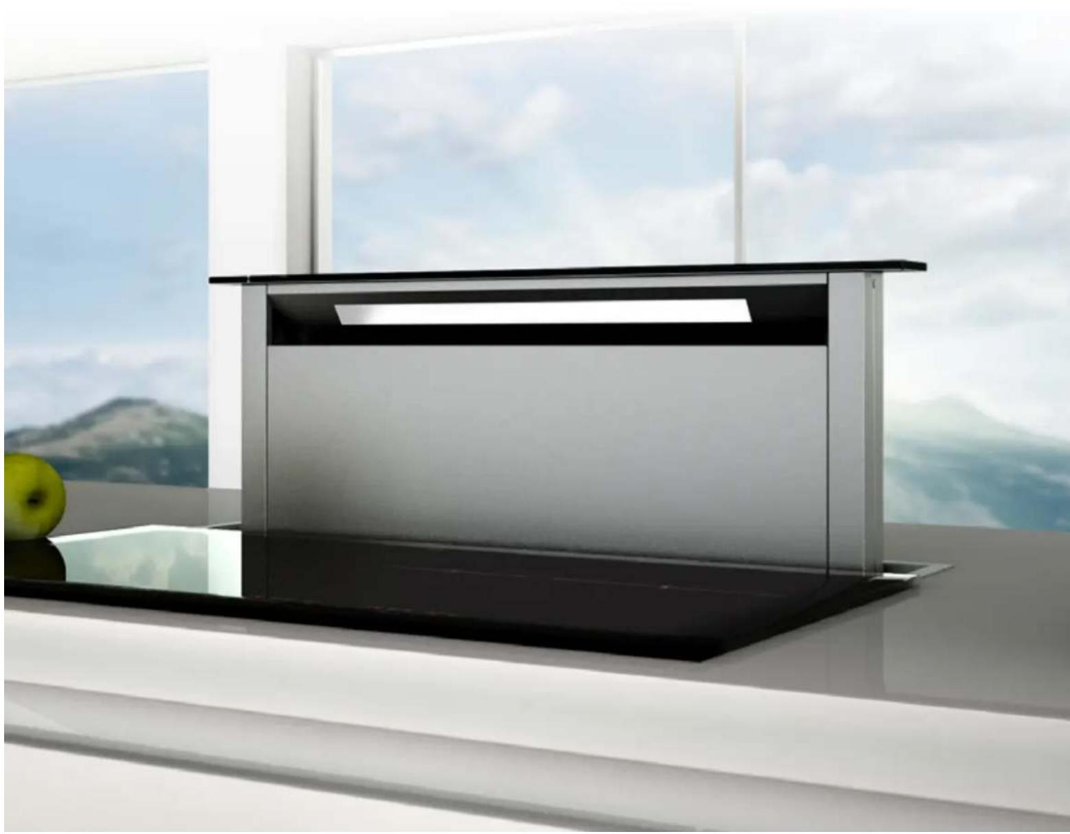
SDD2ELEMTC FLUSH TOP
DOWNDRAFT INSTALLATION INSTRUCTIONS FOR
SEM 11, SEM 21, SEM 71, SEM 81 & DDFMEL motors
SDD2ELEMTC58
SDD2ELEMTC88
SDD2ELEMTC118
EAN #9351116005344
EAN #9351116005351
EAN #9351116005368
natural_image
Modern minimalist kitchen appliance with black and silver panels, displayed on a glass table near a window overlooking a distant landscape (no text or symbols visible)TO THE ATTENTION OF THE USER 3
INSTALLATION GUIDELINES 3
APPLIANCE DIAGRAMS 4
PRE-INSTALLATION CHECKS 4
INSTALLING THE RANGEHOOD 5
INSTALLATION INSTRUCTIONS
FOR SEM 11 AND SEM 21
150MM SIDE OR BOTTOM VENTING 7
FOR SEM 71 AND SEM 81
200MM SIDE OR BOTTOM VENTING 8
FOR SEM 11, SEM 21, SEM 71, AND SEM 81
150MM / 200MM FRONT OR REAR VENTING 10
FOR DDFMEL
150MM BOTTOM VENTING 11
DUCTING FROM MOTOR TO VENT (SEM 11 & 81 ONLY) 12
ELECTRICAL CONNECTION 12
HOW THE RANGEHOOD WORKS 14
CLEANING THE RANGEHOOD 15
TROUBLESHOOTING 15
REPLACING THE LIGHT 16
PARTS LIST 17
WIRING DIAGRAM 20
natural_image
Symbol of a trash bin crossed with a horizontal line and a rectangular block below (no text or numbers present)The symbol on the product or on its packaging indicates that this product may not be treated as house-hold waste. Instead it shall be handed over to the applicable collection point for the recycling of electrical and electronic equipment. By ensuring this product is disposed of correctly, you will help prevent potential negative consequences for the environment and human health, which could otherwise be caused by inappropriate waste handling of this product. For more detailed information about recycling of this product, please contact your local city office, your household waste disposal service or the shop where you purchased the product. This appliance is marked according to the European directive 2002/96/EC on waste electrical and electronic equipment (WEEE).
TO THE ATTENTION OF THE USER
This rangehood is designed to work with ducted outside evacuation.

WARNING

Keep these instructions for use with the appliance. If the appliance should be sold or passed on to others, make sure that the instructions are passed on with it. We thank you for taking note of these suggestions before installing and using the appliance. They have been written for your personal safety and the safety of others.
SAFETY INSTRUCTIONS
These hoods have been designed for personal use in the home. The appliance must be used by adults. Make sure that the appliance is out of reach of children and that they do not use it to play with. Make sure that children do not operate the controls.
- When the appliance is delivered, check the overall appearance of the packaging. Check PARTS LIST on page 17 for all included parts prior to discarding packaging.
Any remarks should be written on the delivery coupon, of which you keep a copy.
Your appliance is designed for normal domestic use. It is not designed for commercial or industrial use, or for purposes other than those for which it was designed.
- Any consequences of or damage from incorrect installation or incorrect use of the appliance will not be covered by the manufacturer's guarantee.
- Do not ever change or try to change the characteristics of this appliance. This would be a danger. Repairs must be performed only by an authorised technician.
- Always disconnect the hood before carrying out cleaning or maintenance operations.
- Adequately ventilate the room when a rangehood and other appliances, powered by energy other than electricity, are used simultaneously, so that the hood does not suck any combustion fumes.
- It is not allowed to cook food over open flames (flambé) or operate gas hobs without pots or pans on them under the hood itself (the flames sucked into the hood might damage the appliance).
- Frying under the appliance must be done under constant supervision as hot oils and fats may ignite.
- Respect the guidelines for cleaning and replacement of grease filters. Accumulated deposits of grease are a fire hazard.
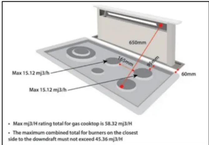
INSTALLATION GUIDELINES FOR GAS COOKTOP APPLICATIONS
- A minimum 60mm gap must be left between the stainless steel frame and the nearest edge of the cooktop.
- The minimum distance between the border of the gas cooktop and the nearest burner must not be less than 95mm
- For the downdraft to operate at a premium, the distance between the downdraft opening and the furthest burner shall not exceed 650mm.
- Distance between the burners on the side closest to the downdraft shall not be closer than 165mm.
- This appliance must not be used over cook tops powered by wood or coal or in any case, over cook tops with power levels that could damage the appliance.
- Never use steam or high-pressure devices for cleaning your hood (regulations regarding electrical safety).
- Never use the rangehood without the grease filters.
- The minimum distance between the Downdraft (closed) and the surface above it must be at least 800 mm.
- When handling the downdraft, never put your hands in the field of action of the extractable unit.
At Sirius, we are constantly seeking to improve our products. We reserve the right to modify their technical, functional, or aesthetic characteristics deriving from their upgrading.
Motors manufactured and approved by Sirius only are to be used at all times. Failure to comply with this will result in the forfeit of the manufacturer warranty.
The air collected must not be conveyed into a flue used for smoke or fumes from appliances powered by anything other than electricity (central heating systems, bathroom and toilet exhausts, etc.). As far as discharging exhaust air is concerned, please follow the guidelines given by competent authorities.
APPLIANCE DIAGRAMS
DUCTING TYPES
- Side / bottom venting - SEM 11, SEM 21 motor pg.7
- Side / bottom venting - SEM 71, SEM 81 motor pg.8
- Front / rear venting - SEM 11, SEM 21, SEM 71, SEM 81 motor pg.10
- Front / rear venting - DDFMEL motor pg. ??
BEFORE YOU INSTALL
Sirius warranty covers only Sirius product. If you choose to install a non-Sirius branded accessory such as flexible ducting, Sirius will only warrant the hood and motor. If installation is found to be the cause of failure or issue then charges will apply for service and parts.
Flexible ducting is not permitted under any circumstances. Flexible ducting has been found to increase noise levels, increase vibration and reduce airflow. Sirius Semi-rigid or solid ducting can be used in lieu. There is a range available to suit any application.
Available at www.siriusbrand.com
A reduction in the duct diameter from stated ducting size will void warranty. If you are in doubt about the ducting, please contact Sirius on 1300 762 219 prior to installation.
INSTALLING THE RANGEHOOD
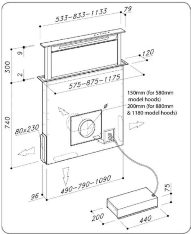
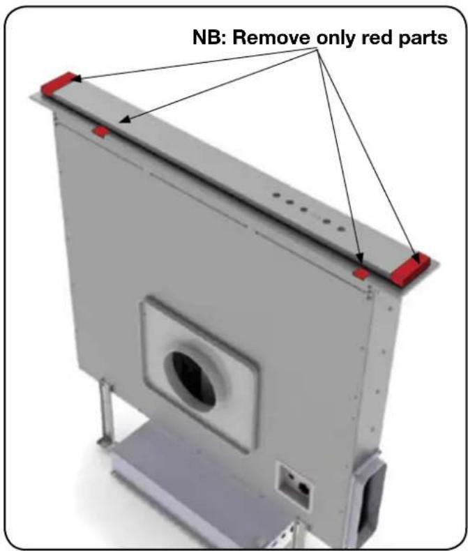
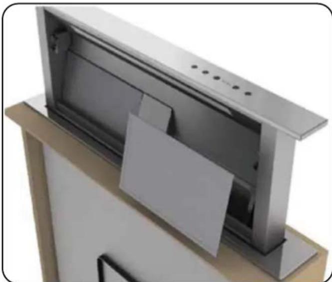
- Before carrying out the appliance installation, please check that all components are not damaged, in such a case contact your retailer and do not carry out any installation operation. Before the installation of the downdraft, please remove the safety piece you can see in the picture (Fig. 1). Leave all other protective tape in place at this point. Furthermore, please read carefully all of the following installation instructions.
- Use Sirius ducting with a maximum length of 7 metres to the motor.
- Limit the number of elbows in the ducting, since each elbow reduces the air capacity of 1 linear meter. (Ex: if you use no. 2 × 90^ elbows, the length of piping should not exceed 5 meters).
- Avoid abrupt direction changes. (Optimum angle 45^ when required)
- Use a 150 mm for 580mm models, - 200mm ducting for larger models - constant diameter pipe for the whole length.
Use ducting approved by standards enforced - see www.siriusbrand.com.au for approved ducting The manufacturer shall not be deemed responsible for air capacity or noise problems caused by failure to comply with the above instructions and no warranty on the product shall be provided.
STEP 1:
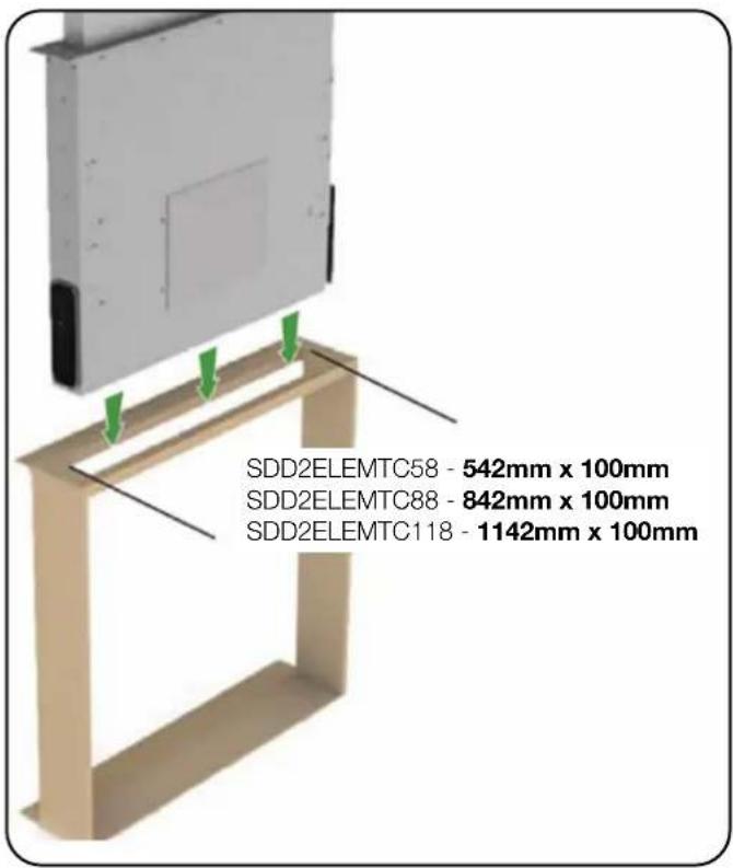
Refer to cutout dimensions required per unit as they vary for each unit.
- Before making the cutout, check that there are no structural or other parts inside the cabinet where the appliance is to be placed which could hinder a proper installation. Check that the dimensions of the downdraft and the cooktop are compatible with the cabinet so that the installation can be carried out properly.
-
Make a rectangular cutout in the back of the cooktop:
-
542mm x 100mm for the 580mm model
- 842mm x 100mm for the 880mm model
- 1142mm x 100mm for the 1180mm model.
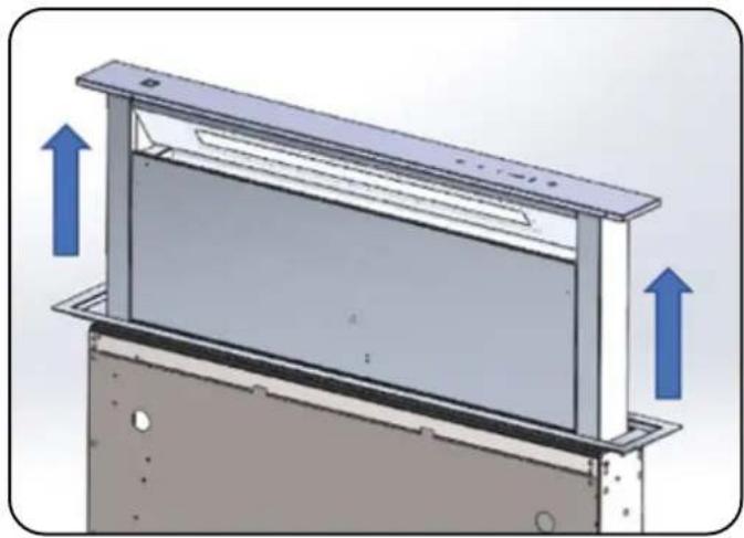
- Put the downdraft in the opening, inserting it from above as shown in (Fig. 2)

WARNING

Technical specifications and product sizes can be varied by the manufacturer without notice. Cut out dimensions are indicative only and physical measurement should be taken as a precautionary measure to ensure no issues arise with fitment.
(Fig. 1) (Fig. 2)
INSTALLATION INSTRUCTIONS
SIDE OR BOTTOM VENTING
(For front or rear venting instructions, see pages 10-12)
STEP 2:
- Remove front 150mm or 200mm adaptor plate (Part 'D') (Fig. 3)
- Replace Part 'D' with front cover plate (Part 'E')
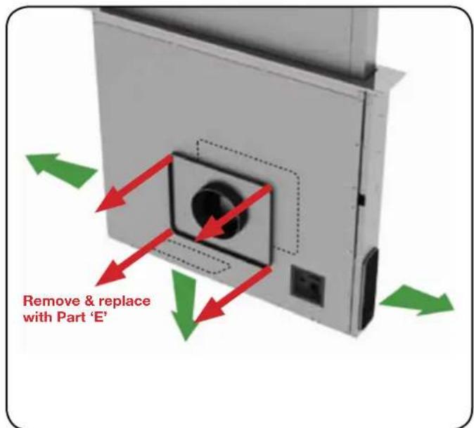
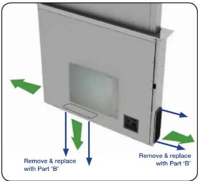
(Fig. 3) (Fig. 4)
STEP 3:
- Remove side or bottom cover plate (Part C). (Fig. 4)
- Connect air outlet collar (Part 'B') to the same fixing points as removed from side or bottom cover plate (Part 'C') and tighten.
STEP 4:
- Carefully lower downdraft into cutout cabinetry.
- Fix the downdraft inside the cabinet, using the special fixing brackets (Part 'F') supplied with the product.
- Insert the brackets in the lower side of the downdraft in such a way that there is a 2 mm distance between the lower side of bracket and the bottom of the cabinet.
- This distance will allow the traction to be positioned downwards of the product, at the moment of fixing, in order to have the stainless steel trim perfectly adhering with the work surface.
- Before inserting the screws, please make sure that the appliance is perfectly perpendicular with the work surface, ensuring unit is square and levelled with spirit level before turning on. (Fig. 5)
NB: If the unit is not levelled, the downdraft will shudder when rising. This could cause damage to your unit, which is not covered by warranty. This is installation damage.
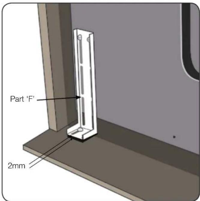
(Fig. 5)
STEP 5:
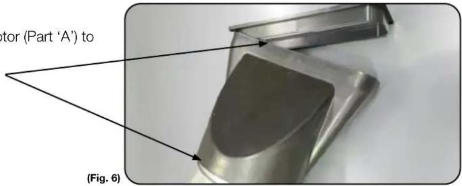
- Connect rectangular to round adaptor (Part 'A') to air outlet (Part 'B'), (Fig. 6).
- Secure both ends with duct tape
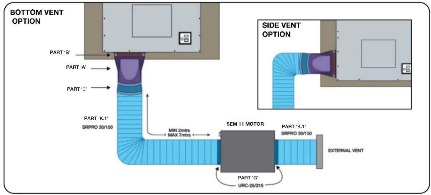
STEP 6A: Ducting to SEM 11 motor (150mm ducting)
This step covers ducting for SDD2ELEMTC58 models only. For 880mm & 1180mm models, see Step 6B.
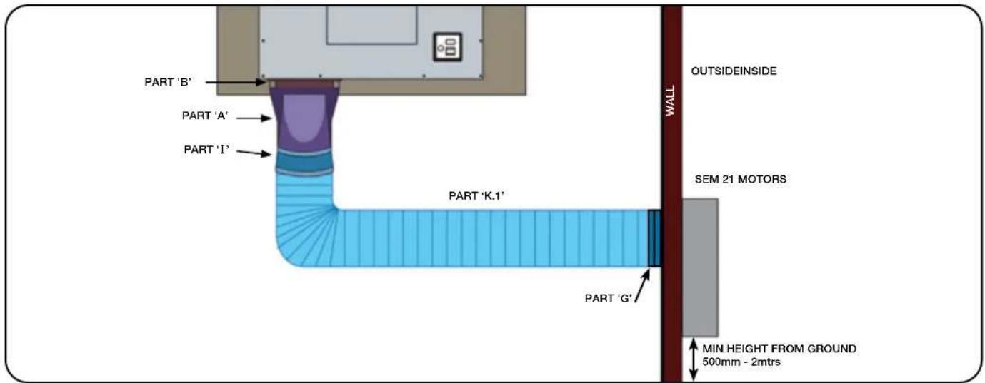
1A: Connect the top of the 150mm connector piece (Part 'I') to the round outlet on adaptor (Part 'A'), then connect length of 150mm ducting (Part 'K.1') to the bottom of the 150mm connector piece (Part 'I').
2A. Secure to the motor with a universal ring clamp (Part 'G').
• See page 12 for ducting from motor to vent (N/A for SEM 21 motors)
STEP 6A: Ducting to SEM 21 motor (150mm ducting)
STEP 6B: Ducting to SEM 71 motor (200mm ducting)
This step covers ducting for SDD2ELEMTC88/118 models. For the 580mm model, see Step 6A.
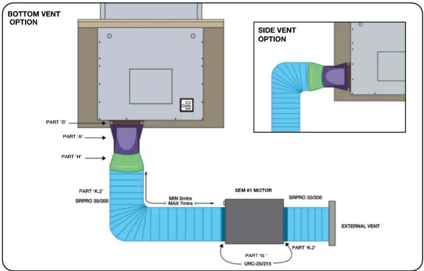
For SEM 81 motor with SDD2ELEMTC88/118 - 200mm option only.
1B: Connect a duct expander (Part 'H') to rectangular to round adapter (Part 'A'), then connect length of ducting (Part 'K.2') to the 200mm outlet.
2B: Secure to the motor with a universal ring clamp (Part 'G').
• See page 12 for ducting to vent (N/A for SEM 71 motor)
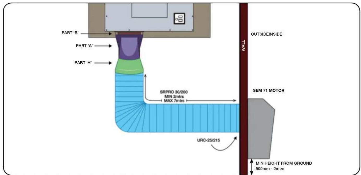
STEP 6B: Ducting to SEM 81 motor (200mm ducting)
INSTALLATION INSTRUCTIONS FOR SEM 11, SEM 21, SEM 71, SEM 81
FRONT OR REAR VENTING
(For side or bottom venting instructions, see pages 7 - 9)
STEP 2:
If venting from front, check to see if front adaptor plate (Part 'D') is attached.
- If venting from the rear, remove 150mm or 200mm adaptor plate (Part 'D') and replace with front cover plate (Part 'E').
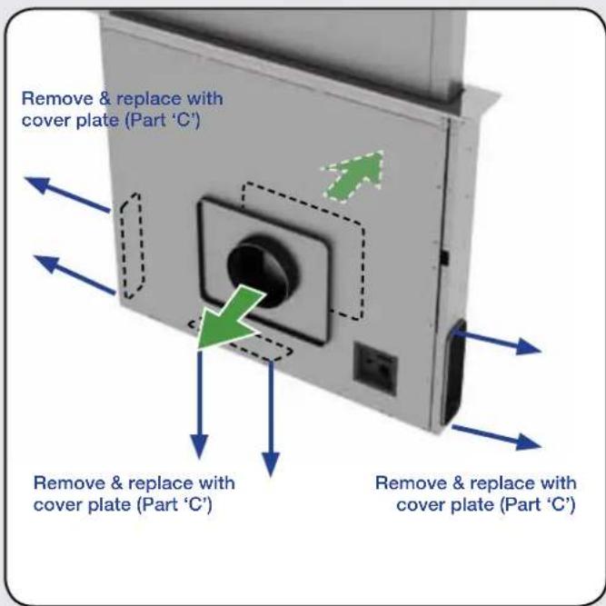
(Fig. 7)
STEP 3:
- Carefully lower downdraft into cutout cabinetry.
- Fix the downdraft inside the cabinet, using the special fixing brackets (Part 'F') supplied with the product.
- Insert the brackets in the lower side of the downdraft in such a way that there is a 2 mm distance between the lower side of bracket and the bottom of the cabinet.
- This distance will allow the traction to be positioned downwards of the product, at the moment of fixing, in order to have the stainless steel trim perfectly adhering with the work surface.
- Before inserting the screws, please make sure that the appliance is perfectly perpendicular with the work surface, ensuring unit is square and levelled with spirit level before turning on. (Fig. 5)
NB: If the unit is not levelled, the downdraft will shudder when rising. This could cause damage to your unit, which is not covered by warranty. This is installation damage.
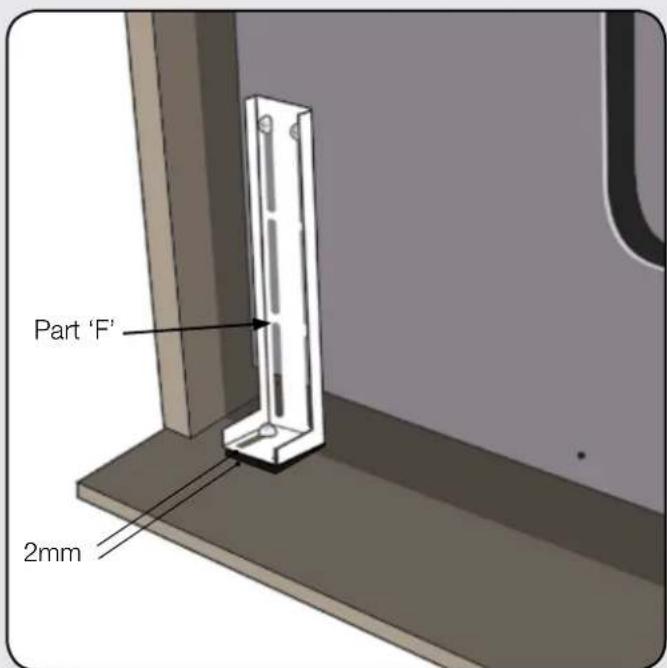
(Fig. 5)
STEP 4:
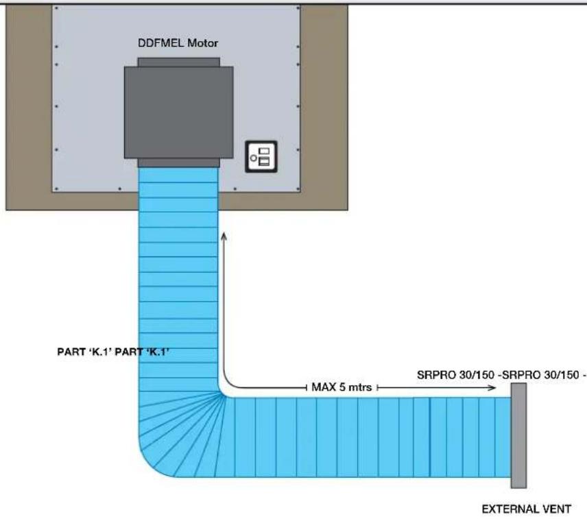
- Use 150mm ducting (Part 'K.1') for SDD2ELEMTC58 versions or 200mm ducting (Part 'K.2') for SDD2ELEMTC88/118 versions.
- The ducting fits directly onto the collar on the front adaptor plate (Part 'D').
- Fix in place using a universal ring clamp (Part 'G').
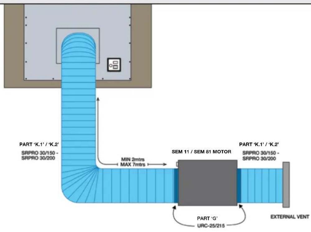
Ducting to SEM 11 / SEM 81 motor (internal motor)
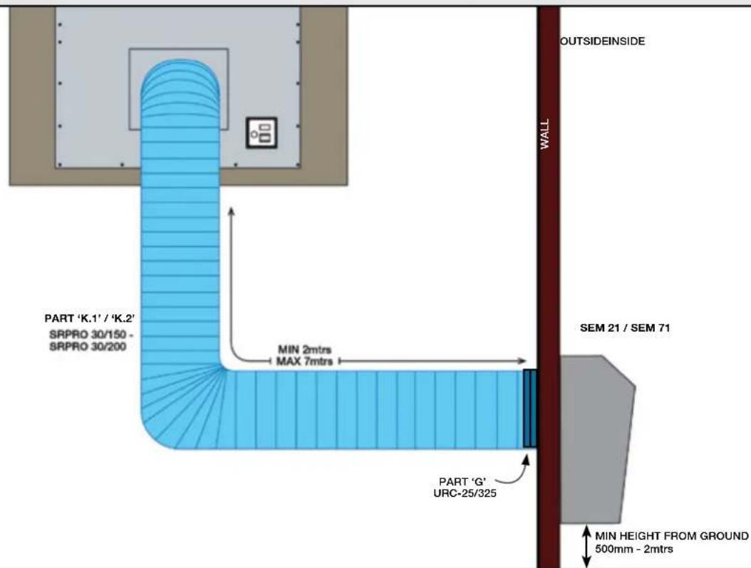
Ducting to SEM 21 / SEM 71 motor (external motor)
Ducting to DDFMEL motor (internal motor)
DUCTING FROM MOTOR TO WALL VENT: (SEM 11 and SEM 81)
- Run the length of ducting to the motor. (Additional lengths of ducting can be attached using an additional internal connector pieces.)
NOTE: No connector required as it connects directly to the collar of the motor.
- Secure with another universal ring clamp (Part 'G').
NOTE: The location of the motor is to be no less than 2 metres away from the downdraft. Failure to do so may result in additional noise level of the downdraft. Maximum distance is 7 metres, however 3 - 5 metres is optimum to minimise noise and maximise performance.
- Using another length of semi-rigid duct run from the exit collar on the SEM 11 / SEM 81 to a predetermined exit point and connect to weatherproof vent with a clamp.
See www.siriusbrand.com for multiple vent options or see our nearest retail partner.
ELECTRICAL CONNECTION
Power transformer can be located anywhere beneath the bench. It must be accessible for servicing.

NOTE

We recommend installing the power transformer at least 10 cm above floor level and at a suitable distance from all heat sources (e.g. oven sides or cook top).

WARNING

Place the power transformer at a distance of no less than 65 cm from gas cooktops.
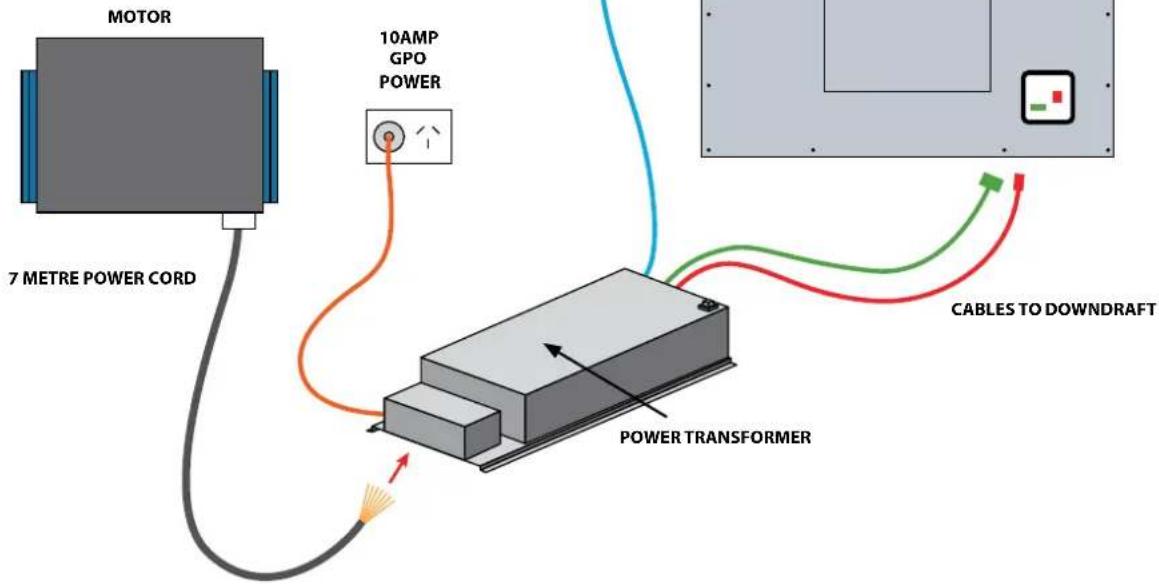
ELECTRICAL CONNECTION

NOTE

This appliance complies with the European Directives 2006/95/EC (Low Voltage Directive) and 2004/108/EC (Electromagnetic Compatibility).
While installing the appliance and carrying maintenance operation, make sure it is disconnected from the electrical network or the fuses are cut out or removed.
Check that:
• Power is connected.
- Feeder lines (mains) are in good conditions.
- The cables diameter complies with installation regulations.

WARNING

The downdraft connection to the electrical network must be carried out only by professional and qualified technicians.
The downdraft must be connected to a properly installed and suitable electrical network. The electrical system must comply with VDE0100 standard.

DANGER

If the rangehood presents any anomaly, disconnect the appliance or remove the fuse corresponding to the appliance power disconnecting line.
If the appliance has no plug or if the plug is not easily accessible, then a device needs to be fitted to disconnect off from the electric network; this device must have an opening distance between contacts on all poles of at least 3 mm.

CAUTION

This appliance is fitted with an H05 VVF 3 conductor, 0.75 mm2 (neutral, phase, and ground) power cord. This can be connected up to a 220 - 240 V monophase electrical network through a CEI 60083 approved power socket (10AMP power socket), which must remain accessible after installation, in compliance with installation regulations. We decline any responsibility in case of accidents caused by a lack of ground connection or incorrect ground connection. The appliance must be fed through a differential protection device (RCD), with a nominal residual current not exceeding 30mA. If the power cord is damaged, call the after-sales service to avoid any risk.

WARNING

After having replaced the filters, reinstall the front stainless steel panel, otherwise the Downdraft is not enabled to function.
natural_image
Exterior view of a modern stainless steel filing cabinet with open doors and ventilation slots (no text or symbols visible)(Fig. 8)

NOTE

Water splashing against the enclosure from any direction shall have no harmful effect, utilizing either: a) an oscillating fixture, or b) A spray nozzle with no shield.
Test a) is conducted for 10 minutes. Test b) is conducted (without shield) for 5 minutes minimum.
Oscillating tube: Test duration: 10 minutes, or spray nozzle (same as IPX3 spray nozzle with shield removed).
HOW THE RANGEHOOD WORKS

Light On/Off Decrease fan


speed

Fan speed indicators

Increase fan speed

10 min shut-off
timer
A: Light ON/OFF key
The light switches on and off only when the carriage is fully OPEN.
Pressing this button with the carriage closed will cause the carriage to open and then the light will switch on.
The button also serves to switch off the light if it is on.
B: ↑↓ ON/OFF key
This starts the extraction carriage upward movement and when it is fully open, it sets the second extraction speed.
With the carriage open: it switches off the motor and if on, the light; then it retracts the extraction carriage.
C: — Decrease fan speed key
This reduces the speed of the extractor motor from the 4th speed until the motor switches off, without closing the pullout carriage.
D: Fan speed Indicators
- This signals the speed setting, by only the relevant LED switching on.
- Lights flashing signals reminder to wash mesh grease filters. (see grease filter saturation)
E: + Increase fan speed key
This increases the speed of the extractor motor, from 1st to 4th speed, without moving the extractor panel.
F: 10 Minute shut-off timer
10 min after setting, it serves to stop the extractor motor, close the carriage and switch the lights off, if they are on. The set function is signalled by the flashing LEDs "D" for the set speed. The timer can be cancelled by pressing the key again.
Automatic turn off:
After 4 hours of continuous working from the last setup, the appliance turns off and closes automatically. This ensures the unit cannot accidentally be left running whilst away.
Grease filters saturation:
After 30 hours of working, the speed indicators “D” will all flash simultaneously, signaling the grease filters saturation.
To reset this alarm, hold down the "TIMER" button for at least 3 seconds, while the carriage is open.
Calibration:
The rangehood carries out its self-calibration every 3 complete cycles of its extractable unit.
By pushing the "TIMER" key 6 times consecutively (MAX break between one push and the other is 3 sec.) all the LEDs will flash and the calibration will be reset.
After the next 3 cycles the downdraft will carry out its self-calibration.
Stand-by:
When the extractable unit is closed and the light is switched off, the control panel, after 6 seconds, activates the Stand-by function, reducing the brightness of the leds.
This function can be stopped by pressing ON/OFF or LIGHT key.
Safety close function:
If an obstacle is preventing the downdraft from lowering completely, the downdraft will automatically raise to prevent damage to the unit.

WARNING

This operation has to be carried out by a specialised technician.
CLEANING THE RANGEHOOD
Careful maintenance ensures proper operation and good performances over time.

CAUTION

The hood must be disconnected from the electrical network, both by unplugging the appliance from the socket and activating the magnetic circuit breaker (safety cut-out), before removing the metal grease filters. After cleaning operations, replace the metal grease filters as outlined in the installation instructions.
| MAINTENANCE | HOW TO PROCEED? ACCESSORY PRODUCTS TO USE | |
| External surfaces and accessories | Do not use metallic scrubbers, abrasive products, or hard brushes. | To clean the external surfaces of the rangehood and the light housing screen use only commercially available household detergents diluted in water. Then rinse with clean water and dry with a soft cloth. |
| Filter cleaning After 30 hours of operation, the downdraft will signal the grease filter saturation. The saturation is signaled by the blinking of the 4 central leds. To reset, hold down the timer button for at least 3 seconds, while the carriage is open. | The grease filters can be washed by hand or in the dishwasher. These filters need to be cleaned on a regular basis, otherwise they may represent a fire risk. If frying or cooking with oil, the filers need to be cleaned more regularly. Refit the grease filters and front panel, making sure that the panel is properly fitted at the sides so that it does not cause the downdraft to stop operating. | |
| NB: Filters should be replaced approximately every 6 months, depending on style and frequency of cooking. For high fat cooking it is recommended the clean the filters every 2 weeks. | ||
TROUBLESHOOTING
| PROBLEM SOLUTION | |
| The rangehood does not work. | Check that:There is not a power outage.A specific speed has actually been selected.The 6 pin connection is inserted properly.The red reset key, found over the electrical system box, is pushed.Make sure that the wires of the 9 pole connection are inserted properly in the connector itself (during the connection phase, an excessive pressure could bend the contacts). |
| The rangehood has low performance. | Check that:The motor speed selected is sufficient for the quantity of fumes and vapors present in the room.The kitchen is ventilated well enough to allow air for intake.The non-return valves of the suctioning unit are free to rotate.The ducting is clear and not obstructed.Unit is only working on 2 speeds - refer to page 5.The correct minimum diameter ducting has been used |
| The rangehood stops in the middle of operation. | Check that:There is not a power outage.The safety switch has not tripped (RCD or safety switch). |
REPLACING THE LIGHT
- Lift the unit, then press the red button on the power transformer - cutting power to the unit.
natural_image
Diagram of a mechanical or architectural component with two blue arrows indicating upward motion, no text or symbols present.AFTER SALES SERVICE
Any maintenance operation on your appliance should be carried out by:
- Either Arisit Pty Ltd;
- Or a qualified professional technician, authorized for that brand if out of warranty.
Contact www.siriusbrand.com
1300 762 219

NOTE

When calling, please mention the appliance details: Production date, (Fig. 9A), Type (Fig. 9B) and equipment (Fig. 9C).
This information is mentioned on the rating label and the production date one placed on the lower side of the downdraft.
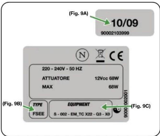
(Fig. 9)
PARTS LIST
| A RECTANGULAR TO ROUND DUCTING ADAPTOR SPS-75000081020 | ||
| B BOTTOM/SIDE COVER COLLAR SPS-75070102735 | ||
| C | BOTTOM/SIDE EXIT PLATE SPS-75070100094 | |
| D | FRONT/REAR VENT ADAPTOR - 58 MODEL SPS-75070100311 | |
| D | FRONT/REAR VENT ADAPTOR - 88/118 MODEL SPS-75070100071 | |
| E | FRONT/REAR VENT COVER PLATE SPS-75059000082 | |
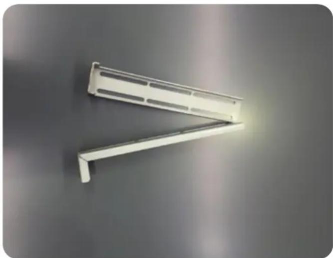
| F | UPRIGHT FIXING BRACKETS SPS-75070100112 | |
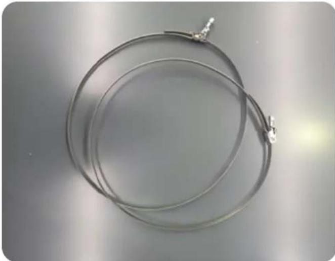
| G | UNIVERSAL RING CLAMP URC25-215 | |
| H | 150MM TO 200MM DUCT EXPANDER GDR 150/200 | |
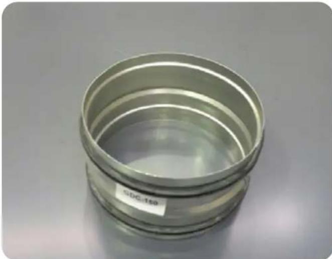
| I | 150MM DIAMETER CONNECTOR PIECE GDC-150 | |
| J | 200MM DIAMETER CONNECTOR PIECE GDC-200 | |
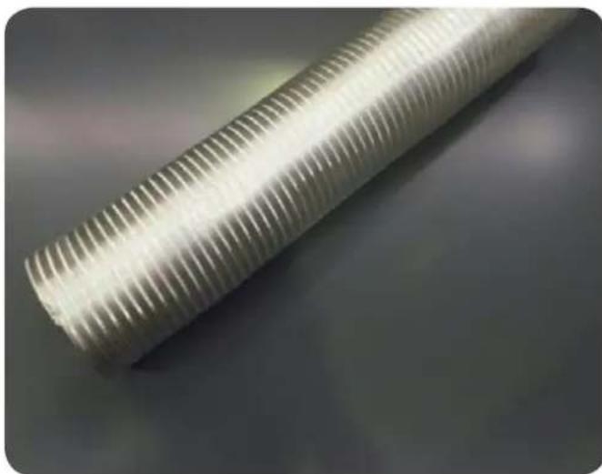
| K | K.1 - DUCTING 150MMK.2 - DUCTING 200MM | SRPRO 30/150SRPRO 30/200 |
PARTS LIST - INCLUDED PIECES
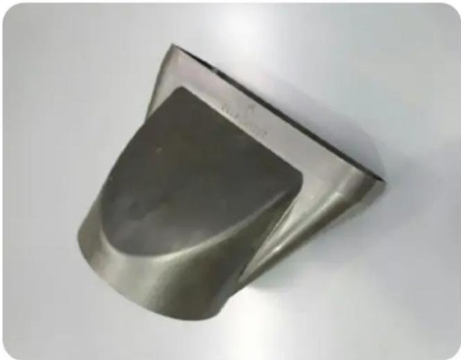
PART A
Rectangular to round ducting adaptor SPS-75000081020
natural_image
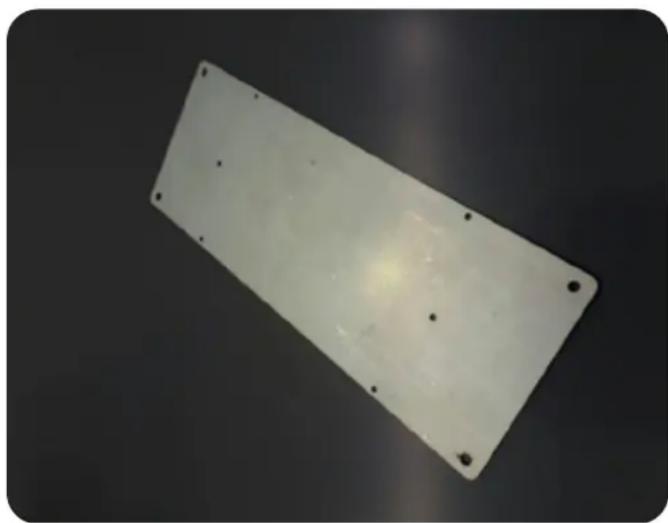
Metallic 3D object with a smooth, curved surface and a dark central area, isolated on a plain white background (no text or symbols visible)PART C
Bottom/side exit connector SPS-75070100094
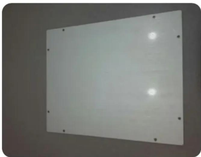
natural_image
White rectangular metal plate with four small holes, placed on a dark surface (no text or symbols visible)Front/rear vent cover plate SPS-75059000082
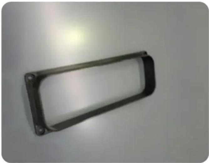
natural_image
Plain white rectangular panel with corner holes and a glossy surface, no text or symbols visible.PART B
Bottom/side cover collar SPS-75070102735
natural_image
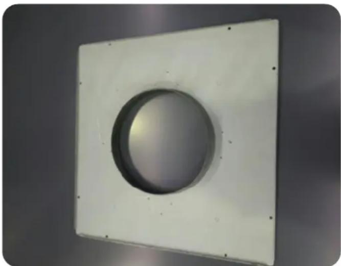
Metal bracket with rounded corners and mounting holes, isolated on plain background (no text or symbols)PART D
Front/rear vent adaptor SPS-75070100311 (For 58 Model) SPS-75070100071 (For 88/118 Model)
natural_image
White square panel with a circular recessed recess, mounted on a plain surface (no text or symbols visible)PART FPART E
Upright fixing brackets SPS-75070100112
natural_image
White metal shelf support bracket with angled arm against a plain gray background (no text or symbols)PARTS LIST - OPTIONAL PIECES
To be purchased separately
PART G
Universal ring clamp URC25-215/325
natural_image
Coiled metal wire or cable with a small metallic connector attached, placed on a plain surface (no text or symbols visible)PART I
150mm diameter connector piece GDC-150
natural_image
Stacked metallic cylindrical component with visible internal structure and label 'SDG-150' (no other text or symbols)Part K.1 / K.2
Semi rigid aluminium ducting 150mm / 200mm SRPRO 30/150 or SRPRO 30/200
natural_image
Close-up of a coiled, translucent plastic tube with radial ridges (no text or symbols visible)PART H
150mm to 200mm Duct expander GDR 150/200
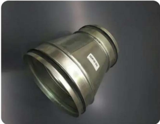
natural_image
Metal pipe fitting with a label showing 'CABO' and '2014' on its side (no other text or symbols visible)PART J
200mm diameter connector piece GDC-200
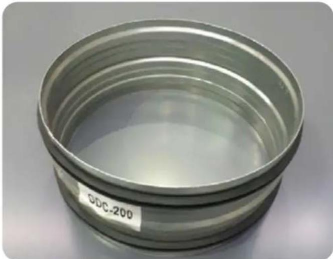
natural_image
Close-up of a metallic cylindrical component with visible internal layers and a label reading 'ODC-200' on the side (no other text or symbols)WIRING DIAGRAMS
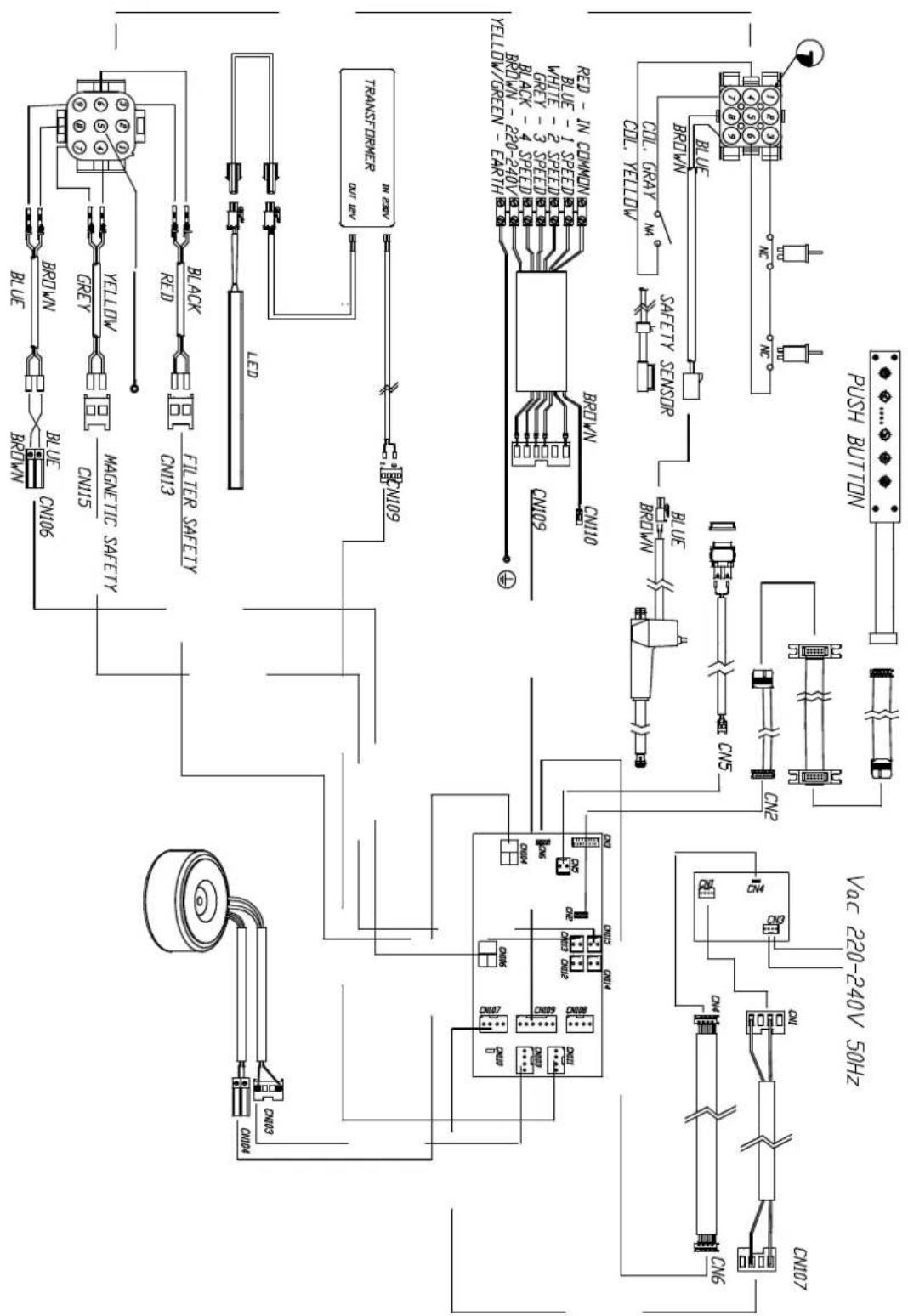
www.arisit.com
www.siriusbrand.com
ARISIT PTY LIMITED (Australia)
ABN 23 091 515 294
40-44 Mark Anthony Drive
Dandenong South VIC 3175
P: Sales & Service: 1300 762 219
F: Sales & Service: (03) 9768 0838
E: arisit@arisit.com

Year
Warranty
when Sirius ducting is used.
Full replacement warranty on parts and labour. Check website for T&Cs.
10 year warranty on SEM motors.
Sirius Hocos and ducting products are only available from our select group of Sirius Professional Stockers nationwide. For the lates, list of Sirius Stockists near you, please refer to www.siriusbrand.com
All efforts have been made to ensure that the information provided in this brochure is correct at the time of printing. Due to continuous product improvement and ongoing development, Sirius
reserves the right to make changes to the products and technical data without prior notice. Some products appearing in this brochure may
be for illustrative purposes only. Diagrams are indicative measures only. Prior to commencing
chically scholars the special citizenship on
be referred to at www.sinusrand.com
- Congratulations on your purchase!
- Thank you for choosing a Sirius product.
- SDD2ELEMTC FLUSH TOP
- TO THE ATTENTION OF THE USER
- WARNING
- SAFETY INSTRUCTIONS
- INSTALLATION GUIDELINES FOR GAS COOKTOP APPLICATIONS
- APPLIANCE DIAGRAMS
- DUCTING TYPES
- BEFORE YOU INSTALL
- INSTALLING THE RANGEHOOD
- STEP 1:
- INSTALLATION INSTRUCTIONS
- SIDE OR BOTTOM VENTING
- STEP 2:
- STEP 3:
- STEP 4:
- STEP 5:
- STEP 6A: Ducting to SEM 11 motor (150mm ducting)
- STEP 6A: Ducting to SEM 21 motor (150mm ducting)
- STEP 6B: Ducting to SEM 71 motor (200mm ducting)
- For SEM 81 motor with SDD2ELEMTC88/118 - 200mm option only.
- INSTALLATION INSTRUCTIONS FOR SEM 11, SEM 21, SEM 71, SEM 81
- FRONT OR REAR VENTING
- Ducting to DDFMEL motor (internal motor)
- DUCTING FROM MOTOR TO WALL VENT: (SEM 11 and SEM 81)
- ELECTRICAL CONNECTION
- NOTE
- This appliance complies with the European Directives 2006/95/EC (Low Voltage Directive) and 2004/108/EC (Electromagnetic Compatibility).
- The downdraft connection to the electrical network must be carried out only by professional and qualified technicians.
- If the rangehood presents any anomaly, disconnect the appliance or remove the fuse corresponding to the appliance power disconnecting line.
- HOW THE RANGEHOOD WORKS
- A: Light ON/OFF key
- B: ↑↓ ON/OFF key
- C: — Decrease fan speed key
- D: Fan speed Indicators
- E: + Increase fan speed key
- F: 10 Minute shut-off timer
- Automatic turn off:
- Grease filters saturation:
- Calibration:
- Stand-by:
- Safety close function:
- CLEANING THE RANGEHOOD
- CAUTION
- TROUBLESHOOTING
- REPLACING THE LIGHT
- AFTER SALES SERVICE
- PARTS LIST - INCLUDED PIECES
- PART A
- PART C
- PART B
- PART D
- PART FPART E
- PARTS LIST - OPTIONAL PIECES
- To be purchased separately
- PART G
- PART I
- Part K.1 / K.2
- PART H
- PART J
- WIRING DIAGRAMS
Brand : SIRIUS
Model : SDD2ELEMTC88
Category : Range hood