
SWRGM-47 - Car audio interface CRUX - Free user manual and instructions
Find the device manual for free SWRGM-47 CRUX in PDF.


| Product Type | GPS Navigation Device |
| Brand | CRUX |
| Model | SWRGM-47 |
| Display Size | 4.7 inches |
| Display Resolution | 480 x 272 pixels |
| Dimensions (W x H x D) | Approx. 12.5 x 8.3 x 1.5 cm |
| Weight | Approx. 200 g |
| Power Source | Rechargeable lithium-ion battery |
| Battery Life | Up to 4 hours |
| Charging | USB cable (5V, 1A) |
| Internal Storage | 8 GB flash memory |
| Map Coverage | Preloaded maps of Europe |
| Map Updates | Free lifetime map updates |
| Navigation Features | Turn-by-turn directions, voice guidance, Points of Interest |
| Connectivity | Bluetooth for hands-free calling |
| Mounting | Windshield suction cup mount included |
| Cleaning | Wipe with a soft, dry cloth |
| Safety Warning | Do not operate while driving; mount securely |
| Spare Parts Available | Replacement charger, mount, and USB cable |
| Repairability | Battery can be replaced by authorized service |
| Warranty | 1 year limited warranty |
| Operating Temperature | 0°C to 45°C |
Frequently Asked Questions - SWRGM-47 CRUX
User questions about SWRGM-47 CRUX
0 question about this device. Answer the ones you know or ask your own.
Ask a new question about this device
Download the instructions for your Car audio interface in PDF format for free! Find your manual SWRGM-47 - CRUX and take your electronic device back in hand. On this page are published all the documents necessary for the use of your device. SWRGM-47 by CRUX.
USER MANUAL SWRGM-47 CRUX
- Retains factory features in select GM IOA & IOB vehicles while functioning with an aftermarket radio.
- Pre-programmed to retain factory Steering Wheel Controls.
- iPhone Voice Recognition (VR) feature from SWC on select radios.
- Supports Pick Up/End Call, Pick up and Toggle between 1st and 2nd incoming call, AVRCP Track, Seek.
- Supports Non Amplified Systems
- Retains factory OnStar®
- Retains chime functions.
- Retains factory backup camera.*
- Retains factory backup sensors / park assist system.
- EIA color coded wiring for easy installation.
NOTE:
Does not retain the factory backup camera on models that show the camera image on the rear-view mirror.
PARTS INCLUDED:

natural_image
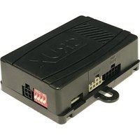
Four electronic components: a black rectangular device, three colored cable with connectors, and a black wire with terminal connector (no visible text or symbols)SWRGM-47 MODULE SWRGM-47 HARNESS SWC CABLES ANTENNA ADAPTER
INSTALLATION DIAGRAM:

flowchart
graph TD
    A["TO FACTORY HARNESS"] --> B["16-Pin Black Connector"]
    B --> C["CRUX"]
    C --> D["See page 2 for Audio connection options"]
    D --> E["Aftermarket RADIO SELECTOR (See Chart)"]
    E --> F["3.5MM SWC CABLES (Option A or B)"]
    F --> G["LED LIGHT"]
    F --> H["LED MODULE FEEDBACK"]
    F --> I["Option A: Cap or insulate if not being used"]
    F --> J["Option B: Insulate with tape if not being used"]
    style A fill:#f9f,stroke:#333
    style B fill:#ccf,stroke:#333
    style C fill:#cfc,stroke:#333
    style D fill:#fcc,stroke:#333
    style E fill:#ffc,stroke:#333
    style F fill:#fcc,stroke:#333
    style G fill:#cff,stroke:#333
    style H fill:#ffc,stroke:#333
    style I fill:#fcc,stroke:#333
    style J fill:#cff,stroke:#333

rev.0705231 of 4
DIP SWITCH SETTINGS:
AFTERMARKET RADIO DIP SWITCH SETTINGS:
NOTE: For Atoto, Blaupunkt, Dual, Farenheit, Power Acoustik, Soundstream, and most off-brand radios, check the aftermarket radio's manual to see if the SWC buttons need to be programmed.
4-PIN SWC CABLE
Use the proper 3.5MM to 4-Pin SWC cable for the aftermarket radio you are using.
OPTION A is used for ALPINE, CLARION, JVC, and KENWOOD units (Blue/Yellow wire is attached) OPTION B is used for ATOTO, BLAUPUNKT, BOSS, DUAL, FARENHEIT, JENSEN, POWER ACOUSTIK, PIONEER, SONY, SOUNDSTREAM and Most Off-Brand Radios.
NOTE: Cap or insulate the 3.5mm plug or Blue/Yellow wire if not being used.
For aftermarket radios that have wires for SWC connections, cut off the 3.5mm plug on the Crux SWC Cable (option B) and connect the SWC wires as follows:

natural_image
Pure diagram of a mechanical tool or connector without any text, numbers, or symbolsRED to SWC Key 1
WHITE to SWC Key 2
SHIELD to SWC Ground
Note that there are some radios that only have SWC1 and SWC2, in this case “shield” does not need to be connected.
SELECTING THE AUDIO SYSTEM:
If the vehicle is equipped with an amplified audio system, the SWRGM-47 has a built-in audio level adaptor that outputs the proper audio level from the aftermarket radio to the factory amplifier. To use this feature, plug in the male 8-pin connector on the SWRGM-47 harness to the GRAY female 8-pin connector on the SWRGM-47 module. The module is also labeled "Bose" and "Non Bose" to avoid confusion. (see picture below)
If the vehicle is NOT equipped with a factory amplified system, plug in the male 8-pin connector to the BLACK female 8-pin on the SWRGM-47 module.

natural_image
Back view of a computer monitor showing internal components and red arrows pointing to ports (no readable text or symbols)NON BOSE
(Non-Amplified)
Connection
BOSE
(Amplified)
Connection
BACKUP CAMERA TROUBLESHOOTING:
Problem: The aftermarket radio does not show the reverse camera image when the vehicle is in reverse.
NOTE: Some vehicles, the reverse camera image is first displayed on the radio display before appearing on the radio.
Solution: Connect the camera input and output wires together using the radio display harness.
- Locate pins 5, 6, 7, and 8 on the Gray 20-pin harness situated at the rear of the radio display (refer to Figure 1).
- Cut the wires connected to pins 5, 6, 7, and 8 near the connector, while ensuring sufficient wire length remains for potential reconnection if the original radio is reinstalled.
- The loose, severed wires originating from the connector are not required. However, the remaining cut wires within the harness must be interconnected as follows (see Figure 2):
- Join Pin 5 to Pin 7.
- Then also join Pin 6 to Pin 8.
- Establish a connection between the Reverse Camera output connector of the SWRGM-47 HAR and the Reverse Camera input on the aftermarket radio
20 Pin Radio Display Connector (Pin Side View)

20 Pin Radio Display Connector (Top View)

CHIME VOLUME ADJUSTMENT:
The SWRGM-47 has a potentiometer to adjust the chime volume. It is set at half way by default. To adjust the volume, simply use a suitable screw driver and turn the potentiometer clockwise to increase the volume and counter-clockwise to decrease the volume.
Chime
Volume
Adjustment

natural_image
Close-up of a black plastic electronic device casing with a red arrow pointing to a small component (no text or symbols visible)VEHICLE APPLICATIONS:
CHEVROLET
2016-2018 Chevrolet Camaro With 7" Screen (IOB)
2016-2017 Chevrolet Cruze With 7" Screen (IOA)
2018 Chevrolet Cruze With 7" Screen (IOB)
2016-2017 Chevrolet Malibu With 7" Screen (IOA)
2018 Chevrolet Malibu With 7" Screen (IOB)
2016-2018 Chevrolet Silverado With 7" Screen (IOB)
2019 Chevrolet Silverado Classic With 7" Screen (IOB)
2016-2017 Chevrolet Silverado HD With 7" Screen (IOB)
2017 Chevrolet Sonic With 7" Screen
2017-2018 Chevrolet Spark With 7" Screen
2017 Chevrolet Trax With 7" Screen (IOA)
GMC
2017 GMC Acadia With 7" Screen (IOB)
2016-2017 GMC Sierra With 7" Screen (IOB)
2016-2017 GMC Sierra HD With 7" Screen (IOB)

2017 Chevy Silverado with 7" Display


Brand : CRUX
Model : SWRGM-47
Category : Car audio interface