
PTC-400C - Camera Elmo - Free user manual and instructions
Find the device manual for free PTC-400C Elmo in PDF.


| Product Type | Document Camera (Visual Presenter) |
| Brand | Elmo |
| Model | PTC-400C |
| Dimensions (H x W x D) | Approx. 350 x 200 x 150 mm |
| Weight | Approx. 1.5 kg (3.3 lbs) |
| Power Supply | AC adapter 100-240V, 50/60Hz |
| Image Sensor | 1/3-inch CMOS |
| Maximum Resolution | 1920 x 1080 (Full HD) |
| Optical Zoom | 12x |
| Digital Zoom | Up to 8x |
| Connectivity | USB 2.0, HDMI output, VGA input/output |
| Lighting | Built-in LED lamps |
| Image Capture | Yes, via software or button |
| Video Recording | Yes, up to 1080p |
| Image Modes | Text, Photo, Negative, Film |
| Storage | Internal memory, SD card slot |
| Included Accessories | AC adapter, USB cable, instruction manual |
| Warranty | Limited 1 year |
| Maintenance | Clean lens with soft, dry cloth; avoid liquids |
| Safety | Use only supplied adapter; keep away from water |
| Spare Parts Availability | Lamp, power supply, remote (sold separately) |
| Repairability | Service by authorized technicians |
| General Information | Compatible with Windows/Mac, includes presentation software |
Frequently Asked Questions - PTC-400C Elmo
User questions about PTC-400C Elmo
0 question about this device. Answer the ones you know or ask your own.
Ask a new question about this device
Download the instructions for your Camera in PDF format for free! Find your manual PTC-400C - Elmo and take your electronic device back in hand. On this page are published all the documents necessary for the use of your device. PTC-400C by Elmo.
USER MANUAL PTC-400C Elmo
Please read this instruction manual carefully before using this PTC-400C and keep it for future reference.
IMPORTANT SAFETY INSTRUCTIONS
- Read these instructions.
- Keep these instructions.
- Heed all warnings.
- Follow all instructions.
- Do not use this apparatus outdoors.
- Do not use this apparatus near water.
- Clean only with dry cloth.
- Do not install near heat sources such as radiators, heat registers, stoves or other apparatus (including amplifiers) that produce heat.
- Do not touch this apparatus during lightning storms.
- Unplug when unused for long periods of time.
- Refer all servicing to qualified personnel. Servicing is required when the apparatus has been damaged in any way, such as power-supply cord or plug is damaged, liquid has been spilled or objects have been fallen onto the apparatus, the apparatus has been exposed to rain or moisture, does not operate normally, or has been dropped.
WARNING: Handling the cord on this product or cords associated with accessories sold with this product, will expose you to lead, a chemical known to the State of California to cause birth defects or other reproductive harm. Wash hands after handling.

CAUTION
RISK OF ELECTRIC SHOCK DO NOT OPEN

CAUTION : TO REDUCE THE RISK OF ELECTRIC SHOCK.
DO NOT REMOVE COVER (OR BACK).
NO USER SERVICEABLE PARTS INSIDE. REFER SERVICING TO QUALIFIED SERVICE PERSONNEL.

The lightning flash with arrowhead symbol, within an equilateral triangle, is intended to alert the user to the presence of uninsulated "dangerous voltage" within the product's enclosure that may be of sufficient magnitude to constitute a risk of electric shock to persons.

The exclamation point within an equilateral triangle is intended to alert the user to the presence of important operating and maintenance (servicing) instructions in the literature accompanying the appliance.
CAUTION
- Do not use any power supply other than specified.
WARNING
TO REDUCE THE RISK OF FIRE OR ELECTRIC SHOCK, DO NOT EXPOSE THIS APPLIANCE TO RAIN OR MOISTURE.
* The CAUTION label is attached on the base of product.
INFORMATION
This equipment has been tested and found to comply with the limits for Class B digital device, pursuant to Part 15 of the FCC Rules. These limits are designed to provide reasonable protection against harmful interference when the equipment is operated in a commercial environment.
This equipment generates, use, and can radiate radio frequency energy and, if not installed and used in accordance with the instruction manual, may cause harmful interference to radio communications. Operation of this equipment in a residential area is likely to cause harmful interference in which case the user will be required to correct the interference at his own expense.
USER-INSTALLER
CAUTION: Your authority to operate this FCC verified equipment could be voided if you make changes or modifications not expressly approved by the party responsible for compliance to Part of the FCC Rules.
HANDLING PRECAUTIONS
This Camera has no power switch. When checking and maintaining this Camera, be sure to turn OFF the power supply to the main unit beforehand.
This Camera is designed only for use indoors. Do not use this Camera out of doors.
■ Do not leave the Camera under direct sunlight or by heater, or the Camera may be discolored, or damaged.
■ Do not place the Camera in any humid, dusty, windy or vibrating location. Use the Camera in the following environmental condition:
Temperature: -10^ 40^ (14^ 104^)
Humidity: 30% \~ 90% (No condensation)
■ Use a soft, dry cloth for cleaning. Do not use any volatile solvent, such as thinner or benzin.
■ Do not directly point the camera lens into the sun, or the camera may be damaged.
■ Caring for the batteries:
- If the Camera is not used for long time, take out the batteries from the case.
- Do not use rechargeable Ni-Cd batteries.
- Do not use new and old batteries, or batteries of different type together.
- Do not try to recharge or short-circuit the batteries.
■ This Camera is designed only for installation to the ceiling.
When installing this Camera, use only the dedicated fixing plate, refer to the pages 9 to 13 of this manual, and carefully check the safety, such as falling prevention.
CONTENTS
IMPORTANT SAFETY INSTRUCTIONS ....1
HANDLING PRECAUTIONS ....3
- PART NAMES AND FUNCTIONS....5
- WIRELESS REMOTE CONTROLLER....7
- SETTING UP 9
- OPERATION PROCEDURES ......14
[1] Power supply to the Camera 14
[2] Turning ON/OFF of the Camera power 14
[3] Operating PAN/TILT 15
[4] Lens operation....15
[5] Preset operation ...... 17
[6] External unit control....18
- THE ID NUMBER (REMOTE ID) SETTING ......19
- SETTING IN THE OSD (ON-SCREEN DISPLAY) MENU……20
- SETTING OF ALARM IN-OUT 28
[1] Alarm input ......28
[2] Alarm output ......28
- SETTING OF RS-485 29
[1] Setting the terminating resistance ……29
[2] Setting the ID address 29
- SETTING OF VARIOUS MODES 30
[1] Initializing the settings 30
- TROUBLESHOOTING HINTS 31
- SPECIFICATIONS....33
2 SUPPLIED ACCESSORIES....35
3 OPTIONS ....36
1. PART NAMES AND FUNCTIONS
- Main unit
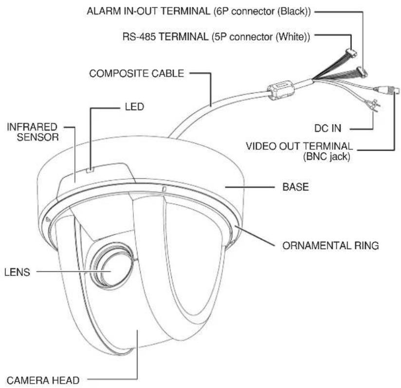
● Wireless Remote Controller
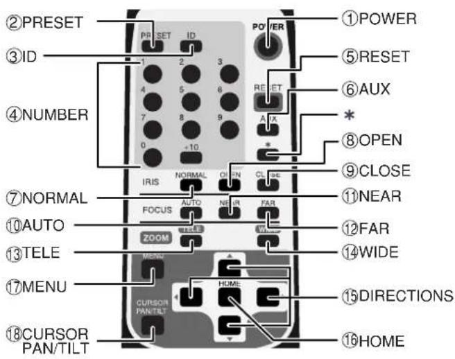
Note: The “*” button is not used for normal operation.
| Button Name Function Ref. Page | ||||
| 1 | POWER To turn ON/OFF the Camera power. P.14 | |||
| 2 | PRESET To register the preset position. P.17 | |||
| 3 | ID To set the ID | No. when multiple Cameras are used. P.19 | ||
| 4 | NUMBER To set the preset position and the ID No. P.17 | |||
| 5 | RESET To readjust the position of the Camera head. P.15 | |||
| 6 | AUX Alarm signal is outputted from ALARM OUT terminal (2). Prior P.18 setting of the OSD mode is required. | |||
| 7 | IRIS | NORMAL | To return the iris to the factory setting automatically. | P.16 |
| 8 | OPEN | To open the iris. | P.16 | |
| 9 | CLOSE | To close the iris. | P.16 | |
| 10 | FOCUS | AUTO | To adjust the focal point automatically to maintain it in the “in focus” status. | P.16 |
| 11 | NEAR | To move the focal point near. | P.16 | |
| 12 | FAR | To move the focal point far. | P.16 | |
| 13 | ZOOM | TELE | To zoom in (TELE) the image. | P.15 |
| 14 | WIDE | To zoom in (WIDE) the image. | P.15 | |
| 15 | DIRECTIONS | To change the Camera head direction by operating the cursor on the OSD. | P.15, 20 | |
| 16 | HOME | To move the Camera head direction by operating the cursor on the OSD. | P.15, 20 | |
| 17 | MENU | To turn ON/OFF the OSD display. In the hierarchical menu, the screen immediately before appears. | P.19, 20 | |
| 18 | CURSOR PAN/TILT | To suspend the menu operation. | P.20 | |
2. WIRELESS REMOTE CONTROLLER
Point the infrared emitter of the wireless remote controller to the infrared sensor located on the front of the Camera main unit, and press the button of the intended operation.
For the receivable range, refer to the below figures.
● Receivable range
Distance : Within approx. 7m from the infrared sensor front
Angle : Within approx. 60° right and left, approx. 10° above and approx 30° below from the infrared sensor front
Side view Bottom view
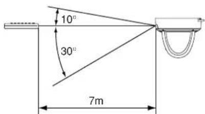

Note: The infrared sensors may receive the infrared rays only within a narrower receivable range or may not receive them at all depending on the ambient environment, such as being placed under the sunlight or near an inverter fluorescent lamp. In such case, relocate the installation place of the receiving side or block off the sunlight.
● Precaution for the battery
Remove the battery case cover by pressing downward on the [] mark part in the direction as indicated by the arrow.
Install 2 pcs. of batteries (type R03, AAA) into the case in the direction as indicated there.
Note: Install the batteries with the proper to and to polarity.
Note: For dry cells, be sure to use the size AAA.
Note: Change the batteries at least once a year or when even necessary.
Note: The supplied batteries supplied with the Camera are only for use in initially confirming the operation of the Camera. It is not guaranteed that these batteries will work effectively for the indicated period.
- When multiple Cameras are operated through the wireless remote controller
Refer to "5. THE ID NUMBER SETTING" on P. 19.
3. SETTING UP
[1] Installation
Note: When carrying the Camera, be sure to hold the base.
Note: Do not turn the Camera head in the PAN-TILT direction by hand, or the Camera head could be broken.
(1) Mounting the Fixing Plate
- Make mounting holes and a cord hole in the place (ceiling) to which this Camera is installed.

WARNING: The total mass of the main unit and fixing plate is approx. 900g. Check whether the ceiling to which the Camera is installed is strong enough to hold the total mass of the main unit and fixing plate. If not, the Camera could fall, causing injury.
- Lock the fixing plate (supplied) firmly with 4 fixing screws (not supplied).
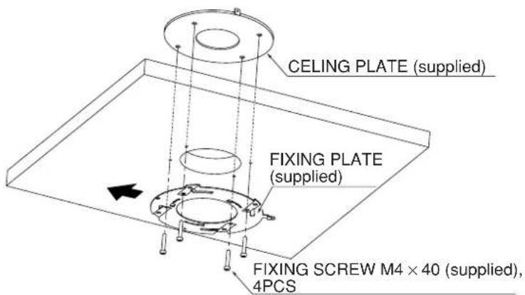
WARNING: Fasten the fixing screws of the fixing plate firmly, or the Camera could fall, causing injury.
(2) Mounting the Camera to the Fixing Plate
- Match the [ ] mark on the fixing plate with the [ ] mark on the back face of the main unit, set the tabs (3 locations) of the back face of the main unit in the mating cuts (3 locations) of the fixing plate, and turn the main unit clockwise by 25° (Refer to A)


(3) Mounting the Safety Wires
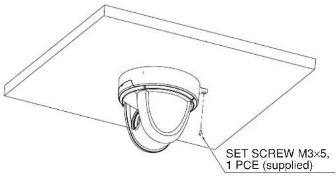
- Loop up one end of the Safety Wires through the respective safety wire looping holes made on the Ceiling Plate, and then loop up the other end of the same around the beams or anything that is used to mount ceiling tile channel for structure safety.

- Lock the Camera and the fixing plate with the set screws (supplied).
[2] Drawing the Composite Cable from the Camera Back Face
(1) Cut off the blank cover from the back face of the Camera base with pliers or the like, and draw the composite cable from the back face of the Camera.

- Connection of the Camera

flowchart
graph TD
    A["VIDEO CABLE (commercial item, BNC, co-axial)"] --> B["VIDEO OUT"]
    B --> C["DC IN (DC 12V (DC11V-16V))"]
    C --> D["COMPOSITE CABLE (integral part of the main unit)"]
    D --> E["RS-485 (5P connector (white))"]
    D --> F["ALARM IN-OUT TERMINAL (6P connector (black))"]
    F --> G["RELAY CABLE (supplied)"]
    H["To MONITOR VIDEO IN"] --> I["Video IN"]
    style A fill:#f9f,stroke:#333
    style E fill:#ccf,stroke:#333
    style G fill:#cfc,stroke:#333
RS-485 terminal (5P connector (white))
| Pin No. | Terminal Name Cord Color | |
| 1 | DATA (+) IN | Brown |
| 2 | DATA (-) IN | Red |
| 3 | DATA (+) OUT | Orange |
| 4 | DATA (-) OUT | Yellow |
| 5 | GND | Green |
ALARM IN-OUT terminal (6P connector (black))
| Pin No. | Terminal Name | Cord Color |
| 1 | ALARM IN1 | Blue |
| 2 | GND | Purple |
| 3 | ALARM IN2 | Gray |
| 4 | GND | White |
| 5 | ALARM OUT1 | Black |
| 6 | ALARM OUT2 | Pink |
Note: When wiring, note the following:
- For the RS-485 ALARM IN-OUT cable, insulate the bare conductor part not to be exposed after wiring.
- For the video cable, keep the BNC connector (metal part) away from any other metal material.
[1] Power supply to the Camera
The Camera has no POWER switch. The power supply to the Camera is turned ON when 12VDC is inputted to the DC IN terminal.
When power is supplied to the Camera, the Camera turns to the right and then to the center automatically (viewed from the front), returning the Camera position to the position set in advance.
[2] Turning ON/OFF of the Camera power
(1) Turning OFF the Camera
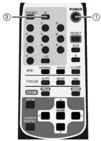
- When the Camera is ready for operation through the wireless remote controller and ① POWER button is pressed, the Camera power is turned OFF. (However, even after the Camera is turned OFF, power is still being supplied to the Camera as power supply to the Camera is not OFF.)
- The image disappears, and the LED on the Camera lights up in red. Now, no buttons on the wireless remote controller are functional other than ① POWER button and ⑧ button.
- When the TIMER OFF function is ON (refer to the settings in the OSD (On-Screen Display) Menu screen on P.21), Camera power is turned OFF automatically upon the lapse of the set time.
(2) Turning ON the Camera
- When the Camera is OFF and ① POWER button is pressed, the Camera power is turned ON.
- The image appears, and the LED on the Camera goes out. Now, the Camera is ready for operation of all functions through the wireless remote controller.
- If the ID number is changed, the Camera power may not be turned ON. In such case, redo the ID number setting, and press ① POWER button.
[3] Operating PAN/TILT

- While watching the screen, press any of ⑮ ▲ ▼◀▶ (UP, DOWN, LEFT, RIGHT) direction buttons for the direction in which you want to watch the image.
• To change the direction minutely, jog the direction button. To change the direction largely, hold down the direction button.
- Two operation modes are available according to the speed: AUTO mode changing the speed according to the zoom position, and MANUAL mode setting the speed manually. (Refer to the settings in the OSD (On-Screen Display) Menu screen on P.26)
- When ⑯ HOME button is pressed, the Camera turns to the front (and the lens moves to the WIDE end) according to the factory settings. The home position can be set freely with the preset No. "0." (Press ② PRESET button and then press ⑨ button.) After setting, when ④ 0 button or ⑯ HOME button is pressed, the home position is loaded. (Refer to P. 17)
- If the Camera direction is changed manually by mistake, press ⑤ RESET button. Then, the Camera remembers the last PAN/TILT position in memory.
[4] Lens operation

(1) Zoom operation
• The object is zoomed in (appears larger in the screen) when ⑬ TELE button of ZOOM is pressed, or zoomed out (appears smaller in the screen) when ⑭ WIDE button of ZOOM is pressed.
- When ⑬ TELE button or WIDE button is held down for over one second, the zoom speed increases.
(2) Focus operation
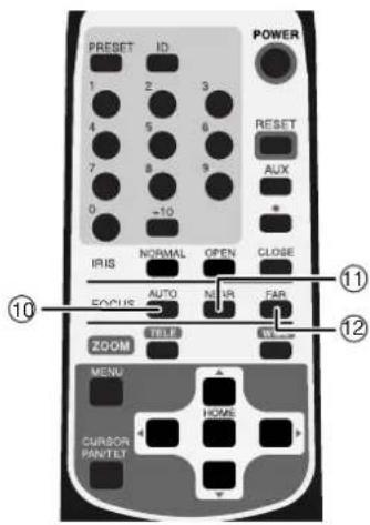
- When AUTO button of FOCUS is pressed, the FULL AUTO FOCUS status is established. However, focusing may be difficult for such objects as listed below.
■ Objects with no contrast between light and shade, such as white walls and night views
■ Objects reflecting an intensive light
■ Objects moving fast
■ Objects with many horizontal stripes, such as blinds
■ Objects with vertical fine stripes.
■ Objects viewed through a glass pane with water drops or stains
■ Dark objects
• To adjust the focus manually, press ⑪ NEAR button or FAR button.
When ⑪ NEAR button is pressed, the focus shifts near to you.
When ⑫ FAR button is pressed, the focus shifts far away from you.

(3) Iris
• The iris remains in the AUTO IRIS status (in the Auto Control mode in which the brightness remains unchanged even if the object is changed).
- When ⑧ OPEN button or ⒷLOSE button of the iris is pressed, the brightness changes in the AUTO IRIS status. (The reference level of the AUTO IRIS changes.)
- OPEN button or CLOSE button cannot be held down. To operate the iris continuously, repeat pressing and releasing the button.
- When ⑦ NORMAL button is pressed (in the AUTO IRIS state), the brightness is reset to the standard level.
[5] Preset operation
The Camera head direction, the zoom position, the focus status and the brightness status can be registered. In addition to these items, when [MAIN CONTROL] – [CAMERA2 PRESET] is set to [ON] in the OSD menu, the [CAMERA2] settings can also be registered together (Refer to P. 23). Up to 17 setting can be registered (Nos. 0 – 16). Even if the main unit power is turned OFF, the registered contents are preserved.

(1) Registration in the Preset Contents
- Set the Camera head direction, the zoom position, the focus status and the brightness level. (To register the [CAMERA2] settings together, set [MAIN CONTROL] - [CAMERA2 PRESET] to [ON] in the OSD menu.)
- When ② PRESET button is pressed (once), the LED (light emitting diode) on the main unit blinks in green (at intervals of 0.2 sec). To cancel this step, press ② PRESET button again.
- Then, input the preset No. within 0 through 16 by pressing ④ corresponding one or two of the 0 through +10 buttons. (+10) button is used to input numeric of 10 or larger. For "10," press +10 button and then 0 button.)
- Upon pressing, the LED on the main unit goes out and the registration of the preset contents is completed. (The preset contents already registered, if any, are overwritten.)
- The home position can be registered freely to any position by using the preset No. "0."
(2) Execution of the Preset
- When ④ intended one or two of the 0 through +10 buttons is pressed, the Camera head direction, the zoom position, the focus status and the brightness level are set as per registered. (+10) button is used to input numeric of 10 or larger. For “10,” press +10 button and then 0 button.)
[6] External unit control
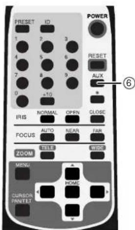
To make AUX button functional, set
[ALARM] - [ALARM OUT2] to [ON] in the OSD menu beforehand.
When ⑥ AUX button is pressed, the external unit connected to the ALARM OUT terminal
<2> is turned ON. To turn it OFF, press ⑥
AUX button again.
5. THE ID NUMBER (REMOTE ID) SETTING
When multiple Cameras are laid out adjacently and operated via the wireless remote controller, the Cameras receiving the infrared rays operates in unison in the same way. When each Camera is allocated with a different ID No., the Camera can be operated selectively when its ID No. is specified via the wireless remote controller. The ID Nos. can be allocated to up to 9 Cameras.

(1) Setting an ID No.
- Turn ON only the camera to be set with an ID No. Turn OFF the other adjacent Cameras. (Unplug the AC adapters of those Cameras from the outlet.)
- Set the remote ID No. to the Camera. (See "6. OSD (On-Screen Display) on P.20) After setting, close the Menu screen by pressing ⑰
MENU button. Then, repeat the ID No. setting for all other Cameras in the same way.
(2) Operating the Cameras selectively
- Press Ⓐ button, and the LED's of all adjacent Cameras will start blinking (at intervals of 0.4 sec). To cancel this, press ③
ID button again. Then, press ④ through ⑨ buttons, and the LED's will go out, and selective operation by specifying the ID No. will be ready. Now, only the selected Camera can be operated via the wireless remote controller.
(3) Canceling the specific ID of the Cameras
- Hold down ③ ID button for over 2 sec, and the blinking LED on the Camera will light up. Then, unhand ③ ID button. Now, the selective operation has been cancelled, and all adjacent Cameras start operation via the wireless remote controller.
- Even if the Camera is rebooted, the selective operation by specifying the ID No. is cancelled.
6. SETTING IN THE OSD (ON-SCREEN DISPLAY) MENU

Each time MENU button is pressed, the OSD menu is turned ON/OFF. In the hierarchical menu, when ⑰ MENU button is pressed, the screen immediately before appears.
In the OSD menu, buttons and play
⑯ HOME button are used for menu operation. To suspend the menu operation and perform the PAN-TILT operation, press ⑱ CURSOR/PAN-TILT button.
To resume the menu operation, press ⑱ CURSOR/PAN-TILT button again.
- OSD menu
| [1] MAIN CONTROL | |||
| Name | Function | Factory Settings | |
| 1 | TITLE | To turn ON/OFF the character display in the bottom of the screen. | OFF |
| SELECT | To select the title [CAMERA/PRESET] to be character-displayed (enabled only when the above [TITLE] is ON).[PRESET]: Preset position names 1 – 16[CAMERA]: Camera main unit name. | CAMERA | |
| 2 | SET INDICATE | To turn ON/OFF the screen display of the preset position upon its registration.The No. of the registered preset position is screen-displayed for seconds. | OFF |
| 3 | RS-485 ID 1 | To set the ID addresses [1 – 223] for the RS-485 communication.Up to 223 Cameras can be controlled selectively. | |
| 4 | RS-485 END | To turn ON/OFF the settings of the RS-485 terminating resistance contained in the Camera main unit.(For the telecommunication equipment to be connected to the RS-485 interface, a terminating resistance should be attached to both ends of the equipment having the longest route to prevent signal damping.) | OFF |
| 5 | REMOTE ID | To set the ID No. [1 – 9] for the Camera main unit for selective operation by using the wireless remote controller. When the ID No. is not to be set, input [0]. Up to 9 Cameras can be controlled selectively with one wireless remote controller. | 0 |
| To set the time of the Low Power Consumption mode [OFF, 40min, 1h, 2h, 3h, 4h, 5h] If it has passed over this set time with no operation, the Camera power will be turned OFF automatically. (When 1 POWER button is pressed again, the Camera power is turned ON again.) | OFF6 OFF TIME | ||
| 7 | AUTO RETURN | To set the time of automatic return to the home position [OFF, 30s, 1min, 2min, 5min, 10min, 20min, 30min]If it has passed over this set time with no operation after the PAN-TILT-ZOOM operation, the Camera will return automatically to the home position. The home position can be registered freely with the preset No. “0.” | OFF |
| 8 | CAMERA2 PRESET | When this function is set to [ON], the setting of each item of [CAMERA2] can be registered in its preset position.(Set this button to [ON/OFF].) | OFF |
| [2] CAMERA1 | |||
| Name | Function | Factory Settings | |
| 1 | E-ZOOM MAX | To set the maximum magnification [OFF, ×1.5, ×2, ×2.5, ×3, ×4, ×6, ×8, ×16]When 13 TELE button on the wireless remote controller is held down, the optical zoom ×12 enters automatically from its end point into the digital zoom area. | OFF |
| [2] CAMERA1 | |||
| Name | Function | Factory Settings | |
| 2 | HS-SHUTTER | To select the high-speed shutter speed [OFF (1/60s), 1/100s, 1/250s, 1/500s, 1/1000s, 1/2000s, 1/4000s, 1/10000s, 1/20000s, 1/50000s].When [LS-SHUTTER] is [ON], the shutter speed can be selected from [1/60sm 1/100s].If the shimmer of fluorescent lamp is annoying when the shutter speed is set to [OFF (1/60s), set the shutter speed to [1/100s], and the shimmer will be eased. | OFF |
| 3 | LS-SHUTTER | To set the low-speed shutter (electronic sensitivity up) to [ON/OFF]. When the object becomes dark, this function automatically varies the CCD storage time across several fields up to the set maximum level to optimize the brightness of the object. | OFF |
| LS-MAX | To set the maximum number of fields of the low-speed shutter [2fields, 3fields, 4fields, 5fields, 6fields, 8fields, 12fields, 20fields, 40fields, 80fields].If the CCD storage time is set longer, the image frame rate will decrease, and moving object could not be seen well. | 4fields | |
| PRIORITY | To select the image attributes [MOTION (movement), COLOR (color), S/N (fineness)] to be prioritized when [LS-SHUTTER] is selected and the object becomes dark. | MOTION | |
| 4 | ICR OFF | To set the DAY/NIGHT function (IR cut filter removable function)When this function is set to [AUTO], the filter is attached/removed automatically according to the brightness. When the IR cut filter is removed, the color image is switched to B&W image. | |
| 5 | AUTO LEVEL | To select the timing of switching from B&W to color [1 – 15].Particularly when the infrared illumination is intensive, select larger numeric value to prevent hunting. | 5 |
| 6 | INFRARED OFF | To set the infrared illumination using mode to [ON/OFF] To use the infrared illumination, set this function to [ON]. If the infrared illumination is used with this function in the [OFF] status, the image could be out of focus. | |
| 7 | AGC GAIN 8dB | To set the maximum gain of the AGC [0dB, 4dB, 8dB, 16dB, 20dB, 24dB].The AGC is a function of amplifying the signal from the CCD to make the object visible when the object becomes dark. | |
| [3] CAMERA2 | |||||
| Name | Function | Factory Settings | |||
| 1 | BLC OFF | To set the backlight compensation function to [ON/OFF].When there is an intensive light in the background, this function prevents the object from becoming dark. | |||
| BLC MODE | To select the Backlight Compensation Setting mode [AREA/HIST]. | AREA | |||
| About the Backlight Compensation Setting mode | |||||
| AREA | To select the image area of the object that needs an appropriate brightness and weighing according to the selected area. | ||||
| HIST | To make the dark (blackened) part of the image visible regardless of the area. | ||||
| AREA | To select the area [0-4] on the image where the backlight compensation function works when [AREA] is selected. | 4 | |||
| AREA0 | |||||
| AREA4 | AREA2AREA3 | ||||
| AREA1 | |||||
| 2 | AP GAIN | To select the detail compensation level [-5~10] | ±0 | ||
| 3 | ATWB | To select the White Balance Setting mode [ATW, AWC, INDOOR, OUTDOOR, FL-LIGHT, MWB]. | |||
| About the White Balance Setting mode | |||||
| ATW | To adjust the white balance by way of continuous, automatic following.(When the image is in monochrome all over, the white balance may not be matched.) | ||||
| AWC | To adjust the white balance by one-push of button.When [AWC] is selected and6HOMEbutton is pressed, the white balance is adjusted automatically in the then screen status.(This adjustment ends in seconds, and the adjusted value is fixed.) | ||||
| [3] CAMERA2 | ||||
| Name | Function | Factory Settings | ||
| INDOOR | This function is selected when the Camera is used indoors. The color temperature is assumed to be 3200K. | |||
| OUTDOOR | This function is selected when the Camera is used outdoors. The color temperature is assumed to be 6300K. | |||
| FL-LIGHT | This function is selected when the Camera is used with the fluorescent illumination ON. The color temperature is assumed to be 4200K. | |||
| MWB | To change the color tendency as desired. | |||
| MWB-R | To set the red color tendency [-30~+30] when [MWB] is selected. | ±0 | ||
| MWB-B | To set the blue color tendency [-30~+30] when [MWB] is selected. | ±0 | ||
| [4] MASKING | ||||
| Name | Function | Factory Settings | ||
| 1 | MASK | To select [ON/OFF] of the masking function.When there is any part to be masked in the image to be picked up, this function masks such part.(However, during the PAN-TILT-ZOOM operation, mask is not displayed.)After setting the area data, even if [OFF] is selected and the mask display disappears, the area data will not be cleared. | OFF | |
| AREA1-6 | To select [ON/OFF] of the masking for 6 areas, individually, when [ON] is selected in [MASK]When the area to be set is selected from [AREA1-6]and 16HOMEbutton is pressed, the Detail Set window for the selected area appears. | |||
| About the detail setting of [AREA1-6] | ||||
| SIZE | To set the mask size, display the [SIZE] Set window, move the size by using 15▲▼◄► buttons, and then press 16HOMEbutton. | |||
| [4] MASKING | |||||
| Name | Function | Factory Settings | |||
| LOCATION | To set the mask position, display the [LOCATION] Set window, move the position by using 15 ▲▼◀▶ buttons, and then press 16 HOME button | ||||
| SAVE | When the cursor is moved to [SAVE] and 16 HOME button is pressed, the mask data (position, size) is saved and enabled.However, when the rotation angle of TILT is 45° - 135° (±45° from the beneath-facing status of the Camera), the mask data cannot be saved. | ||||
| CANCEL | When the cursor is moved to [CANCEL] and 16 HOME button is pressed, the unsaved mask is disabled, and the image returns to the status before the mask setting. | ||||
| CLEAR | When the cursor is moved to [CLEAR] and 16 HOME button is pressed, the mask in display disappears, and the image falls into the status without the mask setting. | ||||
| [Note] The masking function is not complete since it may make a part to be masked visible depending on the zoom position or Camera direction. Therefore, do not try to mask any confidential information by using this function. | |||||
| [5] TITLE SET | |||||
| Name | Function | Factory Settings | |||
| 1 | CAMERA CAMERA | To register the Camera main unit name. This function is convenient when multiple Cameras are used.Move the cursor to [CAMERA] to make the cursor blink.Go to the character to be set by using the ▶ button.Change the character by using the ▲▼ buttons, and move from character to character by using the ◀▶ buttons. By setting the characters one by one, up to 10 characters can be set. After setting, press 16 HOME button for saving. | -1 | ||
| 2 | PRESET1 -16 HOME | To register all preset position names selectively.Move the cursor to [PRESET1 - 16] to make the cursor blink. Go to the character to be set by using the ▶ button. Change the character by using the ▲▼ buttons, and move from character to character by using the ◀▶ buttons. By setting the characters one by one, up to 10 characters can be set. After setting, press 16 HOME button for saving. | PRESET -1-16, HOME | ||
| [6] PAN TILT | |||
| Name | Function | Factory Settings | |
| 1 | MOTOR SPEED | To select the motor speed setting [AUTO/MANUAL] for the PAN-TILT operation.When [AUTO] is selected, the operation speed varies automatically according to the zoom position.When [MANUAL] is selected, the operation speed can be selected freely. | AUTO |
| SPEED | To select the operation speed [0 – 7] (0: Fastest) when [MOTOR SPEED] is set to [MANUAL]. | 0 | |
| 2 | L/R DIRECTION OFF | To change the direction of the PAN operation left and right. | |
| 3 | DOME COVER OFF | When the Clear Dome Cover (PTC40CL) or the Smoke Dome Cover (PTC40SM), both available on option, is attached, set this function to [ON]. According to the dome cover, this function limits the TILT operation range.(When the dome cover is not attached, set this function to [OFF].) | |
| 4 | PRESET STILL OFF | When this function is set to [ON], the image during the movement between the preset positions becomes static (the image before the movement). In this mode, movement is enabled between the preset positions (including the home position), but the PAN-TILT-ZOOM operation is disabled. This function is useful to mask the images other than the home position image and the preset position images. (However, only when the 5 [PRESET] button is pressed, the image cannot be static.) (Set this function to [ON/OFF].) | |
| 5 | FLIP ANGLE 120 | When the rotation angle exceeds 90^ (the Camera is facing beneath), the image reverses upside down. For example, the ceiling comes to the bottom of the image. In this case, this Camera automatically reverses the image vertically or horizontally.To select the image reverse angle [OFF, 100^ , 110^ , 120^ , 130^ , 140^ ](When the image should not be reserved, set this function to [OFF].) | |
| [7] ALARM | |||
| Name | Function | Factory Settings | |
| 1 | ALARM IN1 | To set the preset position [PRESET1 – 16] for movement in case of input in the ALARM IN terminal <1> | PRESET1 |
| ALRAM LOCK | When this function is set to [ON], as long as the input is in the ALARM IN terminal <1>, other operations are disabled. (Set this function to [ON/OFF].) | OFF | |
| 2 | ALARM IN2 PRESE | T2 set the preset position [PRESET1 – 16 AUTO] for movement in case of input in the ALARM IN terminal <2>. | |
| 3 | ALARM OUT1 0.1s | To select the signal time [OFF, 0.1s, 0.2s, 0.5s, 1s, 2s, 5s] to be outputted from the ALARM OUT terminal <1> in case of input in the ALARM IN terminal <1> or <2> and the completion of the preset operation. | |
| 4 | ALARM OUT2 OFF | When this function is set to [ON], the ALARM OUT terminal <2> is enabled.When 6 AUX button is pressed (once), the alarm signal is outputted from the ALARM OUT terminal <2>.When this button is pressed again, this function is set to [OFF].(Set this function to [ON/OFF].) | |
7. SETTING OF ALARM IN-OUT
[1] Alarm Input
When each of the ALARM IN terminals <1> and <2> are short-circuited to the GND terminal, the Signal IN mode is established, and the Camera moves to the preset position set in the OSD menu beforehand.
(1) Setting of the preset position for the ALARM IN terminals <1>, <2> (Refer to P. 27)
(2) Lock mode when input is in the ALARM IN terminal <1> (Refer to P. 27)
[2] Alarm output
When input is made into either of the ALARM IN terminals <1> and <2> and the preset operation is completed, the alarm signal is outputted form the ALARM OUT terminal <1> for the time set in the OSD menu beforehand.
(1) Setting the time for the ALARM OUT terminal <1> (Refer to P. 27)
(2) Signal specifications for the ALARM OUT terminal <1>
Open collector output: Max. 12V, 30mA
When set so in the OSD menu, the signal output from the ALARM OUT terminal <2>
(EXTERNAL OUT terminal) can be turned ON/OFF by pressing the ⑥ AUX button on the wireless remote controller.
(3) Setting the time for ALARM OUT terminal <2> (Refer to P. 27)
(4) Signal specifications for ALARM OUT terminal <2>
Open collector output: Max. 12V, 30mA
● ALARM IN-OUT terminal (6P connector (black))
| Pin No. | Code Color | Terminal Name | Signaling System | |
| 1 | Blue | ALARM IN1 | IN <1> No-voltage make contact | |
| 2 | Purple | GND | —— | |
| 3 | Gray | ALARM IN2 | IN <2> | No-voltage make contact |
| 4 | White | GND | —— | |
| 5 | Black | ALARM OUT1 | OUT <1> | Open collector output |
| 6 | Pink | ALARM OUT2 | OUT <2> | Open collector output |
Note: When connecting with external equipment, observe the rated range.
8. SETTING OF RS-485
By wiring and connecting the RS-485 terminal of the 5P connector (white) with the RS-485 control, this Camera can be controlled.
By setting the ID address for the RS-485 communication in each Camera, up to 223
Cameras can be controlled by a single PC or controller.
To assure the reliability, connect DATA(+) and DATA(-) with a shielding twist pair wire. To protect the Camera main unit and the controller, be sure to turn OFF all the equipment before starting connection.
● Transmission specifications
- Transmission mode: Synchronous half duplex
• Transmission speed : 9600bps - Start bit : 1 bit
- Stop bit : 1 bit
- Parity bit : None
● RS-485 terminal (5P connector (white))
| Pin No. | Code Color | Signal Name | Signal Function |
| 1 | Brown | DATA(+) | + side: To input the transmitted/received data |
| 2 | Red | DATA(-) | - side: To input the transmitted/received data |
| 3 | Orange | DATA(+) | + side: To output the transmitted/received data |
| 4 | Yellow | DATA(-) | - side: To output the transmitted/received data |
| 5 | Green | GND | GND |
[1] Setting the terminating resistance (Refer to P. 21)
For the telecommunication equipment to be connected to the RS-485 interface, a terminating resistance should be attached to both ends of the equipment having the longest route to prevent signal damping.
Set the terminating resistance contained in the Camera to [ON/OFF] by selecting [MAIN CONTROL] – [RS-485END] in the OSD menu.
[2] Setting the ID address (Refer to P. 21)
Set the ID address for the RS-485 transmission to [1 - 223] by selecting [MAIN CONTROL] – [RS-485ID] in the OSD menu.
For the information of the data format specifications and command list, please contact our dealer.
9. SETTING OF VARIOUS MODES
[1] Initializing the settings
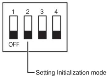
When the 4P DIP switch No. 2 located on the bottom of the main unit is set to [ON] and the Camera power is turned ON, the PAN-TILT settings, the lens settings, the preset settings, and the Camera settings made in the OSD menu are reset to the factory settings. Then, set the DIP switch No. 2 to [OFF].
Note: After initialization, be sure to set the DIP switch No. 2 to [OFF]. If it is left in [ON], each time the Camera power is turned ON, the settings will be initialized and cannot be saved.
Note: For the unused switches of the DIP switch, be sure to set to [OFF].
- Pin assignment
| Pin No. | Normal Operation Function | |
| 1 OFF | Leave in OFF | — |
| 2 OFF | ON OFF To initialize the settings | |
| 3 OFF | Leave in OFF | — |
| 4 OFF | Leave in OFF | — |
●4P DIP switch
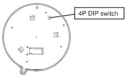
Bottom of the main unit
- TROUBLESHOOTING HINTS
| Symptom | Ref. Page | |
| No image or dark image on the monitor | Is the Camera main unit connected correctly with the monitor with the video cable? Isn't the MONITOR IN terminal of the monitor wrong? | P. 13 |
| Is the DC IN cable connected correctly? | P. 13 | |
| Isn't the DC IN cable or the video cable damaged? Isn't there any disconnection or incomplete contact? | P. 13 | |
| Is the correct voltage (DC12V (DC11V-16V)) supplied to the outlet? | — | |
| Is the iris in proper position? | P. 16 | |
| Isn't the zoom on the TELE side and imaging a dark, monochromatic object? | P. 15 | |
| Isn't the LED lighting in red? If yes, the Camera power should be OFF. | P. 14 | |
| Isn't the OFF TIME function activated, turning OFF the Camera power? (If the Camera power is turned ON without being aware of this and the no-operation status continues, the Camera power will be turned OFF again.) | P. 14, 21 | |
| Is the high-speed shutter set? | P. 21 | |
| Isn't the monitor TV system different from the signal of this Camera (NTSC)? | — | |
| Out of auto focus | Isn't mode the Manual Setting mode? If yes, press the AUTO button to return the mode to the Auto Focus mode. | P. 16 |
| Isn't a flat or fast-moving object shooted? (Some objects are not suitable for the Auto Focus.) | P. 16 | |
| Isn't the infrared illumination intensive? Set [CAMERA1] – [INFRARED] to [ON] in the OSD menu. | P. 22 |
Checking Point
| Symptom | Ref. Page | |
| No operation via wireless remote controller | Isn't wrong ID number set? | P. 19 |
| Check the remaining battery power of the wireless remote controller. | P. 7 | |
| If the sunlight or the fluorescent lamp light of the inverter enters the infrared sensor, the signal from the wireless remote controller could not be sensed normally. If yes, block the light, and then operate the wireless remote controller. | P. 28 | |
| Isn't the 4P DIP switch No. 1 located on the bottom of the main unit set to [ON]? If yes, the wireless remote controller cannot be operated. | P. 30 | |
| Isn't [PAN TILT] – [PRESET STILL] set to [ON] in the OSD menu? If yes, the PAN-TILT-ZOOM operation is disabled. | P. 26 | |
| B&W image | This Camera has the B&W/color switching function. Check the settings. | P. 22 |
| No switching to B&W image | Isn't [CAMERA1] – [ICR] set to [OFF] in the OSD menu? If yes, the DAY/NIGHT function is disabled. | P. 22 |
| Frequent color/B&W screen | Isn't the infrared illumination intensive? Increase the numeric of [CAMERA1] – [AUTO LEVEL] in the OSD menu. | P. 22 |
| Shimmer when imaging fluorescent | When [CAMERA1] – [HS-SHUTTER] is set to [OFF] in the OSD menu, the shimmer will be eased by setting the shutter speed to [1/100s]. (However, since this will change the brightness, the iris operation may be required.) | P. 22 |
| No adjustment of preset position | The Camera head direction may have been changed by hand. Correct the position by pressing the RESET button on the wireless remote controller. | P. 17 |
Checking Point
If the problem still remains after checking the above and apply the remedy, consult our dealer from whom you have purchased the Camera or our branch office or sales office nearest to you.
11. SPECIFICATIONS
- General
| Item Specifications | |||
| Power source | DC12V (DC11V-16V) | ||
| Current consumption | MAX. 1A | ||
| Outside dimensions | Diameter 139mm (5.74in.), Height 121mm (4.76in.) (Projections and fitting plate not included) | ||
| Weight / mass | 1.98lb (Fitting plate included) | ||
| Television system | NTSC system | ||
| Video signal output terminal | Composite video B | NC jack / 75Ω unbalanced 1 | |
| External control terminal | RS-485 5P connector (white) 1 | ||
| ALARM IN-OUT 6P connector (black) 1 | |||
- Lens
| Item Specifications | |
| Optical zoom | Powered12 times |
| Focal length | F = 3.8 - 45.6 mm |
| F No. | F1.6 - 2.7 |
| Field of view (horizontal) | 4.5^ - 52.8^ |
| Iris | Auto (level adjustable) |
| Focus adjustment | Full-auto / Manual |
PAN-TILT
| Item Specifications | |
| PAN range | Left 175°, Right 175° |
| TILT range | Up 15°, Down 195° |
| PAN-TILT speed | Auto / Manual (8 speeds) |
| Preset point | 16 points |
| Auto return to home position | Provided |
| Pan / Tilt movable range limit | Provided (Setting enabled when dome cover is mounted) |
- Camera
| Item Specifications | |
| Image pickup element | 1/4-in CCD |
| Effective picture element | 768 (Horizontal) × 494 (Vertical) |
| Total picture element | 811 (Horizontal) × 508 (Vertical) (410,000 pixels) |
| Minimum illumination | Color: 1 lx (DAY/NIGHT function OFF, 30IRE)B&W: 0.3 lx (DAY/NIGHT function ON, 30IRE) |
| Digital zoom | Max. 16 times |
| Backlight compensation | ON/OFF |
| White balance | Auto / One-push / Manual / Indoor mode / /Outdoor mode / Fluorescent lamp mode |
| Sync. system | Internal synchronization |
| Resolution | Horizontal: 470 TV lines or moreVertical: 360 TV lines or more |
| S/N ratio | 49dB |
| DAY/NIGHT function | Provided |
| Masking function | Provided |
| Image flip (vertical, horizontal) function | Provided |
| AGC gain adjustment | Provided |
| Detail compensation level adjustment | Provided |
| High-speed shutter | Provided (1/60s – 1/50000s) |
| Low-speed shutter (Electronic sensitivity up) | Provided (Max. 80 fields) |
Note: Measured in flat lamp light. The numeric value depends on the light source.
- Others
| Item Specifications | |
| OSD Menu window | Provided (Camera setting) |
| Daisy chain connection (RS-485) | Max. 223 Cameras |
12. SUPPLIED ACCESSORIES
| Name Quantity | |
| Wireless remote controller (RC-PTY) | 1 |
| Battery size AAA | 2 |
| RS-485, Relay cable (5P connector color: White) | 1 |
| ALARM IN-OUT, Relay cable (6P connector color: Black) | 1 |
| Ceiling plate | 1 |
| Main unit set screw M3 × 5 | 1 |
| Fixing plate (for under the roof) | 1 |
| Fixing screw M4 × 40 | 4 |
| Instruction Manual | 1 |
Note: Weight and dimensions are approximate.
Note: Design and specification are subject to change without notice.
13. OPTIONS
| Name |
| Clear dome cover PTC40CL |
| Smoke dome cover PTC40SM |
Note: The specifications are subject to change without notice.
ELMO is a trademark of ELMO CO., LTD.
WARNING:
■ Unauthorized recording of copyrighted, materials, photographs, etc. may infringe on the rights of copyright owners and be contrary to copyright laws.
ELMO CO., LTD.
6-14, Meizen-cho, Mizuho-ku,
Nagoya, 467-8567, Japan
OVERSEAS SUBSIDIARY COMPANIES
U.S.A ELMO USA CORP.
1478 Old Country Road, Plainview, NY 11803-5034
Tel:(516)501-1400 Fax:(516)501-0429
E-mail:elmo@elmousa.com
Web : http://www.elmousa.com
Canada ELMO CANADA CORP.
44 West Drive, Brampton, Ontario L6T 3T6
Tel:(905)453-7880 Fax:(905)453-2391
E-mail : info@elmocanada.com
Web : http://www.elmocanada.com
Germany ELMO (Europe) G.m.b.H
Neanderstr. 18, 40233 Düsseldorf
Tel:(0211)3864-70 Fax:(0211)376630
E-mail : info@elmoeurope.com
Web : http://www.elmoeurope.com
Printed in Japan
6X1PTYC02


- IMPORTANT SAFETY INSTRUCTIONS
- CAUTION
- WARNING
- INFORMATION
- USER-INSTALLER
- HANDLING PRECAUTIONS
- CONTENTS
- PART NAMES AND FUNCTIONS
- WIRELESS REMOTE CONTROLLER
- ● Receivable range
- ● Precaution for the battery
- SETTING UP
- [1] Installation
- Mounting the Fixing Plate
- Mounting the Safety Wires
- [1] Power supply to the Camera
- [2] Turning ON/OFF of the Camera power
- Turning OFF the Camera
- Turning ON the Camera
- [3] Operating PAN/TILT
- [4] Lens operation
- Zoom operation
- Focus operation
- Iris
- [5] Preset operation
- Registration in the Preset Contents
- Execution of the Preset
- THE ID NUMBER (REMOTE ID) SETTING
- Setting an ID No.
- Operating the Cameras selectively
- Canceling the specific ID of the Cameras
- SETTING IN THE OSD (ON-SCREEN DISPLAY) MENU
- - OSD menu
- SETTING OF ALARM IN-OUT
- [1] Alarm Input
- [2] Alarm output
- SETTING OF RS-485
- ● Transmission specifications
- [1] Setting the terminating resistance (Refer to P. 21)
- [2] Setting the ID address (Refer to P. 21)
- SETTING OF VARIOUS MODES
- [1] Initializing the settings
- - Pin assignment
- ●4P DIP switch
- SPECIFICATIONS
- SUPPLIED ACCESSORIES
- OPTIONS
- WARNING:
- ELMO CO., LTD.
- OVERSEAS SUBSIDIARY COMPANIES
Brand : Elmo
Model : PTC-400C
Category : Camera