
MO-1w - Camera Elmo - Free user manual and instructions
Find the device manual for free MO-1w Elmo in PDF.


| Product Type | Wireless Mobile Document Camera (Visual Presenter) |
| Brand | Elmo |
| Model | MO-1w |
| Dimensions (Setup) | W101 x D416 x H338 mm |
| Dimensions (Folded) | W101 x D226 x H28 mm |
| Weight | Approx. 590 g |
| Power Source | DC 5V (AC adapter 100-240V) or USB (min 3.5W) |
| Power Consumption | 7.4 W (USB: 3.5 W) |
| Image Sensor | 1/3.2" CMOS, 2048 x 1536 effective pixels |
| Lens | F2.9 |
| Focus | Auto / Manual, minimum distance 70 mm from lens surface |
| Zoom | Digital max 8x |
| White Balance | Auto, Natural, Fluorescent, Incandescent |
| Image Rotation | Live: 0°/180°, Still: 0°/90°/180°/270° |
| Illumination | White LED lamp (on/off) |
| Wireless Output | 5 GHz, WHDI, up to 10 m; resolutions up to 1080i |
| Input Terminals | RGB (Mini D-sub 15P), HDMI (Type A), USB (Mini B), SD card slot |
| Storage Media | SD/SDHC card (not SDXC), class 6 or higher recommended |
| Operating Temperature | 0°C to 40°C (32°F to 104°F) |
| Cleaning | Unplug, use soft dry cloth; no liquid or aerosol cleaners |
| Safety | Avoid water, unstable surfaces, block ventilation; use only manufacturer-recommended attachments |
| Repairable Period | 8 years after discontinuation of product |
| Compliance | FCC Part 15 Class B, ICES-003, HDMI, WHDI |
| Included Accessories | AC adapter, power cord, USB cable, CD-ROM (Image Mate software), warranty card |
Frequently Asked Questions - MO-1w Elmo
User questions about MO-1w Elmo
0 question about this device. Answer the ones you know or ask your own.
Ask a new question about this device
Download the instructions for your Camera in PDF format for free! Find your manual MO-1w - Elmo and take your electronic device back in hand. On this page are published all the documents necessary for the use of your device. MO-1w by Elmo.
USER MANUAL MO-1w Elmo
All the safety and operating instructions should be read before the appliance is operated.
■ Retain Instructions
The safety and operating instructions should be retained for future reference.
■ Heed Warnings
All warnings on the product and in the operating instructions should be adhered to.
■ Follow Instructions
All operating and use instructions should be followed.
■ Cleaning
Unplug this product from the wall outlet before cleaning. Do not use liquid cleaners or aerosol cleaners. Use a damp cloth for cleaning.
■ Attachments
Do not use attachments not recommended by the product manufacturer as they may cause hazards.
■ Water and Moisture
Do not use this product near water - for example, near a bath tub, wash bowl, kitchen sink, or laundry tub, in a wet basement, or near a swimming pool, and the like.
Placement
Do not place this product on an unstable cart, stand, tripod, bracket, or table. The product may fall, causing serious injury to a child or adult, and serious damage to the product. Use only with a cart, stand, tripod, bracket, or table recommended by the manufacturer, or sold with the product.
Any mounting of the product should follow the manufacturer's instructions, and should use a mounting accessory recommended by the manufacturer.
Ventilation
Slots and openings in the cabinet are provided for ventilation and to ensure reliable operation of the product and to protect it from overheating, and these openings must not be blocked or covered.
The openings should never be blocked by placing the product on a bed, sofa, rug, or other similar surface. This product should not be placed in a built-in installation such as a bookcase or rack unless proper ventilation is provided or the manufacturer's instructions have been adhered to.
Power Sources
This product should be operated only from the type of power source indicated on the marking label. If you are not sure of the type of power supply to your home consult your appliance dealer or local power company. For products intended to operate from battery power, or other sources, refer to the operating instructions.
■ Grounding or Polarization
This product may be equipped with either a polarized 2-wire AC line plug (a plug having one blade wider than the other) or a 3-wire grounding type plug, a plug having a third (grounding) pin.
The 2-wire polarized plug will outlet, try reversing the plug. If the plug still fails to fit, contact your electrician to replace your obsolete outlet. Do not defeat the safety purpose of the polarized plug. The 3-wire grounding type plug will fit into a grounding type power outlet. This is a safety feature. If you are unable to insert the plug into the outlet, contact your electrician to replace your obsolete outlet. Do not defeat the safety purpose of the grounding type plug.
■ Power-Cord Protection
Power-supply cords should be routed so that they are not likely to be walked on or pinched by items placed upon or against them, paying particular attention to cords at plugs, convenience receptacles, and the point where they exit from the product.
Lightning
For added protection for this product during a lightning storm, or when it is left unattended and unused for long periods of time, unplug it from the wall outlet and disconnect the antenna or cable system. This will prevent damage to the product due to lightning and power-line surges.
■ Overloading
Do not overload wall outlets, extension cords, or integral convenience receptacles as this can result in a risk of fire or electric shock.
A product and cart combination should be moved with care. Quick stops, excessive force, and uneven surfaces may cause the product and cart combination to overturn.
■ Object and Liquid Entry

Never push objects of any kind into this product through openings as they may touch dangerous voltage points or short-out parts that could result in a fire or electric shock. Never spill liquid of any kind on the product.
Servicing
Do not attempt to service this product yourself as opening or removing covers may expose you to dangerous voltage or other hazards. Refer all servicing to qualified service personnel.
■ Damage Requiring Service
Unplug this product from the wall outlet and refer servicing to qualified service personnel under the following conditions:
- When the power-supply cord or plug is damaged.
- If liquid has been spilled, or objects have fallen into the product.
- If the product has been exposed to rain or water.
- If the product does not operate normally by following the operating instructions.
Adjust only those controls that are covered by the operating instructions as an improper adjustment of other controls may result in damage and will often require extensive work by a qualified technician to restore the product to its normal operation. - If the product has been dropped or damaged in any way.
- When the product exhibits a distinct change in performance - this indicates a need for service.
■ Replacement Parts
When replacement parts are required, be sure the service technician has used replacement parts specified by the manufacturer or have the same characteristics as the original part. Unauthorized substitutions may result in fire, electric shock or other hazards.
■ Safety Check
Upon completion of any service or repairs to this product, ask the service technician to perform safety checks to determine that the product is in proper operating condition.
Heat
The product should be situated away from heat sources such as radiators, heat registers, stoves, or other products (including amplifiers) that produce heat.


The lightning flash with arrowhead symbol, within an equilateral triangle, is intended to alert the user to the presence of uninsulated "dangerous voltage" within the product's enclosure that may be of sufficient magnitude to constitute a risk of electric shock to persons.

The exclamation point within an equilateral triangle is intended to alert the user to the presence of important operating and maintenance (servicing) instructions in the literature
WARNING:
TO REDUCE THE RISK OF FIRE OR ELECTRIC SHOCK, DO NOT EXPOSE THIS PRODUCT TO RAIN OR MOISTURE.
The connection of a non-shielded equipment interface cable to this equipment will invalidate the FCC Certification or Declaration of this device and may cause interference levels which exceed the limits established by the FCC for this equipment. It is the responsibility of the user to obtain and use a shielded equipment interface cable with this device. If this equipment has more than one interface connector, do not leave cables connected to unused interfaces. Changes or modifications not expressly approved by the manufacturer could void the user's authority to operate the equipment.
FOR UNITED STATES USERS:
INFORMATION
This equipment has been tested and found to comply with the limits for a Class B digital device, pursuant to Part 15 of the FCC Rules. These limits are designed to provide reasonable protection against harmful interference in a residential installation. This equipment generates, uses, and can radiate radio frequency energy and, if not installed and used in accordance with the instructions, may cause harmful interference to radio or television reception. However, there is no guarantee that interference will not occur in a particular installation. If this equipment does cause interference to radio and television reception, which can be determined by turning the equipment off and on, the user is encouraged to try to correct the interference by one or more of the following measures.
- Reorient or relocate the receiving antenna.
- Increase the separation between the equipment and receiver.
- Connect the equipment into an outlet on a circuit different from that to which the receiver is connected.
USER-INSTALLER
CAUTION:
Your authority to operate this FCC verified equipment could be voided if you make changes or modifications not expressly approved by the party responsible for compliance to Part 15 of the FCC rules.
WARNING:
Handling the cord on this product or cords associated with accessories sold with this product, wi expose you to lead, a chemical known to the State of California to cause birth defects or other reproductive harm.
Wash hands after handling.
BEFORE YOU USE
The supplied power cord and AC adapter are designed for exclusive use with this product. Do not use them with other equipments.
■ Be sure to use the power cord applicable to your local power specifications. If the product was sold in Japan, use the AC adapter sold with the product with 100VAC and 50 or 60 Hz.
■ Do not knot or coil the power cord or AC adapter cord or wrap them around the AC adapter. Doing so may damage the cords, causing fire or electric shock.
■ When storing the product, do not leave it under direct sunlight or by heaters. It may be discolored, deformed, or damaged.
■ Do not place this product in any humid, dusty, salt bearing wind, or vibrating locations.
Use it under the following environmental conditions:
Temperature: 0^ C - 40^ C ( 32^ F - 104^ F)
Humidity: 30% - 85% (No condensation)
■ Use a soft, dry cloth for cleaning.
Do not use any volatile solvent such as thinner or benzene.
■ Do not point the camera lens directly at the sun. It may be damaged and you may not be able to take pictures.
■ Luminescent and Black Spots
There may be some pixels that do not properly operate due to the use of CMOS Area Image Sensors made-up of many pixels. Though luminescent or black spots may be found on the screen, it is a phenomenon peculiar to the CMOS Area Image Sensors and is not a malfunction.
■ Follow the guidelines below to prevent the unit from dropping or overturning.
- Use the product on a stable base, desk, or table. Do not place the product on an unstable base or slanted location.
- Place or wire the unit to prevent the AC adapter cord or video cable from pulling.
- Carry the product by holding the lower part of the main unit in both hands. Never hold the product by the arm or the camera head.
■ Pay careful attention when using (including setting-up and storing) or transferring the product to prevent the camera head from receiving any shocks.
■ Do not look directly into the LED light. If you look directly into it at point-blank range, your eyes may be injured.
■ Depending on the type of SD card being used, it may not be used with the product.
■ Transfer the data from the SD card onto a device such as a PC to save a backup copy. Malfunction of the product or repairs to it may cause the data saved in the SD card to be deleted.
Note
In the description of this manual, the notation is as follows:
-SD memory card, SDHC memory card → "SD card"
If this product is used for longer than the warranty period, its performance and quality may deteriorate due to the lifetime of its parts. To purchase replacement parts, consult the dealer from whom you purchased this product or our branch/office near your location.
Menu
Some functions may not be set or operated depending on the mode or the menu settings being used.
The product may not operate properly if a USB hub is used to connect the product and a PC.
■ Do not commercially use or transfer images taken by the product without the permission of the copyright holder except for personal use.
■ Do not use the camera in locations where taking images are prohibited.
This product uses same radio band as the following equipments or radio stations. Do not use the product near them.
- Microwave ovens or industrial, scientific or medical equipments, such as pacemakers
- In-factory radio stations for mobile unit identification systems (radio stations that require a license) used in production lines of factories.
- Specified low power radio stations (radio stations that do not require a license).
This product is equipped with 5GHz wireless module certified by the Radio Law.
The frequency bandwidth permitted to be used varies depending on the radio wave regulations in each country. Using this product outside the country may be illegal.
■ Important notes when connecting HDMI cable.
- Use HIGH SPEED HDMI cable with HDMI logo.
HDMI cable that is not compliant with HDMI standard cannot be used. - Pay attention not to apply excessive force when an external device is connected to HDMI. It may cause damage or malfunction.
- Depending on the devices to be connected to HDMI image or audio may not output properly. In such cases, disconnect HDMI cable and reconnect it. It may improve the problem. When performing above connection checking, make sure the power supplies of the product and the TV are OFF.
If the problem still remains, try to change HDMI cable.
CONTENTS
IMPORTANT SAFEGUARDS....2
BEFORE YOU USE 7
1 BUNDLED ITEMS....11
2 PART NAMES AND FUNCTIONS 12
Appearance 12
Operating panel 13
Rear panel and cable connections....15
Side panel 18
3 PREPARATION AND CONNECTION....19
Setting Up....19
Moving Parts of the Wireless Mobile Document Camera 20
Connecting to the Wireless Receiver (Optional)....21
Connecting to a PC 22
Turning on the power....23
Power supply from the AC adapter 23
Power supply from the USB....23
4 SHOOTING IMAGES 24
Adjusting the size 24
Adjusting the brightness 24
Adjusting the focus 24
Turning the lamp ON/OFF 24
Dating the Video
Displaying the saved data....35
Thumbnail display mode....36
8 TROUBLE SHOOTING....37
9 SPECIFICATIONS....39
General....39
Main Camera....39
Main Camera....40
Illumination Device ....40
Trademarks and License ....41
Repairable Period....41
1 BUNDLED ITEMS
Product's package has the following contents. Contact your dealer if any of the following items are not included in the package you purchased.
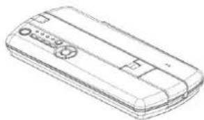
WIRELESS

VISUAL PRESENTER
CD-ROM
Image Mate
Instruction manual
natural_image
Line drawing of a mobile phone casing with buttons and ventilation slots (no text or symbols)
Manual/Image Mate CD
Contents of the CD
-Image Mate
-Instruction manual
-Basic Startup Guide

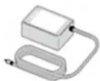
AC adapter

Power cord

USB cable



Warranty card※
Important Safeguards


※North America only
2 PART NAMES AND FUNCTIONS
Appearance
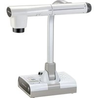
Operation of the main unit:

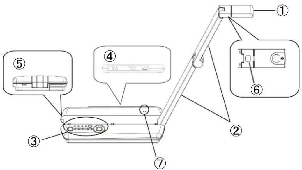
| Name | ||
| 1 | Camera head | |
| 2 | Arm | |
| 3 | Operating panel |  |
| 4 | Rear panel |  |
| 5 | Side panel |  |
| 6 | Lamp |  |
| 7 | Microphone | |
Operating panel

| Mark | Name | Function | |
| 1 |  | Power | To turn the power ON/OFF.Power ON: Blue lightPower OFF (standby status): Red light |
| 2 |  | Lamp | To turn the lamp ON/OFFNoteThe lamp is always OFF when power is turned on. |
| 3 |  | Image Rotation | To rotate the imageStill image (Captured image): Rotates by 90°Live image (Camera image): Rotates by 180° |
| 4 |  | Image Freeze / Capture | To pause the camera image by pressing this button for a short moment (less than 1 second). Press this button again to restart.To save a still image to the SD card by pressing this button for long (more than 1 second). |
| 5 |  | Menu | To show/hide the menu on the screenP27 |
| 6 |  | Image Selection | To switch the output video.LED of the selected output video 12~15 lights up.P26 |
| 7 |  | Auto Focus | To automatically focus on the object.AF works once when this button is pressed. |
| 8 |  | Zoom In | To zoom in an object. Image quality will be degraded when ZOOM-IN. Image quality will be degraded when ZOOM-IN. |
| 9 |  | Zoom Out | To zoom out an object. |
| 10 |  | Bright | To brighten the camera image. |
| 11 | [0TCX] | Dark | To darken the camera image. |
| 12 |  | Video OutputLED [Wireless] | When this button is lit in blue, a camera image is output wirelessly.Select with the Image Selection button. |
| 13 |  | Video OutputLED [USB] | When this LED is lit in blue, the product can be connected to a PC via a USB cable.Select with the Image Selection button. |
| 14 |  | Video OutputLED[HDMI] | When this button is lit in blue, external HDMI input video is output wirelessly.Select with the Image Selection button. |
| 15 |  | Video OutputLED[RGB] | When this button is lit in blue, external RGB input video is output wirelessly.Select with the Image Selection button. |
Rear panel and cable connections

| Mark Name | Function | |
| 1 | [00x0] | Security slot |
| 2 | [462k] | Plug-in for the AC adapter. Connect the supplied AC adapter. |
| 3 |  | To connect the product to a PC. (USB cable is supplied with the product.) Connect the Mini-B-Type connector to the product. |
| 4 | RGB IN | To output the video input to the [RGB IN] terminal wirelessly. |
| 5 | HDMI IN | To output the video input to the [HDMI IN] terminal wirelessly. |
① To connect a security cable.
An anti-theft security cable can be connected.
An anti-theft security cable is not supplied with the product.
② To connect the AC adapter.
Before inserting the AC adapter in an outlet, connect the DC plug of the supplied AC adapter to the [ SV ] terminal on the rear panel.
③ To connect the product to a PC with a USB cable.
Install the control software “Image Mate” contained in the supplied CD-ROM onto your PC to connect the product to a PC.
For information on the PC requirements, OS types and the software guides, see the “Image Mate” installation manual and the “HELP folder” in the CD-ROM.
④ To connect the product to a device with an analog RGB output terminal.
Connect the RGB cable to the [RGB IN] terminal on the rear panel.
Press the Image Selection button to light up the Video Output LED [RGB].
The video input to the [RGB IN] terminal is output wirelessly.
Images of the following format can be input to [RGB IN].
Supporting signals
| Resolution (dots) | Horizontal frequency (kHz) | Vertical frequency (Hz) |
| 640x480 | 31.5 | 59.9 |
| 640x480 | 37.5 | 75.0 |
| 800x600 | 37.9 | 60.3 |
| 800x600 | 46.9 | 75.0 |
| 1024x768 | 48.4 | 60.0 |
| 1024x768 | 60.0 | 75.0 |
| 1152x864 | 67.5 | 75.0 |
| 1280x768 | 47.8 | 59.9 |
| 1280x800 | 49.7 | 59.8 |
| 1280x960 | 60.0 | 60.0 |
| 1280x1024 | 64.0 | 60.0 |
| 1280x1024 | 80.0 | 75.0 |
⑤ To connect the product to a device with an HDMI output terminal.
Connect a commercially available HDMI cable to the [HDMI IN] terminal on the rear panel. The product has a Standard HDMI (Type A) terminal.
Press the Image Selection button to light up the Video Output LED [HDMI].
The video input to the [HDMI IN] terminal is output wirelessly.
Images of the following format can be input to [HDMI IN].
Supporting signals
| Resolution | Horizontal frequency (kHz) | Vertical frequency (Hz) |
| 640x480p | 31.47 | 59.94 |
| 640x480p | 31.5 | 60 |
| 720x480p | 31.47 | 59.94 |
| 720x480p | 31.5 | 60 |
| 720x576p | 31.25 | 50 |
| 1280x720p | 44.96 | 59.94 |
| 1280x720p | 45 | 60 |
| 1280x720p | 37.5 | 50 |
| 1920x1080i | 33.72 | 59.94 |
| 1920x1080i | 33.75 | 60 |
| 1920x1080i | 28.13 | 50 |
| 1920x1080p | 67.43 | 59.94 |
| 1920x1080p | 67.5 | 60 |
| 1920x1080p | 56.25 | 50 |
Note
- When using a PC with an external output mode, set the PC to the external output mode after lighting up the Video Output LED [EXT].
• We recommend using a USB 2.0 compliant USB cable.
• Operation is not guaranteed for all environments. - Press the Image Selection button to select the output video.
For the information on the switching of the output video, refer to "Switching the
output video"

- We recommend to use the AC adapter when connecting the product to a PC via a USB cable.
Side panel
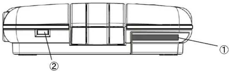
| Function | |
| 1 | To insert an SD card (commercially available).Push the card again to remove the SD card. |
| 2 | Turn on the product and the receiver and press this button for long (about 3 - 5 seconds) while the receiver is in standby mode. The product starts to establish the wireless connection with the receiver as soon as the button is released. Refer to the instruction manual for the Wireless receiver for details. |
3 PREPARATION AND CONNECTION
Setting Up

Note
- Carry the product by holding the lower part of the body in both hands. Never hold the product by the arm or the camera head.
- Pay attention to prevent the camera head from knocking against a desk or the like.
- Move the arm while supporting the body with your hand.
① Move the arm while supporting the body with your hand.

natural_image
Line drawing of a rectangular electronic device with buttons and a black arrow pointing to the side (no text or symbols)④ Move the arm in the direction indicated by an arrow.

natural_image
Diagram of a vacuum cleaner with rotating arm mechanism (no text or symbols)② Lift up the other side of the arm.

natural_image
Line drawing of a mobile phone with a scroll and control panel (no text or symbols)③ Move the camera head so that it is horizontal.

natural_image
Technical line drawing of a mechanical device with a lever and base plate (no text or symbols)CAUTION
When moving the arm, pay attention not to pinch your finger.
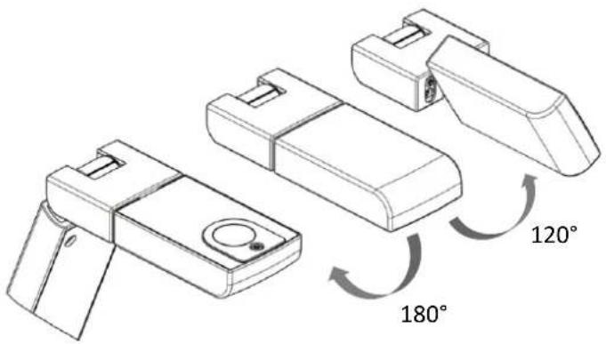
Moving Parts of the Wireless Mobile Document Camera
This unit can be moved as shown below.

Camera head
Connecting to the Wireless Receiver (Optional)

Set up the product as shown in the above drawing to start wireless communication with the Wireless receiver.
Note
For details about the configuration of the product and the Wireless receiver, refer to the instruction manual for the Wireless receiver.
Connecting to a PC

natural_image
Illustration of a laptop connected to a desk lamp via cable, with a small device attached (no text or symbols present)Set up the product as shown in the above drawing and turn on the power after connecting a PC.
Turning on the power
Power supply from the AC adapter
-
Connect the AC cord and the AC adapter. Then connect the AC adapter to the [DCINSV] terminal at the rear panel of the product, and insert the AC cord into an outlet.
-
Turn the power on by pressing the power button on the operating panel.
Power supply from the USB
Note
To operate the product with the power from the USB, a USB port that c output more than 3.5W is needed. When supplying the power from the USB, connect to the USB3.0 port of the PC or use a commercially available 2-port USB cable with power supply function to connect to the 2 USB2.0 ports of the PC.
If both are not available, use the AC adapter.(Recommendation)
-
Connect the miniUSB plug (Type B) of the supplied USB cable to the USB connector at the rear panel.
-
Connect the USB plug (Type A) of the supplied USB cable to the USB port of a PC.
-
Turn the power on by pressing the power button on the operating panel.
Note
- When connecting to the USB port, pay attention to its direction.
- When the power is supplied from the USB port (the AC adapter is not used), a video signal is not output wirelessly.
4 SHOOTING IMAGES
Adjusting the size
The display range of the document can be adjusted by pressing the [⊕ / ⊖] buttons on the operating panel.
[+] :ZOOM-IN····The object can be shown in large size.
[Q]:ZOOM-OUT···The object can be shown in small size.
Note
Zoom ratio: Digital Max. 8x
Image quality will be degraded when ZOOM-IN.
Still images and the images saved in an SD card cannot be zoomed in or out.
When the camera mode is changed while zoom function is in operation, the zoom is deactivated and the size of the image returns to normal.
Adjusting the brightness
Press the [-↑-/↓] button on the operating panel to adjust the image brightness. The brightness does not change automatically according to the brightness of the shooting environment.
[●]: bright……The image becomes bright.
[↓]: dark ·····The image becomes dark.
Adjusting the focus
Press the [AF] button to automatically focus on an object.
Turning the lamp ON/OFF
Press the [☐] button to turn on the lamp. Press the button again to turn off the lamp.
Pausing the Video
Press the [✗/☐] button for a short moment (less than 1 second) to pause the camera image. Press the button again to restart.
Note
- When a camera image is paused by pressing [ ☒/☐ ] for a short moment in digital zoom, the digital zoom is deactivated. The digital zoom is activated again when the pause is released by pressing [ ☒/☐ ] again.
- Pressing any button other than [ ☒/☐ ] button will release the pause.
Saving a still image
Press the [☐/☐] button for long (more than 1 second) to save a still image to the SD card.
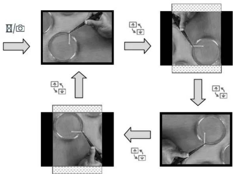
Rotating the image
• Live image (Camera image):
【Upside▲】mark in the camera head indicates the direction of the sensor.
The image appears upside-down when the camera head is set as shown in the below drawing. The image rotates by 180^ by pressing the [ ] button.

natural_image
Close-up of a white handheld device with a circular button labeled 'episde' and a plus symbol, no readable text or symbols beyond the label.- Still image (Camera image):
- The image rotates counterclockwise by 90° by pressing the [ ] button.
flowchart
graph TD
    A["Input Camera"] --> B["Camera Image"]
    B --> C{Adjust Light}
    C -->|Yes| D["Image Lensing"]
    C -->|No| E["Adjust Light"]
    D --> F["Final Camera"]
    E --> F
    style A fill:#f9f,stroke:#333
    style F fill:#bbf,stroke:#333
Note
- Both ends of the image are cut when a still image is rotated by 90^ or 270^ .
- The image that is saved in an SD card cannot be rotated.
- When a camera image is rotated, Pressing any button other than [ ] button will release the rotation.
- The image rotation cannot be used when the MENU is on display.
Switching the output video
The Video Output LED of the output terminal used is lit.
The output video can be selected by pressing the Image Selection button.
| Video Output LED | Function | |
| 1 | Wireless | To output a camera image wirelessly. |
| 2 | USB | The product can be connected to a PC via a USB cable. |
| 3 | HDMI | To output the video input to the [HDMI IN] terminal wirelessly. |
| 4 | RGB | To output the video input to the [RGB IN] terminal wirelessly. |
In the order that the output video changes (in the order that the LED lights up)
| Connected Item | 1 | Image Selection Button | 2 | Image Selection Button | 3 | Image Selection Button | ||
| AC Adaptor | Power ON | Wireless | → | HDMI | → | RGB | → | To 1 |
| USB Cable | Power ON | USB | → | No Change | ||||
| AC Adaptor USB Cable | Power ON | Wireless | → | USB HDMI | → | USB RGB | → | To 1 |
Note
- When the power is supplied from the USB port (the AC adapter is not used), a video signal is not output wirelessly.
- External input signal is not output from the USB.
5 CHANGING THE SETTINGS
Various settings for the product are changed through the menu (characters and icons) displayed on the screen.
Changing the settings
① Press the [MENU] button on the operating panel to display the menu on the screen, and then use the [ ] button to move the cursor to the icon you want to operate or set.
② Press the [AF] button to select the setting values.


flowchart
graph TD
    A["↓"] --> B["WORK"]
    B --> C["P28"]
    C --> D["WORK Screen Icon"]
    D --> E["50Hz ↓ 60Hz"]
    E --> F["P28"]
    F --> G["WORK Screen Icon"]
    G --> H["P29"]
    H --> I["WORK Screen Icon"]
    I --> J["P29"]
    J --> K["E"]
    K --> L["P29"]
    L --> M["WORK Screen Icon"]
    M --> N["P29"]
    N --> O["WORK Screen Icon"]
    O --> P["P29"]
    P --> Q["Clock Icon"]
    Q --> R["P30"]
    R --> S["Blue Box Icon"]
    S --> T["P35"]
    T --> U["Blue Box Icon"]
    U --> V["P35"]
※To go back a layer or to hide the menu, select [←] and press the [AF] button.
Descriptions of each menu
Camera output display mode menu
| Icon | Name | Selection Item | Factory Setting | Function |
 | Preferences | To display the setting menu for the camera image. | ||
 | Thumbnails | To display thumbnails of images saved in the SD card. | ||
 | Exit | To hide the menu. |

Setting menu (Second layer)
| Icon | Name | Selection Item | Factory Setting | Function |
 | Resolution※For HDMI | 1080i | √ | To set the Wireless output resolution.※1 Suitable when shooting moving objects.※2 Suitable when taking wide angle images. |
| 720p 60fps※1 | ||||
| 720p 30fps※2 | ||||
| WXGA [WXGA] | ||||
| XGA [XGA] | ||||
 | Flickerless | Off | √ | To lower the fluorescent light flickering due to power frequency. Select the same value as used for the power supply frequency. |
| 60Hz | Japan/U.S. | |||
| 50Hz | Others | |||
 | White Balance | Auto | √ | The white balance is adjusted automatically to ensure a more natural color according to the shooting scene. |
| Natural | Suitable for the scene where there is outside light. | |||
| Fluorescent | Suitable for the scene under a fluorescent light. | |||
| Incandescent | Suitable for the scene under an incandescent lamp. | |||
 | Focus | Near | Suitable for the scene under a fluorescent light. | |
| Far | ||||
| Exit | ||||
 | Edge Effect | On | To emphasize the outline of the image. | |
| Off | √ | |||
 | Language | Japanese | Japan | To set the language for the OSD menu. |
| English | Others | |||
 | Reset All | Yes | To reset the settings of resolution, flickerless, white balance, edge effect, language and brightness to factory settings. | |
| No | ||||
 | Format | Yes | To format the SD card. (No operation is allowed during the formatting process.) | |
| No | ||||
 | Clock Set | To set the time. | ||
 | Exit | To return to the camera output display mode menu. |
Note
When the output resolution is HDMI, actual output resolution might be different from the resolution set by the Setting menu depending on the connected monitor.
Setting Date/Time (Clock Set)
Press [ ] in the Setting menu (Second layer) to display the following screen. You can set the time.
Numbers displayed indicate Year (4 digits)/ Month (2 digits)/ Day (2 digits)
/ Hour (2 digits)/ :/ Minute (2 digits).
The number indicated by green arrows can be changed with the [+] / [−] buttons.
The green arrows move to the left each time when the [ -↑- ] button is pressed and move to the right each time when the [ ↓ ] button is pressed.
Press the AF button to save the set time.

Note
The clock setting will be reset automatically after a long period of non-operation. Then you will need to perform the clock setting again.
RGB External Input Signal Adjustment
When a video signal input to the [RGB IN] terminal is not displayed properly, adjustment of the phase and gain of the video signal is needed.
① Press the Image Selection button to switch to the [RGB] mode in which a video signal input to the [RGB IN] terminal is wirelessly output.
② Input a video signal to the [RGB IN] terminal to output the video wirelessly.
③ Press the [MENU] button in the operating panel for long (over 1 sec.) to display OSD menu. Perform the adjustment with buttons in the following table.
④ After the adjustment, press the [MENU] button in the operating panel for long (over 1 sec.) to clear the OSD menu.
Adjustment OSD
Upper: Phase adjustment bar (Red)
Lower: Gain adjustment bar (Blue)

Note
Adjustment cannot be performed when the OSD menu is displayed in USB Output mode. Clear the OSD menu before performing the adjustment.

natural_image
Pure gray background with a small black rectangular shape in the top-left corner (no text or symbols)●Operations in adjustment mode
| [MENU] button | To clear the OSD menu and finish the adjustment mode by pressing th button for long (over 1 sec.). |
 button button | To switch the output video and exit the adjustment mode. |
 button button | To adjust the phase of the output video signal. (Adjustment range: 0~31)The Phase adjustment bar (Red) in the OSD menu moves. |
 button button | To adjust the phase of the output video signal. (Adjustment range: 0~31)The Phase adjustment bar (Red) in the OSD menu moves. |
 button button | To increase the gain of the output video signal. (Adjustment range: 0~64)The Gain adjustment bar (Blue) in the OSD menu moves. |
 button button | To decrease the gain of the output video signal. (Adjustment range: 0~64)The Gain adjustment bar (Blue) in the OSD menu moves. |
 [↓] buttons(simultaneous pressing) [↓] buttons(simultaneous pressing) | To return the adjusted values (phase and gain) to factory settings. |
 buttons buttons | This button is not used in this adjustment. |
 buttons buttons | This button is not used in this adjustment. |
 buttons buttons | This button is not used in this adjustment. |
 buttons buttons | This button is not used in this adjustment. |
6 CONNECTING TO A PC
Installing the software
Install the control software “Image Mate” contained in the supplied CD-ROM onto your PC to connect the product to a PC.
For details about the operating environment and the OS of the connected computer or the operation of the software, refer to the installation manual of Image Mate.
Connecting to a PC

natural_image
Diagram showing connections between a projector, laptop, and lamp (no text or symbols present)Set up the product as shown in the above drawing and turn on the power after connecting a PC.
Note
- When the product does not recognize the PC, turn off the product and turn it on again.
- Depending on the environment of your PC, the product is not recognized when the PC is in standby status or in sleep status. Make sure to cancel the standby
Controlling the product from a USB-connected PC
By using the “Image Mate”, you can perform the following tasks:
- To transfer the camera image to a PC
- To operate the product from a PC
CAUTION
- Do not connect/disconnect the USB cable while operating the operating panel.
• We recommend using a USB 2.0-compliant USB cable.
- Use a high specification PC (Core2Duo or higher) or down-convert the resolution to 640x480.
- When viewing an image with other viewer than Image Mate, start the viewer after setting the unit to USB mode.
7 USING AN SD CARD
With this product, you can save the camera image as a picture on an SD card. You can also display the data stored in the SD card on the screen.
Before you begin, insert a commercially available SD card into the SD card slot of the side panel.

natural_image
Line drawing of a handheld device with an inset showing a device being inserted (no text or symbols present)Note
· SD card
- The SDXC card cannot be used.
- Formatting the SD card with the product before you use is recommended.
· Using the SD card class 6 or higher is recommended.
- It may take some time to recognize the SD card after inserting it or to save images to the SD card.
- Do not remove the SD card when it is in read/write operation.
• We do not guarantee the proper operation when you use the image taken by this product with any third party product or when you use the image taken by any third party product with this product or when you use the modified image with the product.
Saving images
① Press the [☐/☐] button on the operating panel for 1 second or more while the menu is not displayed on the screen.
② Saving begins when [ ] appears on the screen.
Displaying the saved data
① Press the [MENU] button on the operating panel to display the menu.
② Select [ ] and press the [ AF] button on the operating panel to display thumbnails (list of pictures).
③ Move the cursor using the [ -+]·[ ↓ ]·[ +]·[ -] button on the operating panel.
④ Press the [AF] button to display the selected picture full-screen.

Note
- Files larger than 5MB cannot be displayed.
- We do not guarantee the proper operation when you use the image taken by this product with any third party product or when you use the image taken by any third party product with this product or when you use the modified image with this product.
- Images with more than 4000 horizontal pixels or 3000 vertical pixels cannot be displayed.
Thumbnail display mode
Thumbnail display mode menu
| Icon | Name | Selection Item | Factory Setting | Function |
 | Camera | To display the camera image. |
Still image display mode menu
| Icon | Name | Selection Item | Factory Setting | Function |
 | Camera | To display the camera image. | ||
 | Delete | Yes | To delete the displayed still image. Next image is displayed after the deletion. | |
| No | ||||
 | Exit | To hide the menu. |
8 TROUBLE SHOOTING
If you have a problem or questions about this product, please read this troubleshooting guide first. If the problem still exists, consult the dealer from whom you purchased this product.
| Symptom | Possible cause/ remedy |
| No image is displayed. | The cable is not properly connected.The AC adapter is disconnected from the wall outlet.The AC adapter is disconnected from the power supply socket of the unit.The power is not ON. (Blue light)Zoom is set at the TELE side, displaying only the white/black part of the document.If you turn the power ON immediately after turning it OFF, the unit may not start. Wait for several seconds after turning the power OFF, and then turn it back ON.The setting of the Image Selection does not correspond to the video cable connected.Reconnect the AC adapter.When the power is supplied from USB, check if the USB cable is connected properly.Is the initial setting of the product and the receiver performed?Install the product and the receiver within the range where an electric wave reaches (max.10m or so). When there is reinforcing steel, metal or concrete between the product and the receiver, the wireless communication can not be established.Are the product and the receiver installed inside?This product uses electric waves in the 5GHz band. It may receive interference from other wireless equipments, making the product difficult to transmit video signals. |
| The output image (resolution) changes automatically. | When the HDMI monitor is connected, the output image (resolution) is automatically changed based on information from the connected monitor |
| No image is displayed from the USB. | The slide switch is not set to the correct image output (USB). Set the switch correctly. |
| The image is out of focus. | · The document (object) is too close to the lens. Move the document (object) slightly away from the lens.· Auto focus may have difficulty in adjusting correctly. Adjust the focus manually by using "FOCUS" in the setting menu. |
| The image is too dark. | The intensity of the lighting is insufficient. Press the [💡] button on the operating panel to adjust the brightness. Turn on the lamp. |
| The image is striped. | · This may be interference fringes between dots of the printed material and TV scanning lines or CMOS pixels. Changing the shooting range may help the problem.· Vertical stripes may appear on an LCD projector imag Manually adjusting the dot clock at the projector side may help the problem. |
| There is a flickering of the fluorescent light. | · Set the value of the flicker correction in the menu same as the power frequency of your area. |
| Images on the SD card are not displayed. | · Remove the SD card, wait a few seconds and reinsert. |
| The image does not move. | · Camera image is set to [Pause]. Press the Pause button on the operating panel again to restart. |
| After inserting the SD card, operations cannot be performed. | · The SD card is not being read correctly. Format the card using the main unit. |
| The set time is reset. | · The clock setting will be reset automatically after a long period of non-operation. Then you will need to perform the clock setting again. After the clock setting is performed, connect the AC adapter and leave the product for over 6 hours to charge the battery for the clock. |
About the lamp (LED lamp)
The brightness of the lamp will diminish with long-term use. If its brightness has significantly diminished, consult the dealer from whom you purchased the product or our nearest branch/office for replacement.
About long-term usage of this product
Due to the lifetime of its parts, if the product is used for longer than the warranty period, its performance and quality may deteriorate. In this case, we will replace the parts for a charge. Consult the dealer from whom you purchased the product or our nearest branch/office.
9 SPECIFICATIONS
General
| Item | Specifications |
| Power source | DC5V(AC adapter AC100~240V)PC requirements for the power supply from a USB:- A PC with the USB3.0 port- A PC with 2 USB portsRefer to P22 for details about the connection procedure. |
| Power consumption | 7.4W(USB Power Supply:3.5W) |
| Outside dimensions | W101×D416×H338[mm] (When setup)W101×D 行 226×H28[mm] (When folded) |
| Weight | Approx. 590g |
| Input terminal | RGB input Mini Dsub 15P connector female×1HDMI input Type A Standard HDMI terminal |
| USB interface | USB2.0 High Speed、Full Speed compliantUSB VIDEO CLASS Ver.1.1compliantType Mini B receptacle ×1 |
| Memory interface | SD card slot×1 |
Main Camera
| Item | Specifications | |||||
| Lens | F2.9 | |||||
| Frame rate / Shooting area | Frame rate | Max. | Min. | |||
| 1080i | 30fps | 342mm | 192mm | 42.75mm | 24mm | |
| 1080p | 15fps/3.75fps | 342mm | 192mm | 42.75mm | 24mm | |
| 720p | 60fps | 214mm | 120mm | 26.75mm | 15mm | |
| 720p | 30fps/*7.5fps | 342mm | 192mm | 42.75mm | 24mm | |
| WXGA | 20fps/*5fps | 342mm | 214mm | 42.75mm | 26.75mm | |
| XGA | 20fps/*5fps | 342mm | 257mm | 42.75mm | 32.125mm | |
| VGA | 20fps/5fps | 342mm | 257mm | 42.75mm | 32.125mm | |
| * Does not support Wireless output. | ||||||
Main Camera
| Item | Specifications |
| Limit of focus adjustment | From lens surface 70mm~∞ |
| Focus | Auto/ Manual |
| Image pick-up element | 1/3.2" CMOS Sensor |
| Effective pixels | Horizontal 2048, Vertical 1536 |
| Sync. system | Internal |
| Wireless Output | Camera Image Output1080i, 720p 60fps, 720p 30fpsWXGA:1280x800(60Hz), XGA:1024x768(60Hz)External Input Image Output(HDMI and Analog RGB)640x480(60Hz/75Hz), 800x600(60Hz/75Hz)1024x768(60Hz/75Hz), 1280x768(60Hz)1280x800(60Hz), 1280x1024(60Hz/75Hz)1152x864 (60Hz), 1280x960(60Hz)480p, 576i, 576p, 720p, 1080i, 1080p |
| USB output | Camera Image output1080p, 720p(max Shooting area: 342mmx192mm)WXGA:1280x800, XGA:1024x768, VGA:680x480 |
| White balance | Auto/ Outdoor/ Fluorescent light/ Incandescent lamp |
| Brightness control | Provided |
| Image rotation | Camera live image :0°/180°Camera Still image :0°/90°/180°/270° |
| Edge effect | ON/ OFF |
| Pause | Provided |
| Still image capture | Provided |
| Flicker correction | OFF / 60Hz / 50Hz |
Illumination Device
| Item | Specifications |
| Illumination | White LED |
Trademarks and License
ELMO and Image Mate are registered trademarks of ELMO Co., Ltd.
SD、SDHC、SD (SD logo) and SD (SDHC logo) are trademarks of SD-3C, LLC.
HDMI, Hgo in High-Definition Multimedia interface are trademarks or registered trademarks of HDMI Licensing LLC.
All other company/ product names described in this manual are trademarks or registered trademarks of their respective companies.
WARNING
Unauthorized recording of copyrighted slide films, materials, photographs, etc. may infringe on the rights of copyright owners and be contrary to copyright laws.
Repairable Period
ELMO will maintain and keep spare parts for this product for eight years after the discontinuation of this product. After this period, ELMO will no longer offer repair service for this product.
ELMO CO., LTD.
6-14, Meizen-cho, Mizuho-ku, Nagoya, 467-8567, Japan
OVERSEAS SUBSIDIARY COMPANIES
ELMO USA CORP.
Headquarters 1478 Old Country Road
Plainview, NY 11803-5034, U.S.A
Tel:(516) 501-1400 Fax:(516) 501-0429
E-mail: elmo@elmousa.com Web: http://www.elmousa.com
West Coast Branch Cypress Pointe Business Park
5676 Corporate Avenue
Cypress, CA 90630, U.S.A
Tel:(714) 828-8457 Fax:(714) 828-8429
Please read this instruction manual carefully before using this product and keep it for future reference.
IMPORTANT SAFEGUARDS
■ Read Instructions
All the safety and operating instructions should be read before the product is operated.
■ Retain Instructions
The safety and operating instructions should be retained for future reference.
■ Heed Warnings
All warnings on the product and in the operating instructions should be adhered to.
■ Follow Instructions
All operating and use instructions should be followed.
■ Cleaning
Unplug this product from the wall outlet before cleaning. Do not use liquid cleaners or aerosol cleaners. Use a damp cloth for cleaning.
■ Attachments
Do not use attachments not recommended by the product manufacturer as they may cause hazards.
■ Water and Moisture
Do not use this product near water - for example, near a bath tub, wash bowl, kitchen sink, or laundry tub, in a wet basement, or near a swimming pool, and the like.
■ Placement
Do not place this product on an unstable cart, stand, tripod, bracket, or table. The product may fall, causing serious injury to a child or adult, and serious damage to the product. Use only with a cart, stand, tripod, bracket, or table recommended by the manufacturer, or sold with the product.
Any mounting of the product should follow the manufacturer's instructions, and should use a mounting accessory recommended by the manufacturer.
■ Ventilation
Slots and openings in the cabinet are provided for ventilation and to ensure reliable operation of the product and to protect it from overheating, and these openings must not be blocked or covered. The openings should never be blocked by placing the product on a bed, sofa, rug, or other similar surface. This product should not be placed in a built-in installation such as a bookcase or rack unless proper ventilation is provided or the manufacturer's instructions have been adhered to.
■ Power Sources
This product should be operated only from the type of power source indicated on the marking label. If you are not sure of the type of power supply to your home consult your appliance dealer or local power company. For products intended to operate from battery power, or other sources, refer to the operating instructions.
■ Grounding or Polarization
This product may be equipped with either a polarized 2-wire AC line plug (a plug having one blade wider than the other) or a 3-wire grounding type plug, a plug having a third (grounding) pin. The 2-wire polarized plug will fit into the power outlet only one way. This is a safety feature. If you are unable to insert the plug fully into the outlet, try reversing the plug. If the plug still fails to fit, contact your electrician to replace your obsolete outlet. Do not defeat the safety purpose of the polarized plug. The 3-wire grounding type plug will fit into a grounding type power outlet. This is a safety feature. If you are unable to insert the plug into the outlet, contact your electrician to replace your obsolete outlet. Do not defeat the safety purpose of the grounding type plug.
■ Power-Cord Protection
Power-supply cords should be routed so that they are not likely to be walked on or pinched by items placed upon or against them, paying particular attention to cords at plugs, convenience receptacles, and the point where they exit from the product.
■ Lightning
For added protection for this product during a lightning storm, or when it is left unattended and unused for long periods of time, unplug it from the wall outlet and disconnect the antenna or cable system. This will prevent damage to the product due to lightning and power-line surges.
■ Overloading
Do not overload wall outlets, extension cords, or integral convenience receptacles as this can result in a risk of fire or electric shock.
■ A product and cart combination should be moved with care.
Quick stops, excessive force, and uneven surfaces may cause the product and cart combination to overturn.
■ Object and Liquid Entry
Never push objects of any kind into this product through openings as they may touch dangerous voltage points or short-out parts that could result in a fire or electric shock. Never spill liquid of any kind on the product.
■ Servicing
Do not attempt to service this product yourself as opening or removing covers may expose you to dangerous voltage or other hazards. Refer all servicing to qualified service personnel.
■ Damage Requiring Service
Unplug this product from the wall outlet and refer servicing to qualified service personnel under the following conditions:
-When the power-supply cord or plug is damaged.
-If liquid has been spilled, or objects have fallen into the product.
-If the product has been exposed to rain or water.
-If the product does not operate normally by following the operating instructions. Adjust only those controls that are covered by the operating instructions as an improper adjustment of other controls may result in damage and will often require extensive work by a qualified technician to restore the product to its normal operation.
-If the product has been dropped or damaged in any way.
-When the product exhibits a distinct change in performance - this indicates a need for service.
■ Replacement Parts
When replacement parts are required, be sure the service technician has used replacement parts specified by the manufacturer or have the same characteristics as the original part. Unauthorized substitutions may result in fire, electric shock or other hazards.
■ Safety Check
Upon completion of any service or repairs to this product, ask the service technician to perform safety checks to determine that the product is in proper operating condition.
■ Heat
The product should be situated away from heat sources such as radiators, heat registers, stoves, or other products (including amplifiers) that produce heat.


SA 1965
The lightning flash with arrowhead symbol, within an equilateral triangle, is intended to alert the user to the presence of uninsulated "dangerous voltage" within the product's enclosure that may be of sufficient magnitude to constitute a risk of electric shock to persons. This marking is located at the bottom of product.

SA 1966
The exclamation point within an equilateral triangle is intended to alert the user to the presence of important operating and maintenance (servicing) instructions in the literature accompanying the product.
WARNING:
TO REDUCE THE RISK OF FIRE OR ELECTRIC SHOCK, DO NOT EXPOSE THIS PRODUCT TO RAIN OR MOISTURE.
FCC CAUTION:
Changes or modifications not expressly approved by the party responsible for compliance could void the user's authority to operate the product.
■ FCC & IC statement ■
IMPORTANT NOTE:
This Class B digital product complies with Canadian ICES-003.
This product complies with Part 15 of FCC Rules and Industry Canada licence-exempt RSS standard(s). Operation is subject to the following two conditions: (1) this product may not cause interference, and (2) this product must accept any interference, including interference that may cause undesired operation of this product.
This product has been tested and found to comply with the limits for a Class B digital device, pursuant to part 15 of the FCC Rules. These limits are designed to provide reasonable protection against harmful interference in a residential installation.
This product generates, uses and can radiate radio frequency energy and, if not installed and used in accordance with the instructions, may cause harmful interference to radio communications.
However, there is no guarantee that interference will not occur in a particular installation.
If this product does cause harmful interference to radio or television reception, which can be determined by turning the product off and on, the user is encouraged to try to correct the interference by one or more of the following measures:
-Reorient or relocate the receiving antenna.
-Increase the separation between the equipment and receiver.
-Connect the equipment into an outlet on a circuit different from that to which the receiver is connected.
-Consult the dealer or an experienced radio/TV technician for help.
When using IEEE 802.11a wireless LAN, this product is restricted to indoor use, due to its operation in the 5.15 to 5.25GHz frequency range.
The FCC requires this product to be used indoors for the frequency range of 5.15GHz to 5.25GHz to reduce the potential for harmful interference to cochannel mobile satellite systems.
High-power radar is allocated as the primary user of the 5.25 to 5.35GHz and 5.65 to 5.85GHz bands.
These radar stations can cause interference with and/or damage to this product.
In some environments, the use of wireless devices may be restricted.
Such restrictions may apply in hospitals, near explosives, in hazardous locations, and so on.
If you are uncertain of the policy that applies to the use of this product, ask for authorization to use it before you turn it on.
FCC Radiation Exposure Statement:
This product complies with FCC radiation exposure limits set forth for an uncontrolled environment. This product should be installed and operated with minimum distance 20cm between the radiator & your body.
This transmitter must not be co-located or operating in conjunction with any other antenna or transmitter.
The availability of some specific channels and/or operational frequency bands are country dependent and are firmware programmed at the factory to match the intended destination. The firmware setting is not accessible by the end user.
Radiation Exposure Statement:
This product complies with Canada radiation exposure limits set forth for an uncontrolled environment. This product should be installed and operated with minimum distance 20cm between the radiator & your body.
- Do not use this product outside your Country.
- Depending on the specification of the HDMI device, this product may not work properly or there may be some effect on performance with this product.
- Compatibilities with supporting models were confirmed in our environment.
We do not guarantee operation in all environments.
- Depending on the devices to be used with this product, CEC function may not be used.
- Because wireless connection takes a time in the low temperature environment, please use after switching it on and waiting for a while..
- Product design and the specification are subject to change without prior notice.
- and are trademark of ELMO Co., Ltd.
- All other company/products names described in this manual are trademarks or registered trademarks of respective companies.
SUPPLIED ITEMS
Contact your dealer if any of the following items are not included in the package.
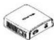
VP Receiver

AC adapter (USA)
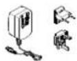
AC adapter with attachments (Europe / England)

Instruction Manual

- Supplied AC attachment is for your country.
- When using the product, attach the AC attachment to the AC adapter.
Assembling/ Disassembling procedure for the AC adapter
Assemble or disassemble the AC adapter and the AC attachment by taking the following procedure.
Make sure to unplug the cable before starting the assembling/disassembling work.
■ Assembling
Slide the AC attachment along the groove of the AC adapter and press it into until you hear a "click" sound.
■ Disassembling
While pressing the center of the AC attachment, slide the AC attachment to remove.
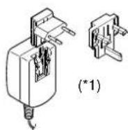


*1 Use an appropriate AC attachment for your region.
■Power light (White)
- Lit : Power is ON.
- Off: Power is OFF.
- Blink : Sleep mode.

Caution
- Please remove the protection sheet of the VP Receiver before you use.
- The Micro USB terminal of the VP Receiver is for power supply only and other USB devices cannot be connected. Use the supplied AC adapter to supply power to the VP Receiver. Do not use the bus powered USB to supply power to the VP Receiver. The power consumption of the VP Receiver is higher than the standard of the USB bus power.
- Use the Visual transmitter that supports WHDI standard.
- HDMI output of this product complies with HDMI standard.
- Because wireless connection takes a time in the low temperature environment, please use after switching it


on and waiting for a while.
Connecting the VP Receiver
Connect the equipments as shown in the drawing.

flowchart
graph TD
    A["Monitor (*2)"] --> B["HDMI Connector"]
    B --> C["Projector (*2)"]
    C --> D["HDMI cable (*3)"]
    D --> E["VP Receiver"]
    E --> F["AC adapter (*1)"]
    F --> G["Visual transmitter"]
    G --> H["USB power"]
    E --> I["HDMI out"]
    style A fill:#f9f,stroke:#333
    style B fill:#ccf,stroke:#333
    style C fill:#cfc,stroke:#333
    style D fill:#fcc,stroke:#333
    style E fill:#cff,stroke:#333
    style F fill:#ffc,stroke:#333
    style G fill:#fcc,stroke:#333
    style H fill:#ffc,stroke:#333

*1 AC adapter is different according to the destination.
*2 Change the input mode of the image output device to HDMI.
*3 Use a commercially available HDMI cable (Type A).
Performing the wireless settings
Perform the wireless settings before using the VP Receiver.
Connect the Visual transmitter that supports HDMI before performing the wireless settings.
Display the menu by pressing the Menu/Select button. Select "Setup", then press the Menu/Select button again.
You can add/remove or modify the name of the Visual transmitter from the menu.
■Add the Visual transmitter
- Select "Setup". Then press the Menu/Select button.
- Select "Add new Video Source" from the menu. Then press the Menu/Select button.
- The VP Receiver is now ready to receive signals from the Visual transmitter. Perform the registration from the Visual transmitter.
- The VP Receiver registers the Visual transmitter once the signal from the Visual transmitter is received by the VP Receiver.
- Select "OK" and press the Menu/Select button. Then exit the menu.

- For details about the operation of the Visual transmitter, refer to the instruction manual of the respective Visual transmitter.
■Remove the Visual transmitter
- Select "Setup". Then press the Menu/Select button.
- Select "Remove Video Source" from the menu. Then press the Menu/Select button.
- Select the Visual transmitter to remove. Then exit the menu.
- Select "OK" and press the Menu/Select button. Then exit the menu.
■Modify the name of the Visual transmitter
- Select "Setup". Then press the Menu/Select button.
- Select "Modify Video Source Name" from the menu. Then press the Menu/Select button.
- Select the registered Visual transmitter. Then press the Menu/Select button.
- A cursor is displayed. Select the part you want to modify. Then press the Menu/Select button.
- Select a letter once the color of the cursor changes.
- Press the Menu/Select button after selecting a letter to input.
- Press the Menu/Select button for long after all the letters has been input. Select "Save" to finish.
Selecting the Video Source
Display the menu by pressing the Menu/Select button.
A list of registered Visual Transmitters appears in the menu. Select the desired Visual Transmitter.
Press the Menu/Select button to output the image of the selected Visual Transmitter.
When the message of "Please remove and register this OOO again" is shown at linking with the transmitter, please remove and add the transmitter again.
SLEEP MODE
The VP Receiver enters Sleep mode in 3 minutes after the wireless connection with the Visual transmitter is disconnected.
To return to normal operation mode, press one of either the Menu/Select button, the Down button or the Up button of the VP Receiver after power on the Visual transmitter.
The image appears once the wireless connection with the Visual transmitter is established.
To open the menu while "Linking" image is in display, press the Menu/Select button for long.
Perform the wireless settings after the menu is displayed.
TROUBLESHOOTING
If trouble occurs or you have any queries, first check this section.
If the problem persists, check your warranty and contact the dealer where you purchased the product.
| The VP Receiver does not work. | The AC adapter is disconnected. Check the connection between the AC adapter and the wall outlet. |
| Is the Visual transmitter registered?Add the Visual transmitter. | |
| The VP Receiver is in Sleep mode.Cancel the Sleep mode according to the instruction described in “SLEEP MODE”. | |
| The equipment which uses the same frequency may cause radio interference.Check the surrounding radio frequency environment. | |
| The AC adapter is disconnected from the VP Receiver.Check the connection between the AC adapter and the VP Receiver. | |
| No image is displayed.orThe image is distorted. | HDMI cable is not connected properly.Firmly insert HDMI cable into the connector. |
| The cable is damaged.Do not use a damaged cable. | |
| The input signal is out of the display range of the Visual transmitter.Check the resolution. | |
| The equipment which uses the same frequency may cause radio interference.Check the surrounding radio frequency environment. | |
| No sound is output. | HDMI cable is not connected properly.Firmly insert HDMI cable into the connector. |
| The cable is damaged.Do not use a damaged cable. | |
| No audio from the Visual transmitter is input.No sound is output when there is no audio input. | |
| The volume of the Visual transmitter or the image output device is set to minimum.Turn up the volume. |

Caution
- When error message appears, follow the instruction to fix the error.
- If the problem persists, the product may be defective. Contact the dealer where you purchased the product for repair.
PRODUCT SPECIFICATIONS
| Operating Temperature | 0°C - 40°C (32° F – 104° F) |
| Wireless Band Used | 5190MHz - 5795MHz (USA / Canada)5190MHz - 5670MHz (Europe / Eurasia) |
| Communication Distance | Approx. 10m (32.8feet)(differs depending on the usage conditions) |
| Power Supply | AC adapterInput: 100V-240V, 50/60Hz(0.5A:USA/JAPAN, 0.3A:Others)Output: 5V, 2A |
| Standards | HDMI / WHDI standard compliance, including HDCP |
| Transmitter registration | 8 sets |
| HDMI OUT (Type A) | Image output:VGA (640x480)60Hz/75Hz, SVGA (800x600)60Hz/75Hz, XGA (1024x768) 60Hz/75Hz,WXGA (1280x768) 60Hz, WXGA (1280x800) 60Hz, SXGA (1280x1024) 60Hz/75Hz1152x864 (60Hz), 1280x960(60Hz) 480p, 576p, 720p, 1080i, 1080p |
| Audio output: 192 kHz x 24 bit | |
| Power Consumption (Current) | 5.5W( 5V / 1.1A) without AC adapter (USA / Canada)7W( 5V / 1.4A) without AC adapter (Europe / Eurasia) |
| External Dimensions | L83 x W80 x H31 (mm)L3 1/4" x W3 1/8" x H1 1/4" |
| Weight | 110g (0.24lb) |
ELMO CO., LTD. 6-14, Meizen-cho, Mizuho-ku, Nagoya, 467-8567, Japan
ELMO USA CORP.
Headquarters 1478 Old Country Road, Plainview, NY 11803-5034, U.S.A
Tel:(516) 501-1400 Fax:(516) 501-0429
E-mail: elmo@elmousa.com Web: http://www.elmousa.com
West Coast Branch Cypress Pointe Business Park, 5676 Corporate Avenue
Cypress, CA 90630, U.S.A
Tel:(714) 828-8457 Fax:(714) 828-8429
ELMO Europe SAS


- ■ Retain Instructions
- ■ Heed Warnings
- ■ Follow Instructions
- ■ Cleaning
- ■ Attachments
- ■ Water and Moisture
- Placement
- Ventilation
- Power Sources
- ■ Grounding or Polarization
- ■ Power-Cord Protection
- Lightning
- ■ Overloading
- ■ Object and Liquid Entry
- Servicing
- ■ Damage Requiring Service
- ■ Replacement Parts
- ■ Safety Check
- Heat
- WARNING:
- TO REDUCE THE RISK OF FIRE OR ELECTRIC SHOCK, DO NOT EXPOSE THIS PRODUCT TO RAIN OR MOISTURE.
- FOR UNITED STATES USERS:
- INFORMATION
- USER-INSTALLER
- CAUTION:
- Wash hands after handling.
- BEFORE YOU USE
- Note
- CONTENTS
- TROUBLE SHOOTING....37
- SPECIFICATIONS....39
- BUNDLED ITEMS
- PART NAMES AND FUNCTIONS
- Appearance
- Rear panel and cable connections
- Side panel
- PREPARATION AND CONNECTION
- Setting Up
- CAUTION
- Moving Parts of the Wireless Mobile Document Camera
- Connecting to the Wireless Receiver (Optional)
- Connecting to a PC
- Turning on the power
- Power supply from the AC adapter
- Power supply from the USB
- SHOOTING IMAGES
- Adjusting the size
- Adjusting the brightness
- Adjusting the focus
- Turning the lamp ON/OFF
- Pausing the Video
- Saving a still image
- Rotating the image
- Switching the output video
- CHANGING THE SETTINGS
- Changing the settings
- Descriptions of each menu
- Setting Date/Time (Clock Set)
- RGB External Input Signal Adjustment
- CONNECTING TO A PC
- Installing the software
- Controlling the product from a USB-connected PC
- USING AN SD CARD
- Saving images
- Displaying the saved data
- Thumbnail display mode
- TROUBLE SHOOTING
- About the lamp (LED lamp)
- About long-term usage of this product
- SPECIFICATIONS
- Trademarks and License
- WARNING
- Repairable Period
- ELMO CO., LTD.
- OVERSEAS SUBSIDIARY COMPANIES
- IMPORTANT SAFEGUARDS
- ■ Lightning
- ■ A product and cart combination should be moved with care.
- ■ Servicing
- ■ Heat
- FCC CAUTION:
- ■ FCC & IC statement ■
- SUPPLIED ITEMS
- Assembling/ Disassembling procedure for the AC adapter
- Connecting the VP Receiver
- Performing the wireless settings
- Selecting the Video Source
- SLEEP MODE
- TROUBLESHOOTING
- PRODUCT SPECIFICATIONS
Brand : Elmo
Model : MO-1w
Category : Camera