
RHGCH902B-M - Range hood RUSSELL HOBBS - Free user manual and instructions
Find the device manual for free RHGCH902B-M RUSSELL HOBBS in PDF.


| Product Type | Range Hood |
| Brand | Russell Hobbs |
| Model | RHGCH902B-M |
| Width | 90 cm |
| Installation Type | Wall-mounted chimney hood |
| Extraction Type | Ducted or recirculating (with charcoal filter) |
| Motor Type | Single motor |
| Number of Fan Speeds | 3 speeds |
| Maximum Extraction Rate | Approximately 650 m³/h |
| Noise Level | Approximately 65 dB max |
| Lighting | LED lights (2 x 1.5 W) |
| Control Type | Electronic push buttons |
| Filter Type | Aluminum grease filter (washable) |
| Charcoal Filter | Optional accessory for recirculation mode |
| Duct Diameter | 150 mm |
| Power Supply | 220-240 V ~ 50 Hz |
| Rated Power | Approximately 200 W |
| Energy Class | B |
| Dimensions (H x W x D) | Approx. 60-110 x 90 x 50 cm |
| Net Weight | Approximately 15 kg |
| Included Accessories | Grease filter, user manual, mounting kit |
| Maintenance | Grease filter washable monthly; charcoal filter replace every 3-6 months |
| Safety Features | Overheat protection, auto shut-off (if applicable) |
| Warranty | 2 years (standard) |
Frequently Asked Questions - RHGCH902B-M RUSSELL HOBBS
User questions about RHGCH902B-M RUSSELL HOBBS
0 question about this device. Answer the ones you know or ask your own.
Ask a new question about this device
Download the instructions for your Range hood in PDF format for free! Find your manual RHGCH902B-M - RUSSELL HOBBS and take your electronic device back in hand. On this page are published all the documents necessary for the use of your device. RHGCH902B-M by RUSSELL HOBBS.
USER MANUAL RHGCH902B-M RUSSELL HOBBS
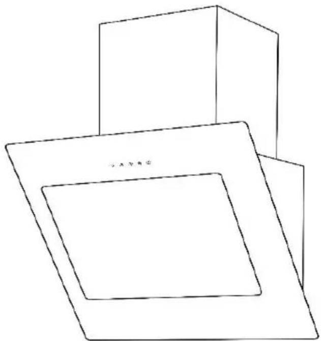
Cooker Hood
Instruction Manual
natural_image
Simple line drawing of three overlapping 3D rectangular blocks with no text or symbolsModelnumber(s):
RHGCH902B-M
For Customer Services & Spare Parts please call 0345 208 8750
or visit us at mda.russellhobbs.com
IMPORTANT:
RETAIN FOR FUTURE REFERENCE
Contents
Safety Instructions 3-6
Product Overview 7
Positioning 8
Operating modes 9
Installation 10-15
Usage 16
Cleaning and Maintenance 17-23
Aluminium & carbon grease filters 19-21
Replacing the light module(s) 22-23
Trouble shooting 24
Connection to the mains supply 25
Guarantee 26
Technical specification 27
Safety Instructions
Important note:
Please read this booklet before installing and switching on this appliance. The manufacturer assumes no responsibility for incorrect installation and usage as described in this booklet.
This appliance can be used by children aged from 8 years and above and persons with reduced physical, sensory or mental capabilities or lack of experience and knowledge if they have been given supervision or instruction concerning use of the appliance in a safe way and understand the hazards involved. Children shall not play with the appliance.
- Children should be supervised to ensure that they do not play with the appliance.
- Children must not clean the appliance or carry out general maintenance unless they are at least 8 years old and are being supervised.
- Keep children below the age of 8 years old at a safe distance from the appliance and power cable.
- If the supply lead is damaged it must be replaced by a qualified person using the correct lead, available from 0345 208 8750.
- The appliance can only be used safely if it is correctly installed according to the safety instructions. The installer is responsible for ensuring that the appliance works correctly after installation.
- This appliance is intended for domestic use and the household environment only. The appliance is not intended for use outside.
- Do not leave the appliance unattended during operation. The manufacturer is not liable for damage which is caused by improper use or incorrect operation.
- Check the appliance for damage after unpacking it. Do not connect the appliance if it has been damaged in transport.
- This appliance is not intended for operation with an external clock timer or a remote control.
Safety Instructions
- Packaging material is dangerous to children. Never allow children to play with packaging material.
- Risk of Death - Always ensure adequate fresh air in the room if the appliance is being operated in extraction-air mode at the same time as room air-dependent heat-producing appliance(s) are being operated.
- Room air-dependent heat-producing appliances (e.g. gas, oil, wood or coal operated heaters, continuous flow heaters or water heaters) obtain combustion air from the room in which they are installed and discharge the exhaust gases into the open air through an exhaust gas system (e.g. a chimney).
- In combination with an activated vapour extractor hood, room air is extracted from the kitchen and neighbouring rooms – a partial vacuum is produced if not enough fresh air is supplied. Toxic gases from the chimney or the extraction shaft are sucked back into the living space.
- Adequate incoming air must therefore always be ensured.
- An incoming/exhaust air wall box alone will not ensure compliance with the limit.
- Safe operation is possible only when the partial vacuum in the place where the heat producing appliance is installed does not exceed 4 Pa (0.04 mbar). This can be achieved when the air needed for combustion is able to enter through openings that cannot be sealed, for example in doors, windows, incoming/ exhaust air wall boxes or by other technical means.
- In any case, consult your responsible Master Chimney Sweep. They will be able to assess the house's entire ventilation setup and will suggest the suitable ventilation measures to you.
Safety Instructions
- Risk of Fire - Grease deposits in the grease filter may catch fire. Clean the grease filter at least every 2 months.
- Never operate the appliance without the grease filter.
- Grease deposits in the grease filter may catch fire. Never work with naked flames close to the appliance (e.g. flambéing). Do not install the appliance near a heat producing appliance for solid fuel (e.g. wood or coal) unless a closed, non-removable cover is available. There must be no flying sparks.
- Hot oil and fat can ignite very quickly. Never leave hot fat or oil unattended. Never use water to put out burning oil or fat. Switch off the hotplate. Extinguish flames carefully using a lid, fire blanket or something similar.
- When gas burners are in operation without any cookware placed on them, they can build up a lot of heat. A ventilation appliance installed above the cooker may become damaged or catch fire. Only operate the gas burners with cookware on them.
- Operating several gas burners at the same time gives rise to a great deal of heat. A ventilation appliance installed above the cooker may become damaged or catch fire. Never operate two gas burners simultaneously on the highest flame for longer than 15 minutes. One large burner of more than 5 kW (wok) is equivalent to the power of two gas burners.
- The accessible parts become very hot when in operation. Never touch hot parts. Keep children at a safe distance.
- Components inside the appliance may have sharp edges. Wear protective gloves.
- Items placed on the appliance may fall down. Do not place any objects on the appliance.
Safety Instructions
- A defective appliance may cause electric shock. Never switch on a defective appliance. Unplug the appliance from the mains or switch off the circuit breaker in the fuse box. Contact the after-sales service.
- Incorrect repairs are dangerous. Repairs may only be carried out and damaged power cables replaced by one of our trained after-sales technicians. If the appliance is defective, unplug the appliance from the mains or switch off the circuit breaker in the fuse box. Contact the after-sales service.
- Do not use any high-pressure cleaners or steam cleaners, which can result in an electric shock.
- Always switch on the appliance while cooking to avoid condensation. Condensation can produce corrosion damage.
• Always replace faulty bulbs to prevent the remaining bulbs from overloading. - Risk of damage due to ingress of humidity into the electronic circuitry. Never clean operator controls with a wet cloth. Surface damage due to incorrect cleaning. Clean stainless steel surfaces in the direction of the grain only. Do not use any stainless steel cleaners for operator controls.
- Surface damage due to strong or abrasive cleaning agents. Never use strong and abrasive cleaning agents. Risk of damage from returning condensate. Install the exhaust duct in such a way that it falls away from the appliance slightly (1° slope).
Product overview
1
natural_image
Technical line drawing of a mechanical component with a square frame and central knob (no text or symbols)4
natural_image
Simple geometric shape: a tilted parallelogram with no text or symbols5
2
3
natural_image
Simple line drawing of a 3D rectangular box with a small protrusion on top (no text or symbols)6
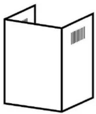
natural_image
Simple line drawing of a cardboard box with visible shipping bars (no text or symbols)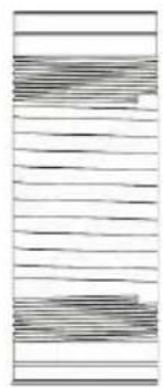
natural_image
Abstract pattern of horizontal lines with no text or symbols7 x wall plugs
7 x large screws
6 x small screws
1 x hood fixing bracket
2 x flue duct fixing bracket
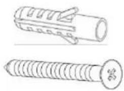
natural_image
Technical line drawings of two types of screw fasteners (no text or symbols)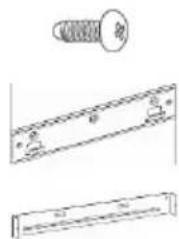
-
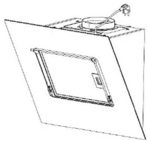
Hood
-
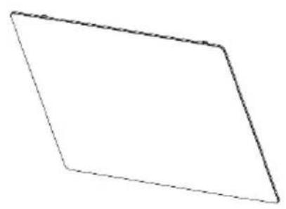
Glass panel
-
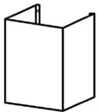
Lower flue duct
-
Upper flue duct
-
Hose
-
Fixtures and fittings
Unit & Spare Parts
If any of the above parts are missing please contact the customer service team on 0345 208 8750 or visit mda.russellhobbs.com
Positioning
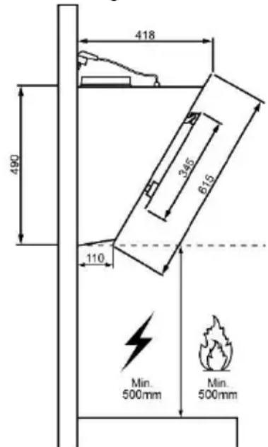
• This appliance is installed on the wall.
- Avoid damaging the product during installation
- The appliance can only be used safely if it is correctly installed according to the safety instructions. The installer is responsible for ensuring that the appliance works correct when installed.
- The width of the extractor hood must correspond at least with the width of the hob.
- For the installation, observe the currently valid building regulations and the regulations of the local electricity and gas suppliers.
- When conveying the exhaust air, official and legal regulations (e.g. state building regulations) must be followed.
- The exhaust air must not be conveyed into a functioning smoke or exhaust gas flue or into a shaft which is used to ventilate installation rooms that contain heating appliances. If the exhaust air is to be conveyed into a non-functioning smoke or exhaust gas flue, you must obtain the consent of the heating engineer responsible.
- Always ensure adequate fresh air in the room if the appliance is being operated in exhaust air mode at the same time as room air-dependent heat-producing appliance is being operated.
All measurements in the below diagram are in millimetres (mm)
Operating modes
This appliance can be used in exhaust-air mode or circulating air mode.
Extraction-air mode
The air which is drawn in is cleaned by the grease filters and extracted outside by a hose.
Important Notes:
- The extracted air must not be extracted into a functioning smoke, exhaust gas flue or into a shaft which is used to ventilate installation rooms which contain heat-producing appliances.
- Before the extracted air is extracted into a non-functioning smoke or exhaust gas flue, obtain the consent of the heating engineer responsible.
- If the extracted air is carried through the outer wall, a telescopic wall box should be used.
Circulating-air mode
The air which is drawn in is cleaned by the grease filters and carbon filters (carbon filters are not supplied with your appliance) and extracted back into the kitchen.
Important Note: To remove odours in circulating-air mode, you must install a carbon filters (carbon filters are not supplied with your appliance). Please contact our customer service team or visit mda.russellhobbs.com to purchase carbon filter.
Dependent on use it is recommended that a carbon filters are changed every 2 – 3 months.
Installation
Preparation
Ensure that there are no electric wires, gas or water pipes in the area where holes are to be made.
- Ensure that there is an electrical plug socket within adequate distance of the hood after it has been installed.
- Mark a vertical centre line on the wall from the ceiling to the lower edge of the extractor hood or below if needed.
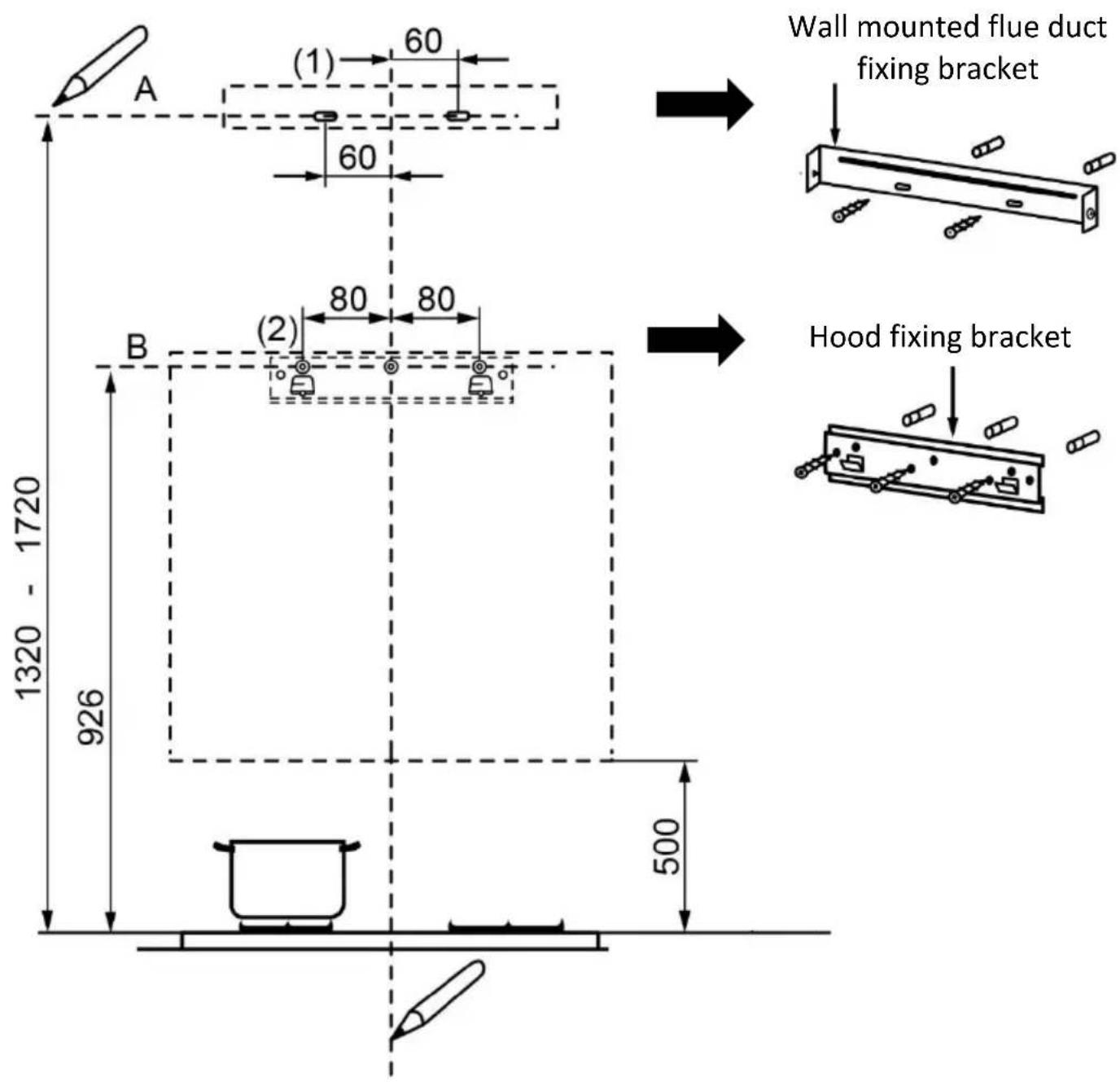
- Mark 2 horizontal lines on the wall, the first should be at a minimum height of 926mm above the cooker top (line B in the diagram on the next page) and the second at 1320mm -1720mm (the height of the line will depend on the height of the ceiling) above the cooker top (line A in the diagram on the next page)
- Mark the contour of the attachment area and the positions for the screws: on line B the marks are to be 80mm either side on the vertical line and on line A the marks are to be 60mm either side of the vertical line.
- Drill 3 x 10mm ∅ holes to a depth of 50mm for the hood fixing bracket (position 2 in the diagram on the next page) and press the wall plugs flush with the wall.
- Drill 2 x 10mm ∅ holes to a depth of 50mm for the wall mounted flue duct fixing bracket (position 1 in the diagram on the next page) and press the wall plugs flush with the wall (at the appropriate height and this will depend on the height of the ceiling).
- Screw on the hood and wall mounted flue duct fixing brackets with the large screws. The flue duct fixing bracket is not installed at this stage (see page 12).
Installation
All measurements in the below diagram are in millimetres (mm)
Installation
Constructing and aligning the appliance.
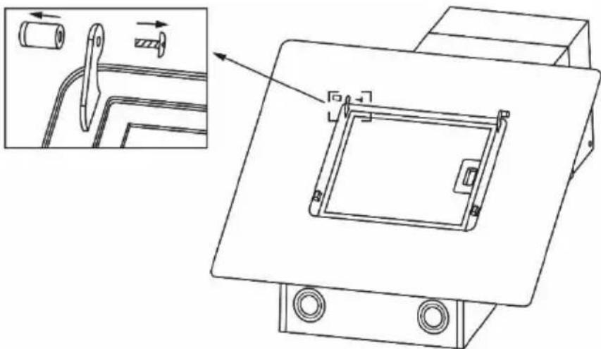
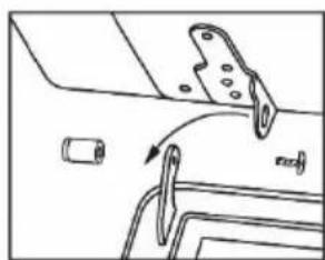
- Loosen and remove the locking shaft and screw from the left hinge bracket on the unit.
natural_image
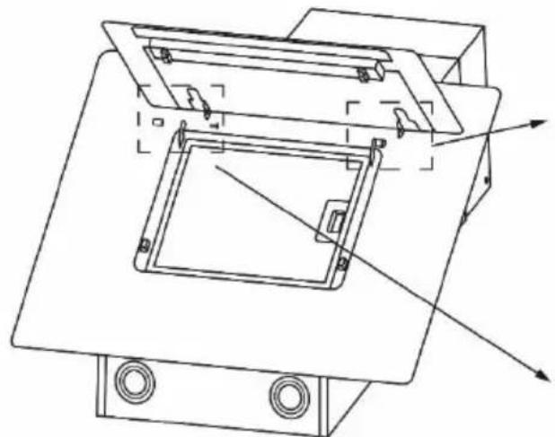
Technical line drawing of a mechanical assembly with component details (no text or symbols)- Carefully hook the right hinge bracket that is on the glass panel on to the left hinge bracket on the unit. Slide the panel to the left until it cannot be moved any further.
- Carefully align the hole on the left hinge bracket on the panel with the hole on the right hinge bracket on the unit. Insert the screw and tighten the locking shaft
natural_image
Technical line drawing of a mechanical assembly with mounting base and internal components (no text or symbols)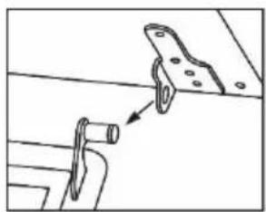
natural_image
Technical line drawing of a mechanical assembly with a bracket and rod (no text or symbols)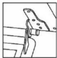
natural_image
Technical line drawing of a mechanical component with no visible text or symbols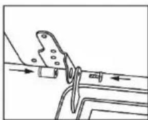
natural_image
Pure mechanical diagram showing a bracket and rod assembly without any text, numbers, or symbols- Carefully close the panel and connect the bottom clips of the panel and unit.
Installation
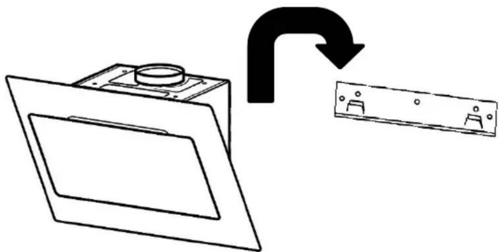
- Partially remove the protective film from the back of the appliance.
- Hook the appliance on to the hood fixing bracket (ensure the hood is fully hooked onto the hood fixing bracket, as the hooks on the bracket are stepped) and check that it is level with a spirit level.
natural_image
Diagram showing a door panel with a circular component and an electrical switch, connected by an arrow indicating rotation (no text or symbols present)- Remove the appliance from the hood fixing bracket and following installation, remove the film completely.
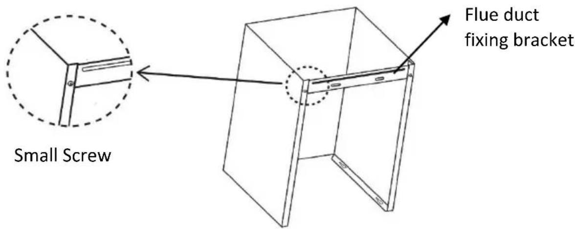
- At the top of the lower (bigger) flue duct secure the flue ducting bracket to the duct with 2 small screws at the rear (1 screw on either side).
Installation
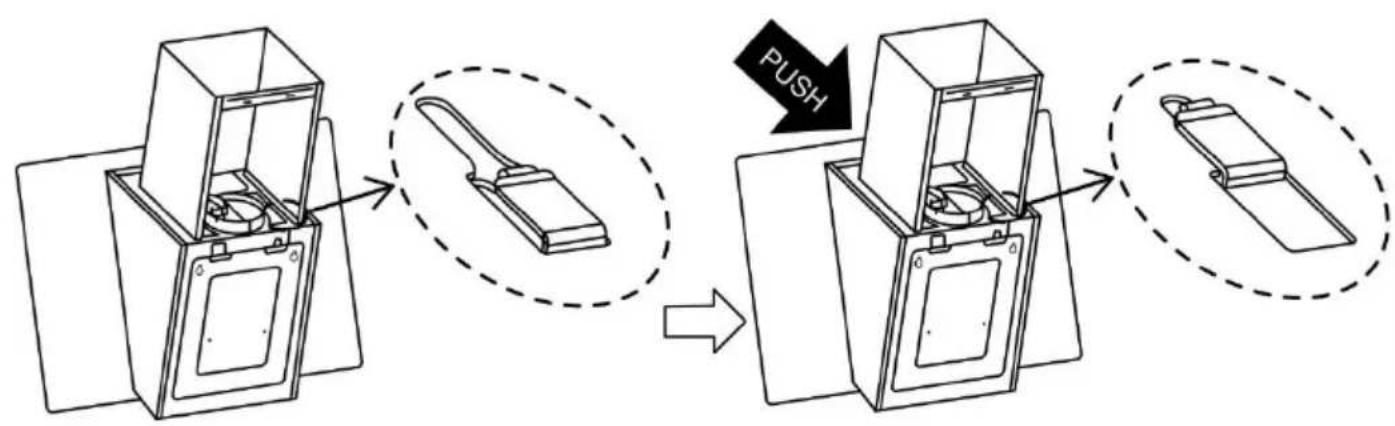
- Attach the lower (bigger) flue duct to the appliance by hooking/pushing the holes on the bottom of the flue duct in to the hooks on the top of the cooker hood. You must ensure the flue ducts is securely attached to the main body of the cooker hood.
flowchart
graph TD
    A["Initial Box with Component"] --> B["Add to a Cable Strip"]
    B --> C["Adjusting Button to Box"]
    C --> D["Final Box with Cable Strip"]
    D --> E["PUSH"]
    style A fill:#f9f,stroke:#333
    style B fill:#ccf,stroke:#333
    style C fill:#cfc,stroke:#333
    style D fill:#fcc,stroke:#333
    style E fill:#ffc,stroke:#333
-
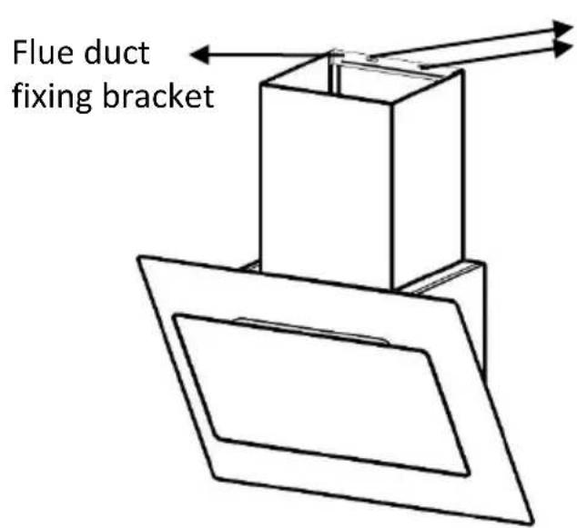
Hook the appliance back onto the hood fixing bracket and mark on the wall the drill hole locations for the flue ducting bracket.
-
Remove the appliance from the hood fixing bracket and drill 2 x 8mm ∅ holes to a depth of 50mm for the flue duct fixing bracket and press the wall plugs flush with the wall.
Drill holes and insert wall plugs
Installation
Attaching the appliance
Components inside the appliance may have sharp edges. Wear protective gloves.
- Slide the upper (smaller) flue duct into the lower (bigger) flue duct.
- Carefully mount the appliance onto the hood fixing bracket (ensure the hood is fully hooked onto the hood fixing bracket, as the hooks on the bracket are stepped)
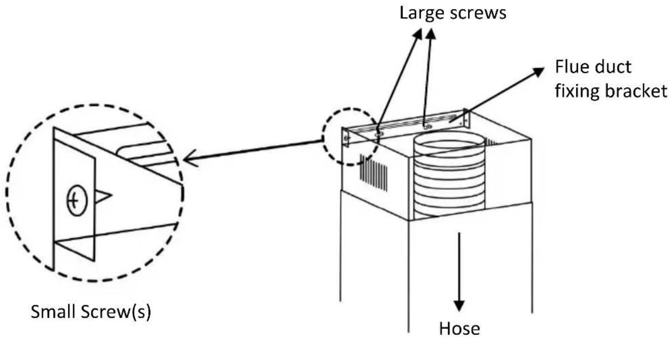
- Screw 2 large screws into the flue duct fixing bracket that is attached to the lower flue duct to secure it to the wall.
- Place the hose on the duct outlet.
- Slide the upper flue duct upwards and screw it to the sides of the wall mounted flue duct fixing bracket previously installed using two small screws.
- Plug the hood into the electrical plug socket and turn on the socket.
Note: Align the flue duct before tightening the screws.
Usage
Note: Switch on the extractor hood when you start cooking and switch it off again several minutes after you have finished cooking. This is the most effective way of removing the kitchen fumes.
Control panel



| Icon Explanation | |
| Light on and off | |
| Fan speed 1 (low) | |
| Fan speed 2 (medium) | |
| Fan speed 3 (high) | |
| Fan off | |
The Fan
Press the fan buttons to set the extraction rate/fan speed that is required
The lighting can be switched on and off independently of the fan.
Press the light button once to turn the lights on and then again to turn the lights off.
Cleaning and Maintenance:
Important notes:
- The appliance will become hot during operation, especially near the bulbs. Allow the appliance to cool down before cleaning.
- Penetrating moisture may result in an electric shock. Clean the appliance using a damp cloth only. Before cleaning, pull out the mains plug or switch off the circuit breaker in the fuse box.
- Do not use any high-pressure cleaners or steam cleaners, which can result in an electric shock.
- Components inside the appliance may have sharp edges. Wear protective gloves.
How to clean
Observe the information in the table on the following page to ensure that the different surfaces are not damaged by using the wrong type of cleaning agent. Do not use:
• Harsh or abrasive cleaning agents,
• Cleaning agents with a high concentration of alcohol,
• Hard scouring pads or sponges,
• High-pressure cleaners or steam cleaners.
Wash new sponge cloths thoroughly before use.
Follow all instructions and warnings included with the cleaning agents.
Cleaning and Maintenance:
| Surface type How to clean | |
| Stainless Steel Hot soapy water: Clean with a dish cloth and dry with a soft cloth.Clean stainless steel surfaces in the direction of the grain only.Special stainless steel cleaning products are from specialist retailers. Apply a very thin layer of the cleaning product with a soft cloth. | |
| Painted surfaces Hot soapy water: Clean using a damp dish cloth and dry with a soft cloth/towel. Do not use any stainless steel cleaners. | |
| Aluminium and plastic Glass cleaner: Clean with a soft cloth. | |
| Glass Glass cleaner: Clean with a soft cloth. Do not use a glass scraper. | |
| Panel Hot soapy water: Clean using a damp dish cloth and dry with a soft cloth. Risk of damage to the electronics from penetrating moisture. Never clean operator controls with a wet cloth.Do not use any stainless steel cleaners. | |
Cleaning and Maintenance:
Aluminium grease filters:
Note: Switch off your hood at the plug socket and unplug it
Removing and installing the Aluminium grease filters:
Removing
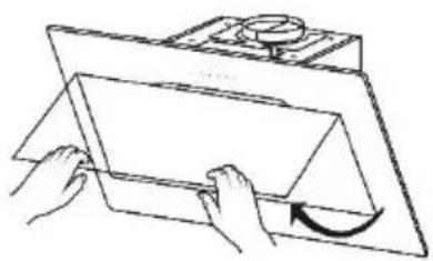
- Push the panel first and then pull it to open.
natural_image
Illustration of hands handling a rectangular object with a curved arrow indicating rotation (no text or symbols)- Press the lock in and pull down the aluminium grease filter.
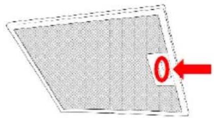
natural_image
Diagram of a grid-patterned panel with a red arrow pointing to the corner (no text or symbols)- Take the filter out of the holder.
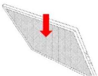
natural_image
3D diagram of a tilted rectangular plate with a red downward arrow indicating compression or stress (no text or symbols)- Clean the filter and allow to dry before replacing (refer to cleaning instructions on the following page).
Cleaning and Maintenance:
Installing
- Insert the aluminium grease filter by aligning the 2 metal tabs into the filter holder.
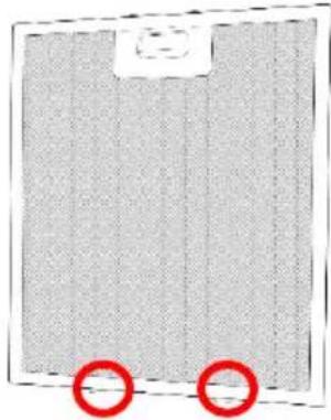
natural_image
Close-up of a textured fabric panel with two red circular markers at the bottom (no visible text or symbols)- Press the lock in and push the filter into place, the let go of the lock to set the filter in place.
Carbon filters (must be purchased separately):
Installing the Carbon grease filters:
- Remove the Aluminium filter(s) from the hood.
- You will now be able to access the motor, carefully attached the carbon filters to both ends of the motor.
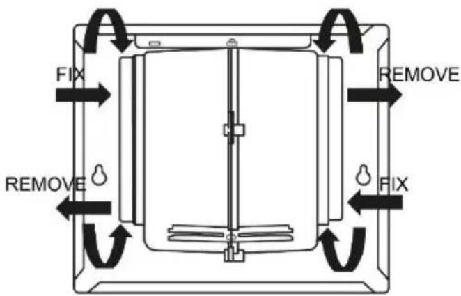
- Carbon filters should be replaced after approximately 2-3 months of use.
- The carbon filters cannot be washed or recycled.
Cleaning and Maintenance:
Important notes
- Grease deposits in the grease filter may catch fire.
- Clean the grease filter at least every 2 months.
- Never operate the appliance without the grease filter.
- Do not use any aggressive, acidic or alkaline cleaning agents.
- When cleaning the aluminium grease filters, also clean the holder filters in the hood using a damp cloth (ensure the hood is turned off).
- The filters can be cleaned in the dishwasher or by hand.
Dishwasher:
- Do not clean heavily soiled metal mesh grease filters together with utensils.
- Place the aluminium grease filters loosely in the dishwasher.
- The filters must not be wedged in.
- The temperature should be 60^ Cor less
Note: If the filters are cleaned in the dishwasher, slight discolouration may occur. This has no effect on the function of the metal mesh grease filters.
By hand:
- Soak the aluminium grease filters in a hot soapy water.
- Clean the filters with a brush before rinsing them thoroughly.
- Leave the filters to drain and put them back in to the hood when dry.
Cleaning and Maintenance:
Replacing the light modules
• You cannot replaced the light bulbs, the entire light module has to be replaced.
- When changing the light modules, the contacts are live.
- Before changing the light module(s), unplug the appliance from the mains or switch off the circuit breaker in the fuse box.
- Only use a light module that is the same type and same power (details below), please contact customer services on 0345 208 8750 or visit mda.russellhobbs.com
| Diameter Mak Power Voltage | Image Lamp cap IL | COS D code | ||
| 70mm 1.5W DC 12V - DSR-1.5 | 5-7 | 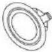 |
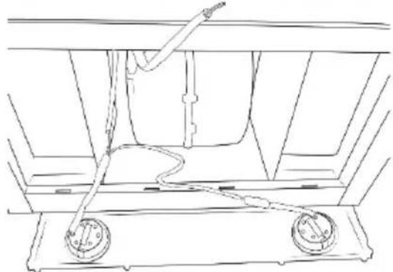
- Remove the grease filter and carefully remove the front plate (a cross headed screwdriver will be needed to remove the screws from the front plate).
natural_image
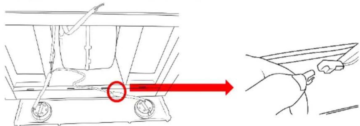
Technical line drawing of a mechanical assembly with two circular components and a connecting rod (no text or symbols)- Unclip the light module from its terminal
Cleaning and Maintenance:
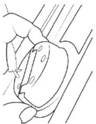
- Remove the light from its fitting (this may require pressure or force to be applied).
natural_image
Line drawing of a hand holding a tool near a mechanical component (no text or symbols)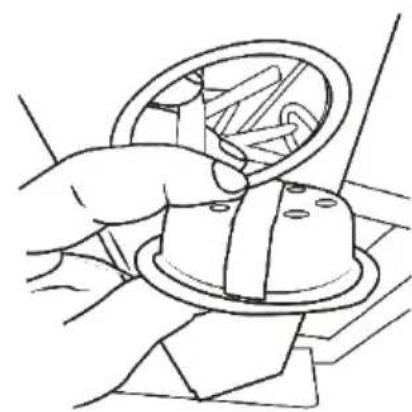
natural_image
Line drawing of a hand holding a circular object with a ring, possibly a knob or dial (no text or symbols)- Put the replacement light module into the fitting (ensuring the terminal is threaded through the fitting) and connect it to the terminal.
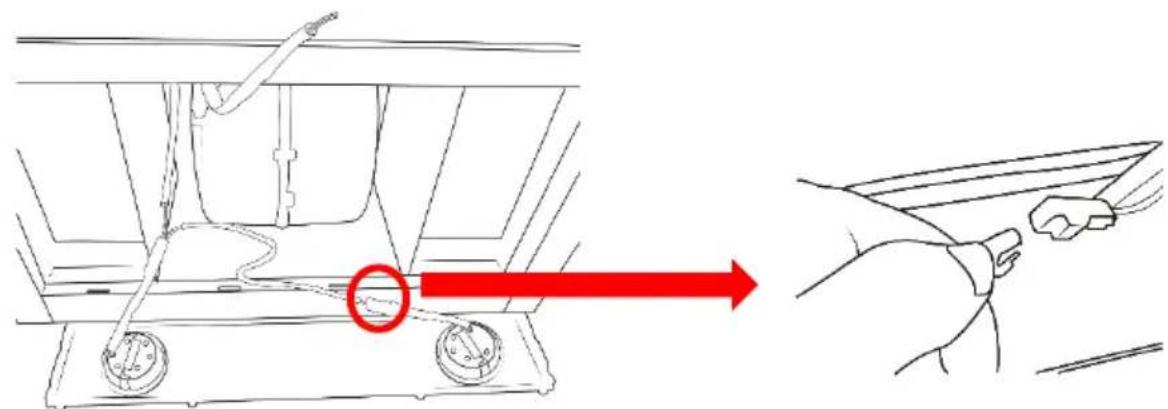
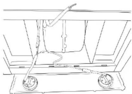
- Replace the Aluminium grease filter and plug the appliance back into the mains or switch on the circuit breaker in the fuse box
natural_image
Technical line drawing of a mechanical assembly with two circular components and a connecting rod (no text or symbols)Trouble Shooting:
| Problem Solution | |
| The appliance does not work | The plug is not plugged in. Connect the appliance to the electricity supply. |
| Power cut Check whether other kitchen appliances are working. | |
| Faulty fuse Check in the fuse box to make sure that the fuse for the appliance is working | |
| The fan is faulty. Contact our customer engagement or a local engineer. | |
| The lighting does not work | The plug is not plugged in Connect the appliance to the electricity supply. |
| The bulbs are faulty. For information on changing the bulbs, see the "Replacing Bulbs" section. | |
| Excessive vibration | The hood is not correctly installed, check all screws are tightly fastened. |
| Insufficient suction | The hood may have been installed too far away from the hob. |
| The hood is not flush against the wall | The screws of the fixing brackets have not been tightened sufficiently. |
Connection to the mains supply
WARNING- THIS APPLIANCE MUST BE EARTHED
This appliance is designed to operate from a mains supply of AC220V-AC240V\~50Hz. Check that the voltage marked on the product corresponds with your supply voltage.
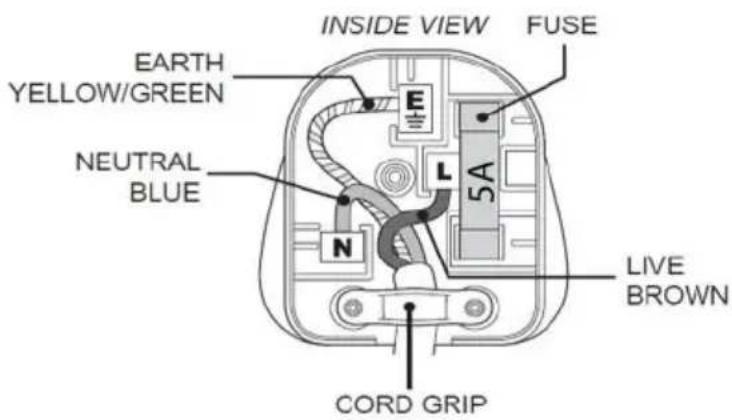
For UK use only – Plug fitting details (where applicable):
As the colours of the wires in the mains lead of this appliance may not correspond with the coloured markings identifying the terminals in your plug, proceed as follows:
The GREEN/YELLOW wire is the EARTH and must be connected to the terminal which is marked with the letter E or by the earth symbol or coloured GREEN or
GREEN/YELLOW.
The BLUE wire is the NEUTRAL and must be connected to the terminal marked with the letter N or coloured BLACK.
The BROWN wire is the LIVE wire and must be connected to the terminal marked with the letter L or coloured RED.
Always ensure that the plug cord grip is fastened correctly.

natural_image
Warning symbol depicting a lightning bolt inside a triangle (no text or numbers)DANGER Electric Shock Risk
If a 5A (BS1363) fused plug is used it must be fitted with a 5amp fuse conforming to BS1362 and be BSI or ASTA approved.
Guarantee
This product is guaranteed for 12 months from the date of the original purchase. If any defect arises due to faulty materials or workmanship you must contact Product Care with the original proof of purchase so a replacement or refund can be arranged.
Refund or replacement is at the discretion of Product Care.
The following conditions apply:
- Product Care will require a valid proof of purchase at the point of replacement or refund.
- The product must be installed and used in accordance with the instructions contained in this instruction guide and any other instructions for use which has been supplied.
- It must be used for domestic purposes only and for its intended use.
- This guarantee does not cover wear and tear, damage, misuse or consumable parts.
This does not affect your statutory rights.
Technical Specification
Model number RHGCH902B-M
Rated Voltage 220V – 240V \~ 50Hz
Rated input 218W
External Dimensions(HxWxD) 535 - 1250mm x 900mm x 420mm
Extraction rate 630m^3/h
Light power 2 x 1.5W LED bulbs

Russell Hobbs
Russell Hobbs is a registered trademark used under license from Spectrum Brands (UK) Ltd. Made under license by G2S Limited, Wigan, WN2 4AY/G2S (NI) Ltd, Belfast, BT5 5AD.
Russell Hobbs Support: call 0345 208 8750 or visit: mda.russellhobbs.com


The 'wheelie bin' symbol is known as the 'Crossed-out wheelie bin Symbol'.
When this symbol is marked on a product/batteries, it means that the product/batteries should not be disposed of with your general household waste. Only discard electrical/electronic/battery items in separate collection schemes, which cater for the recovery and recycling of materials contained within. Your co-operation is vital to ensure the success of these schemes and for the protection of the environment. For your nearest disposal facility, visit www.recycle-more.co.uk or ask in store for details.
SEDEX – Connecting businesses and their global suppliers to share ethical data and enabling improvement in ethical performance. Visit www.sedex.org.uk for further information.
We reserve the right, due to possible changes to design, to alter the instruction manual without prior notice.
Revision 3.1
- Contents
- Safety Instructions
- Important note:
- Product overview
- Unit & Spare Parts
- Positioning
- Operating modes
- Extraction-air mode
- Important Notes:
- Circulating-air mode
- Installation
- Preparation
- Constructing and aligning the appliance.
- Attaching the appliance
- Usage
- Control panel
- The Fan
- Cleaning and Maintenance:
- How to clean
- Aluminium grease filters:
- Removing and installing the Aluminium grease filters:
- Removing
- Installing
- Carbon filters (must be purchased separately):
- Installing the Carbon grease filters:
- Important notes
- Dishwasher:
- By hand:
- Replacing the light modules
- Connection to the mains supply
- Guarantee
- The following conditions apply:
- Technical Specification
- Russell Hobbs
- Revision 3.1
Brand : RUSSELL HOBBS
Model : RHGCH902B-M
Category : Range hood