MI-7285 - Mount Mount-It! - Free user manual and instructions
Find the device manual for free MI-7285 Mount-It! in PDF.


| Product Type | On-Wall TV Cable Concealer Kit |
| Brand | Mount-It! |
| Model | MI-7285 |
| Installation Options | Adhesive tape or screw mounting (concrete anchors) |
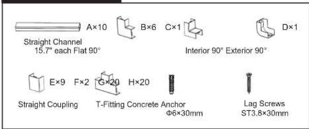
| Components Included | Straight channels, flat 90° connectors, interior 90° connectors, exterior 90° connectors, T-fittings, straight couplings, covers, adhesive tape, screws, concrete anchors |
| Channel Length Adjustment | Cuttable to desired length using a hand saw |
| Compatible Surfaces (Adhesive) | Smooth, clean surfaces; not suitable for rough or uneven walls |
| Compatible Surfaces (Screw) | Stone or concrete walls; not for drywall or wood studs |
| Drill Bit Size (Screw Mount) | 1/2 inch (6 mm) |
| Drill Hole Depth (Screw Mount) | 1.38 inches (35 mm) |
| Additional Length for Connectors | Flat/Exterior 90°: +0.63 in (16 mm); Interior 90°: +1.3 in (33 mm); T-Fitting: +2.36 in (60 mm) per end; Straight Coupling: +0.71 in (18 mm) |
| Intended Use | Indoor use only; decorative cable concealment, not structural conduit |
| Safety Warnings | Choking hazard for small parts; not for children under 3; do not over-tighten screws; avoid routing uninsulated/damaged wiring |
| Maintenance | Check secureness every 3 months; remove adhesive tape by heating with hairdryer if reinstallation needed |
| Customer Support | Email: support@mount-it.com; Phone: (855) 925-5668 (Mon-Fri, 8am-4pm PST); Live chat at www.mount-it.com |
| Warranty Information | Available at www.mount-it.com (product registration) |
Frequently Asked Questions - MI-7285 Mount-It!
User questions about MI-7285 Mount-It!
0 question about this device. Answer the ones you know or ask your own.
Ask a new question about this device
Download the instructions for your Mount in PDF format for free! Find your manual MI-7285 - Mount-It! and take your electronic device back in hand. On this page are published all the documents necessary for the use of your device. MI-7285 by Mount-It!.
USER MANUAL MI-7285 Mount-It!
natural_image
Technical line drawing of a mechanical bracket assembly with no visible text or symbols
Scan this QR code for product information, videos, and assembly assistance.
ON-WALL TV CABLE CONCEALER KIT

HAVE QUESTIONS?
Monday - Friday from 8:00am - 4:00pm PST

support@mount-it.com

(855) 925-5668

www.mount-it.com
Thank you for choosing Mount-It!
EN Read the entire instruction manual before you start installation and assembly. If you have any questions regarding any of the instructions or warnings, please contact Mount-It for assistance.
CAUTION: - Please closely follow the assembly instructions. Improper installation may result in damage or serious personal injury. - Use the mounting screws provided and DO NOT OVER TIGHTEN mounting screws.
• This product contains small items that could be a choking hazard if swallowed. Keep these items away from children.
* This product is intended for indoor use only. Using this product outdoors could lead to product failure and personal injury. IMPORTANT: Ensure that you have received all pads according to the component checklist prior to installation. If any pads are missing or
IMPORTANT: Ensure that you have recently faulty contact Mount H for a replacement.
MAINTENANCE: Check that the product is secure and safe to use at regular intervals (at least every three months).
WARNING
- Due to the extremely sticky nature of the tape, please plan your installation well in advance of installation to avoid removing and reinstalling the cable channel. If it is necessary to unplug the channel, try to soften the bottom of the raceway by heating it with a Hair Dryer (not too high a temperature is recommended) and then gently peel it off.
- The channels can be cut to a shorter length if needed, please take all proper safety precautions when cutting and beware of possible sharp edges left over.
- It is not recommended that the channel be mounted on an uneven wall, if you do need to mount on a rough wall, use screw mounting rather than double sided tape.
- Do not use this product to route uninsulated, exposed, or damaged wiring.
- This product is intended to route and conceal cables for decorative purposes, it may not be used as a structural cable conduit.
PACKAGE CONTENTS
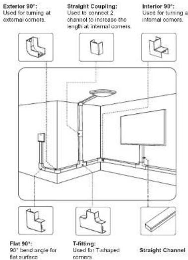
Please refer to the diagram below for instructions on how to use each connector and select your desired mounting method.
Check carefully to make sure there are no missing or defective parts. Some hardware provided may not be used. Use the correct mounting hardware suitable for your installation.
CHOKING HAZARD. Package includes small parts. Not for children under 3 years. Adult supervision is required.
Missing Parts? Call us at (855) 925-5668 and we will ship replacement parts free of charge.
Installation Option 1: Adhesive Tape
(Not suitable for rough or uneven surfaces)
Step 1
Clean the Wall Surface
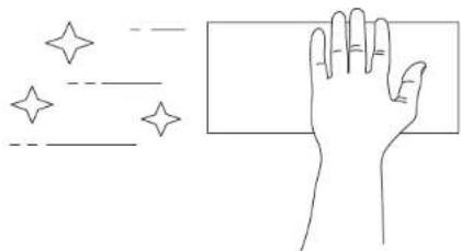
- Wipe the mounting area clean with a cloth or a duster. If the walls were cleaned using a liquid cleaner, allow the surface to fully dry before proceeding.
natural_image
Line drawing of a hand holding a rectangular object with star patterns (no text or symbols)Step 2
Measure
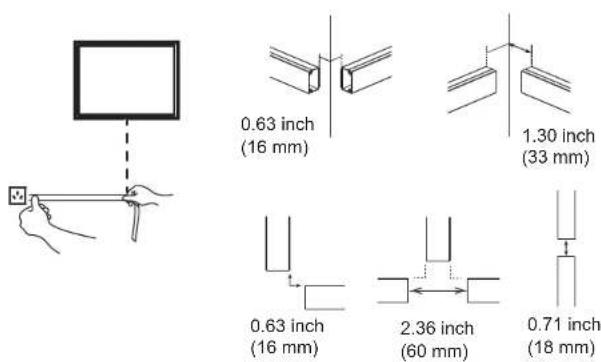
- First, plan the route and mark it with a pencil, then measure the distance and determine the number of cable channels needed and the number of connectors and each type. Refer to the diagram to determine the exact spacing of each connector.
• To each Straight Channel (#A) add additional length to accommodate the connectors used: - Add 0.63" (16mm) for each Flat 90° (#B) or Exterior 90° (#D).
- Add 1.3" (33mm) for each Interior 90° (#C).
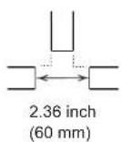
- Add 2.36" (60mm) for each end of the T-Fitting (#F)
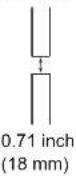
- Add 0.71" (18mm) for each Straight Coupling (#E)
Step 3
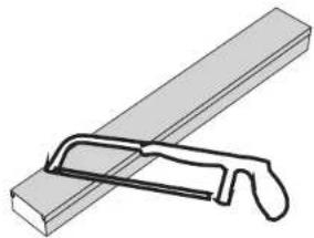
Optional: Cut the Straight Channel as Needed
- If any of the Straight Channels (4A) exceed the required length, mark the correct length, and cut in the marked location with a hand saw.
natural_image
Simple line drawing of a diagonal bar with a handle, no text or symbols presentStep 4
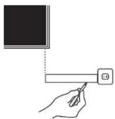
Determine Final Placement
- Using a bubble level to ensure straightness, hold the Straight Channels (#A) in their positions and mark the edge locations with a pencil.
natural_image
Hand holding a pen and a smartphone with an icon, no text or symbols presentStep 5
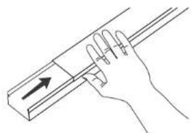
Remove the Cover
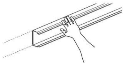
- Remove the cover plates from the Straight Channels (#A) by sliding the top until it separates fully from the bottom piece.
natural_image
Hand holding a tool with an arrow indicating direction (no text or symbols)Step 6
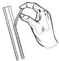
Remove Adhesive Backing
- Remove the adhesive backing from the rear of the Straight Channels (#A) exposing the mounting tape beneath.
natural_image
Line drawing of a hand holding a curved object next to a vertical rod (no text or symbols)Step 7
Stick the Channels to the Wall
- Align the channels with the markings and press the Straight Channels (#A) firmly in place on the wall.
natural_image
Line drawing of a hand adjusting a 3D rectangular object with dashed lines indicating alignment (no text or symbols)Step 8
Route the Cables
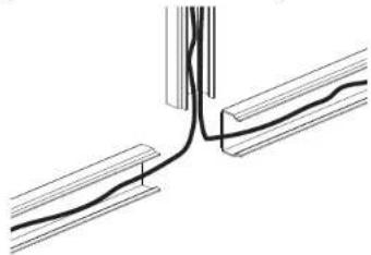
- Route the cables through the channels. If multiple cables are used, ensure they are laid side by side and not overlapping so the cable channel can be closed easily.
natural_image
Pure technical line drawing of a mechanical joint or connection (no text or symbols)6
MOUNT-IT!
Step 9
Install the Connectors & Covers
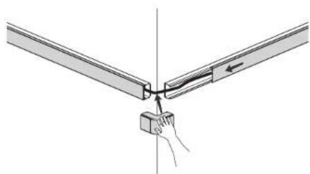
- First, reinstall the covers onto the Straight Channel, then install the connectors onto any corners or turns in your assembly by pressing them into place over the corresponding ends of the channels.
natural_image
Diagram showing a hand inserting a component into a Y-shaped structure with a directional arrow (no text or symbols)Installation Option 2: Screws and Concrete Anchors
(Only for stone/concrete walls)
Step 1
Clean the Wall Surface
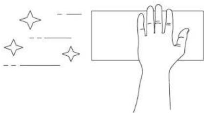
- Wipe the mounting area clean with a cloth or a duster. If the walls were cleaned using a liquid cleaner, allow the surface to fully dry before proceeding.
natural_image
Line drawing of a hand holding a rectangular object with star patterns (no text or symbols)MOUNT-IT!
7
Step 2
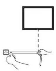
Measure
- First, plan the route and mark it with a pencil, then measure the distance and determine the number of cable channels needed and the number of connectors and each type. Refer to the diagram to determine the exact spacing of each connector.
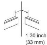
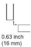
- To each Straight Channel (#A) add additional length to accommodate the connectors used:
- Add 0.63" (16mm) for each Flat 90° (#B) or Exterior 90° (#D).
- Add 1.3" (33mm) for each Interior 90" (#C).
- Add 2.36" (60mm) for each end of the T-Fitting (#F)
- Add 0.71" (18mm) for each Straight Coupling (#E)
natural_image
Illustration of hands holding a small object with a ruler, next to a blank rectangular frame (no text or symbols)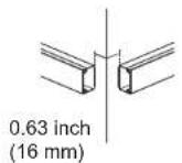
Step 3
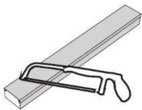
Optional: Cut the Straight Channel as Needed
- If any of the Straight Channels (#A) exceed the required length, mark the correct length, and cut in the marked location with a hand saw.
natural_image
Simple line drawing of a diagonal tool interacting with a rectangular block (no text or symbols)Step 4
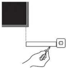
Determine Final Placement
- Using a bubble level to ensure straightness, hold the Straight Channels (#A) in their positions and mark the end positions with a pencil.
natural_image
Hand holding a pen and pointing at a screen with a small icon (no text or symbols)Step 5
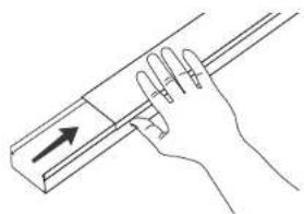
Remove the Cover
- Remove the cover plates from the Straight Channels (#A) by sliding the top until it separates fully from the bottom piece.
natural_image
Hand holding a tool with an arrow indicating direction (no text or symbols present)Step 6
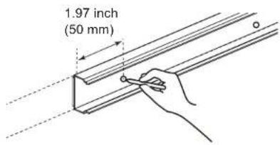
Mark the Screw Locations
• Using a pencil make a mark centered on each end of the Straight Channels (#A) 1.97" (50mm) from the ends.
Step 7
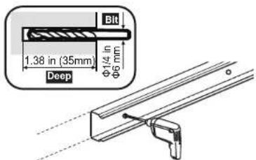
Attach the Channels to the Wall
- Align the channels with the markings and hold the Straight Channels (#A) in place on the wall. Drill holes in the marked locations using a 12 " drill bit (6mm) to a depth of 1.38" (35mm).
Step 8
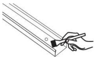
Clean Any Dust
- Remove the channel from the wall and clean any dust.
natural_image
Line drawing of a hand holding a tool over a wooden plank (no text or symbols)Step 9
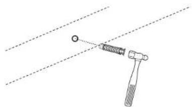
Insert Concrete Anchors
- Insert the Concrete Anchors (#G) until they are fully inserted into the drilled holes. This may require a hammer to tap them fully into place.
WARNING: Concrete anchors are for solid stone and concrete use only and are not suitable for use with drywall or wood studs.
natural_image
Simple line drawing of a hammer striking a circular object with a pointer, intersected by two diagonal lines (no text or symbols)10
MOUNT-IT!
Step 10
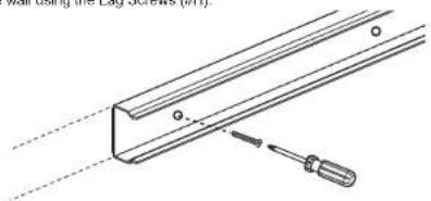
Mount the Channels
- Hold the Straight Channels (#A) to the wall and align them with the concrete anchors. Attach the channels to the wall using the Lag Screws (#H).
natural_image
Technical line drawing of a mechanical component with a screwdriver inserted, no text or symbols presentStep 11
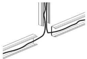
Route the Cables
- Route the cables through the channels. If multiple cables are used, ensure they are laid side by side and not overlapping so the cable channel can be closed easily.
natural_image
Pure technical line drawing of a mechanical joint or connection (no text or symbols)Step 12
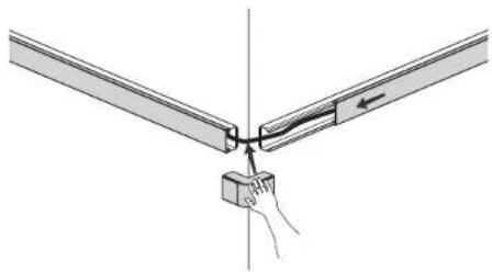
Install the Connectors & Covers
- First, reinstall the covers onto the Straight Channel, then install the connectors onto any corners or turns in your assembly by pressing them into place over the corresponding ends of the channels.
natural_image
Diagram showing two vertical bars connected by a cable with a small box and hand holding a pointer (no text or symbols)MOUNT-IT!
11
Visit us at www.mount-it.com for product registration and warranty information.
Our US based customer service team is standing by to answer any questions you have about your Mount-It! product.
Available by phone Monday - Friday from 8:00am to 4:00pm PST.
Chat live with an agent on our website!

support@mount-it.com

(855) 925-5668

www.mount-it.com
- ON-WALL TV CABLE CONCEALER KIT
- Thank you for choosing Mount-It!
- WARNING
- Installation Option 1: Adhesive Tape
- Step 1
- Clean the Wall Surface
- Step 2
- Measure
- Step 3
- Optional: Cut the Straight Channel as Needed
- Step 4
- Determine Final Placement
- Step 5
- Remove the Cover
- Step 6
- Remove Adhesive Backing
- Step 7
- Stick the Channels to the Wall
- Step 8
- Route the Cables
- Step 9
- Install the Connectors & Covers
- Installation Option 2: Screws and Concrete Anchors
- Mark the Screw Locations
- Attach the Channels to the Wall
- Clean Any Dust
- Insert Concrete Anchors
- Step 10
- Mount the Channels
- Step 11
- Step 12
Brand : Mount-It!
Model : MI-7285
Category : Mount