
PMM-2 - Measurement Megger - Free user manual and instructions
Find the device manual for free PMM-2 Megger in PDF.


| Product Type | Power Quality Meter |
| Brand | Megger |
| Model | PMM-2 |
| Dimensions (approx.) | 200 x 100 x 50 mm |
| Weight (approx.) | 0.5 kg |
| Power Supply | 2 x AA batteries |
| Measurement Functions | Voltage, Current, Power, Frequency, Harmonics, Power Factor |
| Display | Backlit LCD |
| Data Logging | Internal memory for trend recording |
| Communication | USB for data download |
| Safety Rating | CAT III 600V |
| Operating Temperature | 0°C to 50°C |
| Storage Temperature | -20°C to 60°C |
| Maintenance | Wipe with dry cloth; no calibration required |
| Spare Parts | Test leads, batteries |
| Reparability | Replaceable fuses and batteries; service center available |
| General Information | Used for power quality analysis in industrial and commercial settings |
Frequently Asked Questions - PMM-2 Megger
User questions about PMM-2 Megger
0 question about this device. Answer the ones you know or ask your own.
Ask a new question about this device
Download the instructions for your Measurement in PDF format for free! Find your manual PMM-2 - Megger and take your electronic device back in hand. On this page are published all the documents necessary for the use of your device. PMM-2 by Megger.
USER MANUAL PMM-2 Megger
This user guide, as well as the hardware and software described in it, is furnished under license, and may be used or copied only in accordance with the terms of such license. The content of this user guide is furnished for informational use only and is subject to change without notice. Megger assumes no responsibility or liability for any errors or inaccuracies that may appear in this user guide.
The information and data in this user guide are proprietary. The equipment described herein may be protected by U.S. patents. Megger specifically reserves all rights to such proprietary information as well as rights under any patent, none of which is waived by the submission of this user guide.
Except as permitted by such license, no part of this publication may be reproduced, stored in a retrieval system, or transmitted, in any form or by any means, electronic, mechanical, recording, or otherwise, without the prior written permission of Megger.
Megger, the Megger logo are trademarks of Megger. All other trademarks are the property of their respective owners.
Notice to U.S. government end users. The hardware, software and documentation are “commercial items,” as that term is defined at 48 C.F.R. §2.101, consisting of “commercial computer software” and “commercial computer software documentation,” as such terms are used in 48 C.F.R. §12.212 or 48 C.F.R. §227.7202, as applicable. Consistent with 48 C.F.R. §12.212 or 48 C.F.R. §§227.7202-1 through 227.7202-4, as applicable, the commercial computer software and commercial computer software documentation are being licensed to U.S. government end users (1) only as commercial items and (2) with only those rights as are granted to all other end users pursuant to the terms and conditions set forth in the Megger standard commercial agreement for this software and hardware. Unpublished rights reserved under the copyright laws of the United States. The recipient, if a government agency, acknowledges that this user guide and the equipment described were procured with "Limited Rights" to technical data as described in ASPR 9-203 (b).
The onboard display includes an RTOS-resident computer program. This program belongs to Megger and contains trade secret ideas and information of Megger, written and designed at Megger, 4545 W. Davis, Dallas, Texas 75211-3422 USA
© 2022
This document is the copyright of:
Megger Limited, 4545 W Davis Street
Dallas, Texas 75211-3422 USA
PHONE: (800) 723-2861
FAX: (214) 331-7399
www.megger.com
Megger reserves the right to alter the specification of its products from time to time without notice. Although every effort is made to ensure the accuracy of the information contained within this document it is not warranted or represented by Megger Limited to be a complete and up-to-date description.
For patent information about this instrument refer to the following web site: megger.com/patent
Revision history
| Revision | ECN # | Date |
| 1 | 87865 | 9/01/2022 |
Declaration of conformity
Hereby, Megger Instruments Limited declares that the PMM-2, manufactured by Megger Instruments Limited described in this user guide, is following Directive 2014/53/EU. The full text of Megger Instruments EU declarations of conformity is available at the following internet address:
Megger.com/Company/About-Us/Legal/EU declarations of conformity
Table of contents
IMPORTANT....2
REVISION HISTORY....3
TABLE OF FIGURES ......7
1.0 INTRODUCTION....9
1.1 PRODUCT DESCRIPTION ...... 9
1.2 FEATURES....9
1.3 APPLICATIONS .... 10
1.4 MEGGER WEBSITE 10
2.0 SAFETY WARNINGS AND STANDARDS....11
2.1 WARNINGS, CAUTIONS AND NOTES....11

2.2 ADDITIONAL SAFETY WARNINGS....12
3.0 INSTRUMENT OVERVIEW....13
3.1 PMM-2 ONBOARD DISPLAY SCREEN AND POWER INPUT 13
3.2 INPUT POWER CORD 14
3.3 TOP PANEL COMMUNICATION PORTS AND INPUT TERMINALS....15
3.4 CONFIGURATION OF PMM-2 SOFTWARE....16
3.4.1 Configuration 17
3.4.2 System configuration options 18
3.4.2.3 Label settings 18
3.4.2.3.1 Voltage character.... 19
3.4.2.4 Global settings 19
3.4.2.4.1 Language 19
3.4.2.4.2 Set system date and time....19
3.4.2.4.3 System info (information screen) 19
3.4.2.5 Screen dimming.... 20
3.4.2.6 Sample settings.... 20
3.4.2.6.1 Fundamental frequency 20
3.4.2.6.2 Waveform capture rate.... 20
3.4.2.6.3 Pre-trigger samples 20
3.4.2.7 Diagnostic logging settings.... 21
3.4.3 Phase angle configuration screen 21
3.4.4 CT/PT ratios....21
3.4.6 Colors options....22
4.0 GENERAL OPERATING INSTRUCTIONS....23
4.1 SAFETY CONSIDERATIONS....23
4.2 SET UP OF PMM-2 23
4.2.1 Unpack system 23
4.2.2 Initial startup....24
4.2.3 Battery 24
4.2.3.1 Battery charging 24
4.3 MAIN STARTUP SCREEN 25
4.3.1 ① Connection button....25
4.3.2 ② The configuration button 25
4.3.3 ③ Report options button 25
4.3.4 ④ Timer configuration button 26
4.3.4.1 Timer configuration....27
4.3.9 ⑧ Select panels and charts to display button....31
4.3.9.1 Enable current/frequency panel.... 31
4.3.9.2 Enable current panel 31
4.3.9.3 Enable voltage/frequency panel 32
4.3.9.4 Enable voltage panel.... 32
4.3.9.5 Enable frequency panel.... 32
4.3.9.6 Enable power panel.... 33
4.3.9.7 Enable VA/PF panel 33
4.3.9.8 Enable timer panel 34
4.3.9.9 Charts off.... 34
4.3.9.10 Combined waveform mode 35
4.3.9.11 Combined waveform with binary mode 35
4.3.9.12 Polar mode 36
4.3.9.13 Polar mode with binary.... 36
4.3.9.14 Split waveform mode 37
4.3.9.15 Harmonics mode 37
4.3.10 ⑨ Voltage and current general settings options 38
4.3.10.1 Voltage general settings options 38
4.3.10.1.1 Voltage channel enable/disable switch 38
4.3.10.1.2 Voltage channel mode options 38
4.3.10.1.3 Voltage channel integration cycles 39
4.3.10.1.4 Voltage channel integration seconds 39
4.3.10.1.5 Voltage channel range options 39
4.3.10.1.6 Voltage channel trigger setting options.... 39
4.3.10.1.7 Voltage channel low pass filter 40
4.3.10.1.8 Voltage channel external CT settings.... 40
4.3.10.2 Current general settings options.... 40
4.3.10.2.1 Current channel enable/disable switch 41
4.3.10.2.2 Current channel mode options.... 41
4.3.10.2.3 Current channel integration cycles.... 41
4.3.10.2.4 Current channel DC integration seconds.... 41
4.3.10.2.5 Current channel range options.... 41
4.3.10.2.6 Current channel trigger setting options 42
4.3.10.2.7 Current channel low pass filter 42
4.3.10.2.8 Current channel external CT settings 42
4.3.10.3 Phase reference.... 42
4.3.11 ⑩ Freeze button 43
4.3.12 ⑪ Help ? button....43
4.3.13 ⑫ File folder button 43
4.3.14 ⑬ Battery icon 43
4.3.15 ⑭ Graphic display screen.... 43
4.3.15.1 Graphic display zoom button 44
4.3.16 Binary Inputs #1 and #2 status.... 44
5.0 APPLICATIONS 44
5.1.1 Single-phase to neutral current and voltage example 45
5.1.2 1-phase, 2-wire, 1 12 element with CTs example 47
5.2 THREE-PHASE OPERATION 48
5.2.1 Selecting the configuration 49
5.2.2 Measuring functions 49
5.2.3 Clamp-on current and potential transformer operation 50
5.2.3.1 Measuring primary current with clamp-on CT 50
5.2.3.2 Verifying the ratios of CTs....51
5.3 TIMING TESTS....52
5.3.1 Timing test using binary inputs....53
5.3.2 Timing test using current start.... 53
5.4 TIMED DATA RECORDING 54
5.5 PMM-2 software file management 55
5.5.1 File management main screen 56
5.5.1.1 Forms and form results folder 56
5.5.1.2 Snapshots folder.... 56
5.5.1.3 Recordings folder 57
5.5.1.4 Logs folder....57
5.5.1.5 Software updates....57
6.0 MAINTENANCE....57
6.1 GENERAL MAINTENANCE....57
6.2 CLEANING....57
6.3 BATTERY....58
6.3.1 Battery status....58
6.4 UPDATING PMM-2 SOFTWARE AND FIRMWARE 58
7.0 BATTERY REPLACEMENT....58
8.0 SPECIFICATIONS 59
9.0 ACCESSORIES....62
9.1 INCLUDED ACCESSORIES....62
9.2 TABLE OF OPTIONAL ACCESSORIES....62
10.0 CALIBRATION, REPAIR, AND WARRANTY 66
10.1 WARRANTY....66
10.2 RETURN PROCEDURE 67
11.0 DECOMMISSIONING 67
11.1 WEEE DIRECTIVE 67
11.2 PMM-2 AND BATTERY DISPOSAL 68
Table of figures
Figure 1: PMM-2 touch screen and power input....13
Figure 2: Communication ports and input terminals 15
Figure 3: Main startup screen 16
Figure 4: System configuration screen .... 17
Figure 5: Enter new profile name....18
Figure 6: Changing channel 4 name with the alphanumeric keyboard 19
Figure 7: System info screen 20
Figure 8: Phase Angle Configuration Setting screen 21
Figure 9: CT/PT ratios input selection screen....22
Figure 10: Primary values displayed with split screen waveforms....22
Figure 11: Color options....23
Figure 12: Main startup screen identifications ....25
Figure 13: Reports options – customs form available in the software ...... 26
Figure 14: Timer configuration screen 27
Figure 15: Timer start/stop conditions menu....27
Figure 16: Channel select for analog start/stop 28
Figure 17: Timer mode selection screen....28
Figure 18: Binary input configuration screen .... 29
Figure 19: Programmable voltage threshold setting 29
Figure 20: Snapshot options screen 30
Figure 21: Select panels to display screen .... 31
Figure 22: Enabled current/frequency panel....31
Figure 23: Enabled current panel.... 32
Figure 24: Enabled voltage/frequency panel .... 32
Figure 25: Enabled voltage panel 32
Figure 26: Enabled frequency panel 33
Figure 27: Enabled Watts and VARs 33
Figure 28: Enabled VA/PF (power factor) panel 33
Figure 29: Enabled timer panel....34
Figure 30: Select chart mode screen 34
Figure 31: Charts off screen .... 34
Figure 32: Combined waveform screen 35
Figure 33: Combined waveform with binary screen.... 35
Figure 34: Polar plot of 3-phase voltage and current vectors 36
Figure 35: Polar plot of 3-phase voltage and current vectors and binary inputs.... 36
Figure 36: Split waveform screen .... 37
Figure 37: Harmonics display screen....37
Figure 38: Voltage and current general settings screen 38
Figure 39: Voltage channel modes 38
Figure 40: Voltage ranges....39
Figure 41: Voltage channels used to measure current via external CTs 40
Figure 42: Current channels configuration screen....40
Figure 43: Current channel modes 41
Figure 44: Current ranges....42
Figure 45: Phase reference selection list....43
Figure 46: Example zoom of l1 3rd and 5th harmonic distorted waveform....44
Figure 47: Binary #1 and #2 graphic icons in graphic window....44
Figure 48: Single-phase voltage and current direct connection....45
Figure 49: Single-phase voltage and current using CT/PT connections....45
Figure 50: Single-phase IA and VA with combined waveforms 46
Figure 51: Single-phase with split waveform option....46
Figure 52: 1-phase, 2 wire, 1 12 element with CTs example test connections....47
Figure 53: 1-phase, 2 wire ,1½ element example with combined waveforms ..... 48
Figure 54: 1-phase, 2 wire, 1 12 element example with split waveform option.... 48
Figure 55: Three-phase, 4 wire, 3 element connections....49
Figure 56: Example three-phase wye power measurements....50
Figure 57: Current general settings screen....51
Figure 58: Example panels to display for CT testing .... 52
Figure 59: Checking CT ratio with clamp-on CT 52
Figure 60: Example recorder capture options screen....54
Figure 61: File folder main screen .... 55
Figure 62: Example recording data file .... 55
Figure 63: File management main screen .... 56
Figure 64: Example three-phase snapshot screen shot 56
1.0 Introduction
This user guide contains information regarding the correct use and safe handling of the POWER MULTIMETER Model PMM-2. This user guide can be found by pressing the “?” Help button located on the main screen of the PMM-2 software on the onboard display of the PMM-2 unit or on the PC version of the software. Please read the section ‘Safety Precautions’ which contains information regarding your personal safety when using the PMM-2.
1.1 Product description
The Megger POWER MULTIMETER model PMM-2 is a next generation, state-of-the-art, portable battery/line operated multifunction instrument for measuring AC or DC voltage, AC primary and secondary current, DC current, power, reactive power, power factor, phase angle and frequency of a single or three phase electrical system. The POWER MULTIMETER is easily configured to measure the amplitude and phase angle between any voltage and current inputs. All measured quantities can be displayed simultaneously on a user definable, easy-to-read, color graphic display.
The unique on-board software in the POWER MULTIMETER, combined with a built-in microprocessor-based timer, is specifically designed to ease testing and commissioning of protective relay systems. The internal timer responds to a variety of start and stop gates, including the application of AC or DC voltage or current, and opening or closing of dry contacts.
1.2 Features
- Battery and line operated, with an automatic built-in charger.
• Rugged, ergonomic and light weight plastic enclosure.
- 4 independent voltage and current channels, with a built-in timer. Each voltage terminal is isolated from the signal common with an impedance of 100k (0 - 34.999V) and 5M (35 - 1000V) and is physically isolated from the chassis.
• Each voltage terminal is rated for 0 – 1000 V AC/DC.
- Three current terminals rated for 0 - 100 A AC/DC, one terminal to measure low current 0 - 32 A AC/DC. Each current terminal is isolated from chassis common with an isolation voltage rating of 300 V.
- The four voltage channels can be converted to measure current using clamp-on CT's with a voltage input.
- Four low level 0 – 1 V BNC terminals for use with clamp-on CT's. Includes user programmable scaling to measure, calculate, and display AC/DC current.
- Specifically designed to ease testing and commissioning of protective relay systems.
- Simultaneously measures and displays voltage, current, phase angle, power, reactive power, power factor, and frequency of single or three phase systems.
- Wide current and voltage operating ranges.
- Accurate phase angle measurement at very low current levels.
• Auto-ranging to reduce test time, with manual over-ride.
- Ethernet and USB data ports.
• Large, easy-to-read, high-resolution LCD touch screen display.
- Menu driven, easy to operate.
• Data storage for saving measured values.
• Programmable time data logging to memory.
- Customize C.T. ratio inputs up to a ratio of 9999:1 or 9999:5.
- Customize P.T. ratio inputs up to a ratio of 9999:1 or 9999:5.
- Harmonic measurement of any voltage or current – up to the 50^th harmonic.
1.3 Applications
The PMM-2 is an ideal instrument for use in general electrical systems maintenance, in electrical machine repairs, in protective relay testing, or in monitoring power at the electrical service entrance.
In the protective relay application area, the PMM-2 is designed to perform fast, accurate checking and testing of protective relay and meter installations, during their commissioning and in routine maintenance.
Also, combined with a source of voltage and/or current, PMM-2 becomes an excellent tool for testing and calibrating various types of protective relays.
1.4 Megger website
Occasionally an information bulletin may be issued via the Megger website. This may concern new accessories, new usage instructions or a software/firmware update. Please occasionally check on the Megger website for anything applicable to your PMM-2 POWER MULTIMETER.
www.megger.com
2.0 Safety Warnings and Standards
This instrument has been designed for operator safety; however, no design can completely protect against incorrect use. This instrument must be operated, used and serviced ONLY by trained and qualified personnel. Misuse of electrical instruments can result in personal injury and damage to the apparatus under test. Obey all applicable safety rules and regulations at all times. Electrical circuits are dangerous and can be lethal when lack of caution and poor safety practices are used. There are several standard safety precautions that should be taken by the operator.
2.1 Warnings, Cautions and Notes
Where applicable, internationally recognized defined IEC safety markings have been placed in the user guide, and on the instrument, to notify the operator to refer for instructions on correct use or safety related topics. Refer to the following descriptions and table of symbols.
| Descriptions |
| DANGER: Indicates a dangerous situation, which could cause severe injury or death |
| WARNING: Indicates a potentially dangerous situation, which could cause severe injury or death |
| CAUTION: Indicates a situation which could lead to damage of the equipment or environment |
| NOTE: Indicates important instructions to perform the relevant process safely and efficiently |
| APPLICATION NOTE: Indicates an application of the instrument |
| Symbol | Description |
 | Direct current |
 | Alternating current |
 | Both direct and alternating current |
 | Earth (safety ground) terminal. This terminal must be connected to an earth ground before making other connections to the instrument and prior to operating it. |
 | EU conformity. Equipment complies with current EU directives. |
 | The crossed out wheeled waste bin placed on Megger products is a reminder not to dispose of the product at the end of its life with general waste. |
 | Warning/caution, risk of electric shock. Indicates that high voltage is present on the terminal. Use extreme caution. |
 | Warning/caution, this symbol indicates that the operator of the instrument must refer to the user guide for further explanation and clarification. |

WARNING: Under no circumstances should the operator or technician attempt to openvice any Megger instrument while connected to a power source. Lethal voltages are not and may cause severe injury or death!
The following are some additional safety related items associated with the PMM-2.
- Trained and competent persons must only use the instrument.
- Read and understand all safety precautions and operation instructions before attempting to use this instrument.
- The purpose of this equipment is limited to use as described in this user guide. Should a situation arise that is not covered in the general or specific safety precautions please contact Megger regional representative or Megger, Dallas Texas.
- Safety is the responsibility of the user. Misuse of this equipment can be extremely dangerous.
- Always start with the power OFF, before connecting the power cord. Make sure to connect the earth ground terminal to a suitable earth ground before attempting to make test connections.
- DO NOT attempt to use the unit without a safety ground connected.
- If using the power cord, DO NOT attempt to use the unit if the power cord ground prong is broken or missing.
- Always use properly insulated test leads. With limited exception (the 100 A input terminals) the optional test leads are rated for the specific input ratings of the instrument and should be safely used and cared for. DO NOT use cracked or broken test leads.
■ Always turn the test system off before disconnecting the power cord. - DO NOT use the PMM-2 in an explosive atmosphere.
- Ingress Protection on the PMM-2 is rated at IP20.
- Observe all safety warnings marked on the equipment and in the user guide.
- For safety related or other important topics in this user guide, like the statement below, will be notated with the adjoined symbol. Read the topic carefully as it may relate either to the safe operation of the instrument or the safety of the operator.

Under no circumstances should the operator put their hand or tools inside the instrument chassis area with the instrument connected to a power source. Lethal voltages are present and may cause severe injury or death!
3.0 Instrument overview
This section of the manual contains the information that you will need to set up and use the PMM-2.
3.1 PMM-2 onboard display screen and power Input

Figure 1: PMM-2 touch screen and power input
- LCD color display ① – this 10.1-inch touch panel display provides high resolution and features wide viewing angle technology with high luminance. The onboard display is a user-friendly interface to control the PMM-2.
- Incoming power/line cord ② – the input line cord terminal, are mounted on the side panel of the PMM-2.
Input line cord
The PMM-2 is equipped with a line cord, which connects to the male connector on the side panel. Verify the input voltage before connecting the line cord to the power source.

NOTE: The unit can be powered from an input source with a rating of 90 to 253 VAC, 50/60 Hz. The unit automatically adjusts to the available power if it is within the specified range.
NOTE: Figure 1 is the preferred orientation for using the PMM-2
- Power ON/OFF switch ③ – This push-button switch is used to switch the unit on and off.
- Earth ground terminal ④ – Use this terminal to connect chassis ground to earth ground. A chassis ground (earth) point on the side panel is provided as the safety ground.


- Current inputs I1 to I3 ⑤ - Three independent current inputs are provided. The correct polarity for the phase angle measurement purposes, is indicated by the red terminal. These inputs are either rated at 60 A or 100 A depending on the style number of the PMM-2 ordered. Maximum current is 10 A when the unit is off.
- Current input I4: ⑥ - The I4 current input is designed to measure up to 32 A continuous. Normally used to connect to measure the neutral current. Maximum current is 10 A when the unit is off.
- Voltage inputs V1 to V4 ⑦ - The single AC/DC or polyphase voltages are connected to these terminals, as labeled. Used to measure voltages up to 1000 V phase to neutral.
3.2 Input power cord
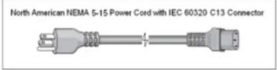
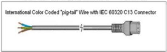
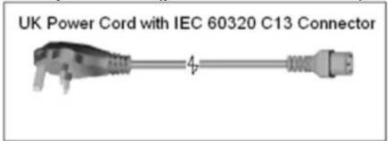
The power cord that is supplied with the PMM-2 is based upon the power cord selection in the PMM-2 style number. Depending on the country, the power cord can come with a NEMA 5-15 male connector, a CEE 7/7 Schuko two prong connector, come with International Color-Coded pig-tail wires (light blue, brown and green with yellow stripe) with the insulation jacket stripped ready for installation of the appropriate male connector, or the UK power cord, see the following example cord descriptions and associated part numbers.
North American power cord (part number 6828)
Continental Europe power cord (part number 90015-268)

The International Color Code power cord (part number 90015-269) is ready for wiring to the appropriate plug (depending on country). The following colors apply, Brown = Line, Blue = Neutral and Green/Yellow = Ground.
UK power cord (part number 90015-270)
3.3 Top panel communication ports and input terminals

Figure 2: Communication ports and input terminals
- USB interface terminals ① - there are two Type A and one Type B USB terminals available. The USB 2.0 Interface requires a Type B "downstream" connector and is primarily used as a communication and control port when used with Megger software. A USB cable is not provided with the test set or in the optional accessories. For computer control, an Ethernet cable is provided. However, should the user desire to use the USB port any standard USB A/B cable will work with the unit.
- IN/OUT Ethernet Ports ② are 10/100BaseTX ports. The IN port is the primary PC connection port. This port supports MDI/MDI-X auto cross over configuration, which means both standard and “crossover” Ethernet cables may be used. This port provides the optimal method for downloading files and updating the unit’s firmware as required. The PMM-2 comes standard with a crossover cable. The OUT port is for future use.
- Binary inputs 1 and 2 ③ –The binary inputs 1 and 2 will accept a voltage range of 1 to 300 VAC, or 1 to 250 VDC, or dry normally open/normally closed contacts. The binary input #1 voltage threshold is programmable from 1 to 150 V AC/DC, or a TTL fixed voltage level of 2.7 V. Binary input #2 has a TTL fixed voltage level of 2.7 V. These terminals are used with the digital timer to start and stop the timing operations.
- BNC clamp-on CT channel inputs CT1 to CT4 ④ - Four inputs are provided for use with clamp-on CTs to measure primary current with a low voltage output. An arrow on the current clamp indicates the direction of the load. See section 5.2.3 Clamp-on current and potential transformer operation for more details.

Maximum input voltage rating of CT1 to CT4 is 1 V.
- Current inputs I1 to I3 ⑤ - Three independent current inputs are provided. The correct polarity, for the phase angle measurement purposes, is indicated by the red terminal. These inputs are either rated for 60 A or 100 A depending on the style number ordered.
- Current input I4 ⑥ - The I4 current input is designed to measure up to 32 A continuous. Normally used to connect to measure the neutral current.
- Voltage inputs V1 to V4 ⑦ - The single AC/DC or polyphase voltages are connected to these terminals, as labelled. Used to measure voltages up to 1000 V phase to neutral.
3.4 Configuration of PMM-2 software
The PMM-2 software is the manual control and user interface for the unit. All manual entries will be made through the touch screen of the PMM-2, or the software installed on a PC. Before connecting power to the unit, make sure the PMM-2's POWER ON/OFF switch is in the OFF position (switch flush with the bezel). Plug the unit line cord into an appropriate power source, connect the safety ground terminal to an appropriate earth ground, and turn the POWER ON/OFF switch to ON (press the button in, the button ring will light up). The PMM-2 unit will go through its power up sequence, and in ±30 seconds the main startup screen will appear.

other
| Current (A) | Time (ms) | Voltage (V) | Time (ms) | | :--- | :--- | :--- | :--- | | 0.000 | 12.2865 | -0.02 | 0 | | 0.000 | -0.0002 | -0.04 | 0 | | 0.000 | 0.95 | -0.05 | 0 | | 0.000 | 1.49 | -0.02 | 0 | | 0.000 | -1.00 | -0.02 | 0 | | 0.000 | 342.46 | -0.02 | 0 | | 0.000 | 2.10 | -0.02 | 0 | | 0.000 | 180.02 | -0.02 | 0 | | 0.000 | 0.14 | -0.02 | 0 | The image contains two panels: the left panel is a table showing current (A) and voltage (V) for a three-phase system, while the right panel is a table showing timer (s) for each phase of the current in V and V_L-N series.Figure 3: Main startup screen
In the upper left-hand corner, is the unit connection button. When using the PMM-2 without a PC the connection will happen automatically and the user should not need to select this button for connection. When connecting the PMM-2 with a PC the user will need to launch the PMM-2 software and once launched a pop-up window will show the IP address, the serial number of the unit and the time since boot up (see Figure 3). Highlight the appropriate unit and select the "connect" button to establish connection with the PMM-2.

Figure 3: Main startup screen (PC)
3.4.1 Configuration
Pressing the Configuration button will allow the user to configure the PMM-2 hardware and PMM-2 software by displaying tabs for; System configuration, Phase settings display configurations, CT/PT settings configurations, and Chart color options for grid, voltage and current phasors and waveform traces, see figure 4.
3.4.1.1 Screen exit
To exit the Configuration screen and return to the previous screen press the green check button (you will see this same button on other screens).

Figure 4: System configuration screen
3.4.2 System configuration options
This section of the manual will describe the System, Phase, CT/PT, and Colors configurations in the PMM-2 software.
3.4.2.1 Virtual alphanumeric keyboard
The virtual alphanumeric keyboard will automatically appear in appropriate touch screen windows to allow the entry of ASCII text. This keyboard is used to enter names for user defined profiles, change the "neutral" channel name, timer inputs, file names. See the following sections for examples
3.4.2.2 Configuration profile options
Found in the system configuration settings section, the system profile defaults to "Factory Default." However, the user can customize the system settings profile and save a new profile by pressing the "Save As" button and giving it a name. Touch the line associated with the "Profile Name" and a virtual keyboard will appear, enter a name, and then press the enter key. In the PC version of the software the user will need to click in the "Profile Name" box, enter a name and then click the green check mark.

Figure 5: Enter new profile name
The system configuration settings profile can be updated or deleted by pressing the appropriate buttons.
3.4.2.3 Label settings
Found in the system configuration settings section; this button allows the user to set labels for each phase; ABC, RST, XYZ, or 123. Channel 4 defaults to N for neutral. However, the user can change the label by pressing on the "N" and an alphanumeric keyboard will appear for the user to enter a label and then press the enter key. In the PC version of the software the user will need to click in the "Channel 4" box and enter a name or a label.

Figure 6: Changing channel 4 name with the alphanumeric keyboard
NOTE: To save the new labels, press the "Save As" in the profile window and give the new profile a name.
3.4.2.3.1 Voltage character
The voltage character is used to define and label the voltage channels and can be either V or U. Press the appropriate button to change to the preferred character. Be sure to press the "Save As" in the profile window or "Save" to update the current profile to save the changes.
3.4.2.4 Global settings
In the "Global Settings" window the user will find the option to select a specific language, setting the internal System Date and Time, and View System Information.
3.4.2.4.1 Language
Found in general settings; this button allows the user to select the desired displayed language (English, French, Spanish and German). The factory default is English but may be changed to Spanish or German.
3.4.2.4.2 Set system date and time
Press the Internal button to reset the Date and Time in the PMM-2 software. This information is critical for saving recorded values in the unit internal file manager.
3.4.2.4.3 System info (information screen)
The "System Info" is found in "Global settings." Pressing the "System Info" button will display the unit serial number, model number, IP address, software and firmware versions, bootloader version, and versions of DSP, voltage (VPMM) and current (IPMM) circuit boards.

Figure 7: System info screen
NOTE: This information is useful when calling Megger for service or technical support related issues. This is also the screen that you use to update the PMM-2 system, see section 6.4 for instructions.
3.4.2.5 Screen dimming
In this section of the "System Configuration" screen the user can set an idle time in minutes for when the unit is on battery or mains power. To save battery power and extend the operating time, the screen will automatically dim based upon the user defined idle time setting. In the "Brightness (0 - 100)" the brightness of the screen can be set based on a percentage.
3.4.2.6 Sample settings
The "Sampled Settings" box contains the "Fundamental Frequency" button, the "Waveform Capture Rate" button and the "Pre-trigger Samples" button.
3.4.2.6.1 Fundamental frequency
In the default "Detected" setting, the PMM-2 will measure and determine the input line frequency and automatically set the default fundamental frequency to the measured line frequency. To measure harmonics when using the battery, without the mains line cord connected, the user will need to select the fundamental frequency of the sources you are measuring. Choices are 50 Hz, 60 Hz, and 400 Hz.
3.4.2.6.2 Waveform capture rate
In the default "7.2 kHz" setting, the PMM-2 will sample the waveforms at a rate of 7.2 kHz (144 samples per second at 50 Hz or 120 samples per second at 60 Hz). When making a recording of data, the slower the sampling rate the more data can be captured and saved to internal memory. The higher sampling rates may be needed for higher resolution of the recorded data. Other sampling rates that are available are 3.6, 4.8, 9.6, 14.4 and 28.8 kHz. To measure harmonics, see section 4.3.9.15, it is recommended to use the 28.8 kHz sampling rate.
3.4.2.6.3 Pre-trigger samples
The "Pre-trigger Samples" is defaulted to 500 and will be the time used to record/capture data before a trigger condition is reached. As an example: The PPM-2 samples at 28.8kHz and with the default value of 500 the time for the pre-trigger will be: 1 / 28800*500 = 17.36 ms
3.4.2.7 Diagnostic logging settings
In the "Diagnostic Logging Settings" window the logging function is OFF by default. Select the "Enable Logging" button to log commands sent to the PMM-2 from the PMM-2 software. This information can be useful to the Megger technical support group when troubleshooting. The "Clear Logs" button is used to clear existing log files and the "Copy Logs" will copy recorded log files to a USB thumb drive when inserted into the PMM-2. Logged commands does consume a small amount of the internal memory, therefore, users may opt to leave the logging OFF if more memory is required such as in recording data, see section 4.3.8 recorder feature.
3.4.3 Phase angle configuration screen
When using the "Polar Plot" display option, see section 4.3.9.12, the measured phase angles can be displayed in a variety of combinations, depending on what the user wants to see. Selecting the "Phasor" button in the configuration screen will provide the following figure.

Figure 8: Phase Angle Configuration Setting screen
The phase angle designations can be set to 0-360° Lead, 0-360° Lag, or ±180 degrees. The rotation can also be set to either counterclockwise (CCW) or clockwise (CW) rotation. The factory default is 360° Lag, CCW. The X-Axis 0° defaults to the right. Pressing the left button will move the 0° over to the left side. The buttons in the bottom are used to select what values will be measured and displayed, such as measure and display phase to neutral (L-N) voltages or display phase to phase (L-L), or measure and display phase to phase (L-L).
3.4.4 CT/PT ratios
The PMM-2 software "Configuration Screen" includes the CT/PT ratios setting button.

Figure 9: CT/PT ratios input selection screen
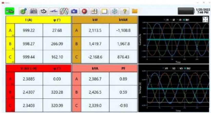
Select either ANSI or IEC graphics. Enter the appropriate voltage and/or current primary and secondary values. If you want to view the primary values based upon the CT and PT ratios entered, press primary and upon returning to the main screen primary values such as kV, kA, kW and/or kVAR will be displayed.
other
| Category | Value 1 | Value 2 | |---|---|---| | A | 999.22 | 27.68 | | B | 998.27 | 266.09 | | C | 999.44 | 162.10 | | Current (N) | -1,108.8 | -1,108.8 | | Voltage (V) | 2,386.7 | 0.89 | | Time | -0.93 | -0.93 |Figure 10: Primary values displayed with split screen waveforms
Note the primary values displayed for the voltage is in kV.
3.4.6 Colors options
Press this button to adjust the colors of the voltage and current waveform traces and vectors, background, labels, and more.
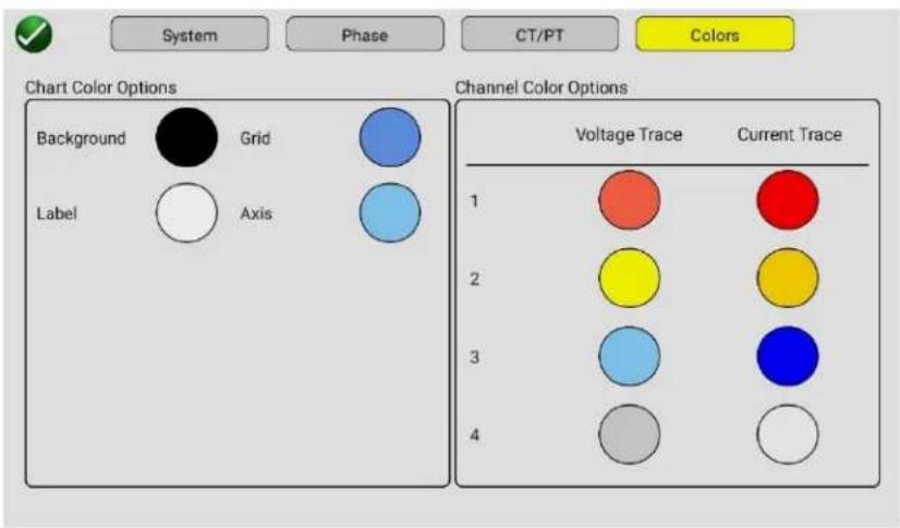
Figure 11: Color options
4.0 General operating instructions
4.1 Safety considerations

DANGER: The measuring terminals of this instrument can be connected to lethal voltages and dous current circuits. Professional organizations using this instrument will normally have safety dures covering such installations and users will be trained to follow them. Not withstanding conditions, certain precautions should be followed when using this instrument.
- The chassis ground connection should always be firmly attached to the system ground bus, even when an AC line cord is used.
- Connections should be established to the potential and current terminals before the measuring circuit is energized.
- The use of potential leads containing high rupture fuses is recommended in high KVA circuits, see optional test leads.
- All current terminals should be tightly fastened, to avoid dangerous terminal voltages and preclude ohmic heating at high current.
4.2 Set up of PMM-2
4.2.1 Unpack system
Unpack the unit and check the instrument and accessories for evidence of any shipping damage. If there is any visual damage, immediately notify the freight carrier to make a damage claim and notify Megger of the damage. If no damage, save the shipping box and packing material for reuse, such as returning the unit for calibration. If being returned for calibration or service, see section 10.2 return procedure.
4.2.2 Initial startup

DANGER: THIS INSTRUMENT IS DESIGNED TO BE USED TO MEASURE POTENTIALLY LETHAL VOLTAGE AND CURRENT. ALL SAFETY PROCEDURES AND PRECAUTIONS MUST BE FOLLOWED WHEN OPERATING ON LINE WITH LETHAL VOLTAGES OF HIGH CAPACITY!
- Before connecting power to the unit, make sure the unit POWER ON/OFF switch is in the OFF position (top of the ON/OFF switch is flush with the bezel).
- Plug the unit line cord into an appropriate power source, connect the safety ground to an appropriate earth ground, and turn the POWER ON/OFF switch to ON (press the button in, the button bezel ring will light up). The PMM-2 unit will go through its power up sequence, in less than 30 seconds and the main startup screen will appear, see section 4.3.
4.2.3 Battery
After powering up the PMM-2 you will note in the upper right corner of the touch screen the battery charge icon. It will indicate the level of charge on the internal battery. NOTE: Always ensure that the battery is properly and fully charged before using the instrument in the battery operation mode.
4.2.3.1 Battery charging
NOTE: If the PMM-2 has been in storage for more than a week, it is very important that the unit be given a full charge before being used in the battery operation mode.
The internal charger will automatically charge the battery when the line power is applied to the instrument, and the unit is turned on. The instrument can be used while the battery is being charged.
The BATTERY charge icon also acts as low-battery indicator. The icon will change color or flash, once the battery charge drops below 25%.
In order to prolong the life of the battery and ensure optimum performance, the following procedure should be observed:
- Charge the battery overnight after using the instrument. The battery is protected against overcharging
- Fully charge the unit prior to storage. Store the unit in a cool dry environment. While in storage, fully charge the instrument at least once a month.
- If the battery condition has deteriorated to a point where it will not accept a charge, the battery will need to be replaced, see Service and Repair.

Spent batteries are classified as Industrial Batteries. Do not dispose of the battery general waste. For disposal in the UK contact Megger Ltd. in Dover. For disposal of batteries EU contact your local distributor. For disposal in the USA check with your local recycling
4.3 Main startup screen
This section of the manual describes each of the items shown in the following figure.
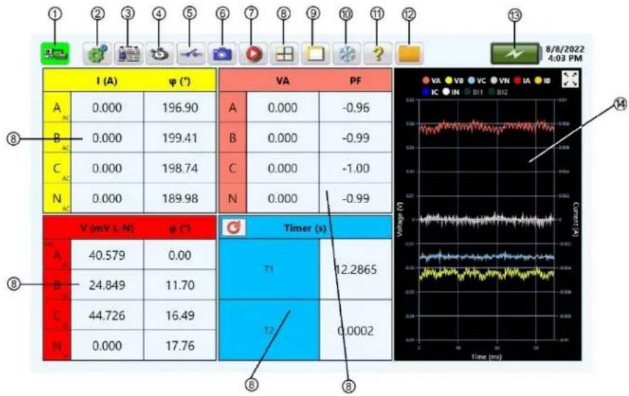
other
| Panel | I (A) | φ (°) | VA | PF | |---|---|---|---|---| | A | 0.000 | 196.90 | A | 0.000 | | B | 0.000 | 199.41 | B | 0.000 | | C | 0.000 | 198.74 | C | 0.000 | | N | 0.000 | 189.98 | N | 0.000 | | Total V (mV L N) | 40.579 | 0.00 | Timer (s) | 12.2865 | | Total B | 24.849 | 11.70 | T1 | 0.0002 | | Total C | 44.726 | 16.49 | T2 | 0.0002 | The chart includes a Time-resolved waveform graph on the right, with 'Current (A)' as the Y-axis label and 'Time (ms)' as the X-axis label. The top row is labeled '8/8/2022 4:03 PM'.Figure 12: Main startup screen identifications
4.3.1 ① Connection button

The PMM-2 software will auto-connect to the PMM-2 instrument. If for any reason you should lose connection between the software and the PMM-2 press or click on the button and the touch screen will auto connect to the PMM-2.
4.3.2 ② The configuration button

Press this button to go to the PMM-2 software configuration screen. See Section 3.4.1 Configuration for more information of the configuration screen.
4.3.3 ③ Report options button

The "Report Options" button will take you to the custom reports in this screen. By default, there are different report formats built in, or you can customize your own report. Should the user have any specific/custom reports that they would want to use, please contact your local Megger representative for assistance in creating such a report. The report may be saved in csv. and Pdbxml format for later export to a PC.
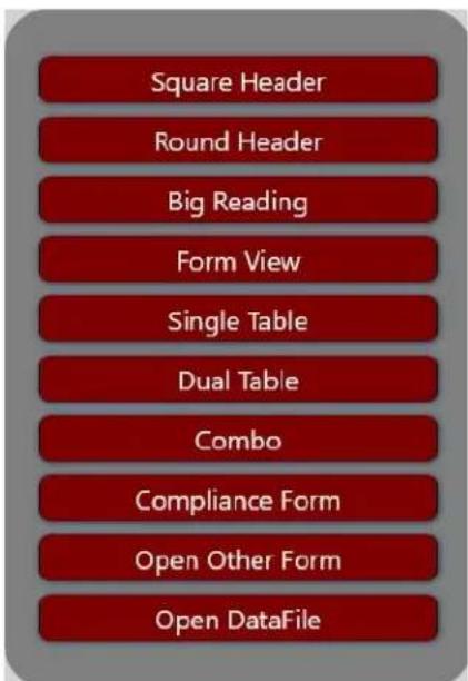
Figure 13: Reports options – customs form available in the software
4.3.4 ④ Timer configuration button

The PMM-2 is equipped with an internal timer, primarily intended for performing timing tests on protective relays and circuit breakers. The timer is equipped with a sensing circuitry that responds to a change of state. This change may be a contact opening or closing, or the initial application of an AC or DC voltage, removal of an AC or DC voltage, see 4.3.5 using the binary input configuration button. It may also be programmed to respond when sensing the application or removal of a current or voltage applied to the measuring terminals. The Binary Input terminals are isolated from the chassis ground and are independent of signal polarity.

APPLICATION NOTE: When using the binary inputs in parallel with another test set, it is very important that polarity be observed (red and black binding post). If the binding posts are cross connected the timer will not function correctly.

Figure 14: Timer configuration screen
4.3.4.1 Timer configuration
Using the timer configuration screen the user can select the units of time measurement in seconds, milliseconds, or cycles by pressing the "Units" button; configure the number of timing tests by selecting the "Enable" button for T1 to T10 and "Name" each test; set "Start" and "Stop" "Condition" and "Channel" and configure the timing "Mode".
The user can conduct multiple timing tests such as a trip and reclose timing test. Up to 10 timers can be enabled by pressing the "Enable" button, with selection changing the color of the switch to yellow. To rename the timer click in the "Name" box and the virtual keyboard will be provided to enter a name. The name is limited to 19 displayed characters, which will be displayed in the main screen and captured using snapshot for record keeping.
4.3.4.1.2 Start/stop condition
The Start and Stop Conditions are programmable.

flowchart
graph TD
    A["Select a condition"] --> B["Binary Input High/Closed"]
    A --> C["Binary Input Low/Open"]
    A --> D["Analog Non-Zero"]
    A --> E["Analog Zero"]
Figure 15: Timer start/stop conditions menu
The following are descriptions of each condition.
Binary input high/closed: When using the binary inputs 1 and/or 2 to start and/or stop the timer, use this selection for dry contacts closing or voltage applied conditions, see 4.3.5.
Binary input low/open: When using the binary inputs 1 and/or 2 to start and/or stop the timer, use this selection for dry contacts opening or voltage removed conditions, see 4.3.5.
Analog non-zero: Select this condition to start and/or stop the timer with the application of a voltage or current to any of the measuring inputs, see channel selection below.
Analog zero: Select this condition to start and/or stop the timer with the removal of a voltage or current to any of the measuring inputs, see channel selection below.
4.3.4.1.2.1 Channel selection
When using applied or removed measured analog values to start and/or stop the timer the user will need to specify which channel is to be used to start and/or stop the timer.
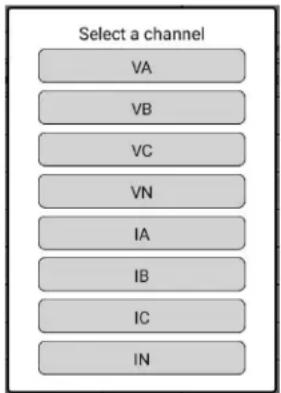
flowchart
graph TD
    A["Select a channel"] --> B["VA"]
    A --> C["VB"]
    A --> D["VC"]
    A --> E["VN"]
    A --> F["IA"]
    A --> G["IB"]
    A --> H["IC"]
    A --> I["IN"]
Figure 16: Channel select for analog start/stop
APPLICATION NOTE: To do a timing test on an overcurrent relay you may want to start the timer when the current is applied to the relay. Therefore, set the timer to Start with Analog Non-Zero, and series the current through the appropriate channel input to the relay under test. When current is applied, the measured value will appear in the appropriate window and the timer will start. For a Dropout timing test select Start Analog Zero. When the current is removed the timer will start. Use Binary Input #2 to monitor relay trip contacts to stop the timer.
4.3.4.1.3 Mode selection

flowchart
graph TD
    A["Select a mode"] --> B["One-Shot"]
    A --> C["Accumulate"]
    A --> D["Sequence"]
Figure 17: Timer mode selection screen
The one-shot mode is for a single timing test, where only one timing result is required.
The accumulate mode is used to time a single contact from the time it closes/opens until it opens/closes again. The total time will include any additional change of states, such as contact bounce.
The reclosing mode is used to time a recloser open/close to lock-out sequence.
4.3.5 ⑤ Binary input configuration button

There are two binary inputs, #1 and #2. Normally they are used in conjunction with the timer. However, they can also be used to conduct continuity checks, monitor dry contacts such as in doing a minimum pickup/dropout test on an electromechanical relay, or monitor for presence/application of AC/DC voltages. Press this button to configure binary inputs 1 and 2.

| Input | Type | Threshold Volts | Trigger | Debounce (ms) | Sound |
| BI #1 | 10.00 | 2.00 | |||
| BI #2 | 10.00 | 2.00 |
Figure 18: Binary input configuration screen
Binary inputs #1 and #2 default to sensing for closing or opening of dry relay contacts, as displayed by the icon in the input type window. To sense voltage, press the input type contact icon and it changes showing a AC/DC voltage symbol. In voltage sensing mode, the unit is sensing the application or removal of an AC or DC voltage. A programmable voltage threshold is available on binary input #1, with a programmable range from 5 to 150 V AC/DC.
APPLICATION NOTE: A higher threshold voltage helps to eliminate false triggers due to a noisy test environment. Binary input #1 can also be programmed to sense a TTL voltage by pressing the AC/DC type button again and it will show the icon for a TTL voltage sensing of 2.7 V.
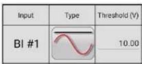
Figure 19: Programmable voltage threshold setting
The programmable threshold voltage default value is 10 V. Press or click in the threshold window and enter the desired voltage threshold using the virtual keyboard. Binary input #2 has a fixed TTL voltage setting of 2.7 V. If no Trigger is selected (the default setting), and the Horn is set to ON, the binary inputs will act like a monitor circuit, sounding the horn when the input condition is true, depending on the type setting. Note that if the trigger is enabled it will freeze the screen values when the input condition is true, see freeze section 4.3.11 for more details.
APPLICATION NOTE: When the contacts close or voltage is applied, if the horn Sound button selected to ON, the horn will sound. If the Horn does not sound, press the timer reset button. If a normally closed contact opens or voltage is removed with horn on, the horn will go off.

The debounce time is set in milliseconds. This feature is normally used when testing electromechanical relays with contacts that bounce. The trip contacts must stay closed for the debounce time for the input condition to be true. If the input condition reverses in less than the set debounce time the timer will continue to run. Once the input condition is true then the time test will conclude and/or the horn will sound. The trip time displayed will be the total test time less the debounce time.
4.3.5.1 Trigger configuration button
The trigger configuration is used in conjunction with the screen freeze, see section 4.3.11. Pressing the trigger configuration button will provide the user with the following two options.
The first option is the low to high ☐, which is defined as dry contacts move from open to close or AC/DC voltage applied, depending on the binary input type selected. Pressing the button again will select the high to low ☐, which is defined as dry contacts move from closed to open or AC/DC voltage removed, again depending on the binary input type selected. When the binary input senses the change in state it will freeze the display screen. The user can either un-freeze the displayed values by pressing the freeze button or use the snapshot to save a picture of the display screen, save the displayed screen data, or both, see section 4.3.6 snapshot. Press the button again to deselect the trigger.
4.3.6 ⑥ Snapshot button

Pressing this button, the user can capture and save either an image of the displayed values like a screenshot, save the data only, or save both.

Figure 20: Snapshot options screen
Press on the file name entry line and the virtual keyboard will appear. Save either the displayed image by pressing the Image radio button, and/or press on the data radio button to save the displayed data. Images and data are saved to internal memory. To review images and/or data, press on the file folder button in the tool bar.
4.3.8 ⑦ Record button

Press this button to use the recording feature of the PMM-2. For normal single-phase or three-phase measurement the instrument can be configured so that the screen data is recorded into non-volatile memory in the PMM-2 on a pre-programmed time interval over a programmable duration, see section 5.4 time data recording. To review recorded data, press on the file folder button in the tool bar.
4.3.9 ⑧ Select panels and charts to display button

The user can customize the displayed values shown in the left side of the display and change the chart display screen in the top right hand corner, see item ⑭. Press this button to select what combination of values or charts are displayed. The following are descriptions of each available panel.

flowchart
graph LR
    A["Current/Frequency"] --> B["Current"]
    C["Voltage/Frequency"] --> D["Voltage"]
    E["Frequency"] --> F["Power"]
    G["Current Min/Max"] --> H["Voltage Min/Max"]
    I["KVA/PF"] --> J["Timer"]
Figure 21: Select panels to display screen
4.3.9.1 Enable current/frequency panel
When enabled the selected current(s) and their respective phase angles and frequency for each phase will be displayed in the top left side of the display. When enabled the switch changes color from grey to yellow.
| I (A) | ( ^ ) | Hz | |
| A | 0.800 | 29.82 | 60.000 |
| B | 0.801 | 149.83 | 60.000 |
| C | 0.800 | 269.84 | 60.000 |
| N | 0.000 | 34.90 | 0.000 |
Figure 22: Enabled current/frequency panel
4.3.9.2 Enable current panel
When enabled the selected current(s) and their respective phase angles will be displayed in the top left side of the display. When enabled the switch changes color from grey to yellow.
| I (A) | φ (°) | |
| A AC | 0.800 | 29.82 |
| B AC | 0.801 | 149.84 |
| C AC | 0.800 | 269.84 |
| N AC | 0.000 | 29.04 |
Figure 23: Enabled current panel
4.3.9.3 Enable voltage/frequency panel
When enabled the selected voltages and their respective phase angles and frequency for each phase will be displayed in the bottom left side of the display. When enabled the switch changes color from grey to yellow.
| V (VLN) | ( ^ ) | Hz | |
| A | 112.04 | 0.00 | 60.000 |
| B | 112.06 | 119.99 | 60.000 |
| C | 112.07 | 240.04 | 60.000 |
| N | 0.000 | 144.32 | 0.000 |
Figure 24: Enabled voltage/frequency panel
4.3.9.4 Enable voltage panel
When enabled the selected voltages and their respective phase angles will be displayed in the bottom left side of the display. When enabled the switch changes color from grey to yellow.
| V (V, L, N) | ( ^ ) | |
| A | 111.97 | 0.00 |
| B | 112.12 | 120.01 |
| C | 112.09 | 240.00 |
| N | 0.000 | 98.08 |
Figure 25: Enabled voltage panel
4.3.9.5 Enable frequency panel
When enabled the frequency for each phase of voltage and current will be displayed in the top right side of the numerical display. When enabled the switch changes color from grey to yellow.
| I (Hz) | V (Hz) | |
| A | 60.000 | 60.000 |
| B | 60.000 | 60.000 |
| C | 60.000 | 60.000 |
| N | 0.000 | 0.000 |
Figure 26: Enabled frequency panel
4.3.9.6 Enable power panel
When enabled Watts and VARs will be displayed either in the top or bottom right side of the numerical display, depending on other panel configurations. Values may be mW, W, kW depending on the values of the voltages and currents. When enabled the switch changes color from grey to yellow.
| W | Var | |
| A | 77.674 | 44.580 |
| B | 77.850 | 44.669 |
| C | 77.792 | 44.671 |
| N | 0.000 | 0.000 |
Figure 27: Enabled Watts and VARs
NOTE: In order to enable the power panel, either the frequency panel or VA/PF panel must be disabled. To view frequency with the power and VA/PF panels, enable the current/frequency and voltage/frequency panels.
4.3.9.7 Enable VA/PF panel
When enabled the VA and power factor values will normally be displayed in the bottom right side of the numerical display, depending on other panel configurations. Values may be mVA, VA, kVA depending on the values of the voltages and currents. When enabled the switch changes color from grey to yellow.
| VA | PF | |
| A | 89.588 | 0.87 |
| B | 89.730 | 0.87 |
| C | 89.695 | 0.87 |
| N | 0.000 | 0.24 |
Figure 28: Enabled VA/PF (power factor) panel
4.3.9.8 Enable timer panel
When enabled the timer will be displayed in the bottom right side of the numerical display. The number of timer windows depends on the number of timers set in the timer configuration screen. When enabled the switch changes color from grey to yellow.
| Timer (s) | |
| T1 | 12.2883 |
| T2 | 0.0001 |
Figure 29: Enabled timer panel
NOTE: In order to enable the timer panel display, either the frequency panel, power panel or the VA/PF panel must be disabled. To view frequency with the timer and power (or VA/PF) panels enabled, enable the current/frequency and voltage/frequency panels.

APPLICATION NOTE: Depending on which panels are enabled/disabled, the user may see some unusual numerical displays, i.e., two voltage panels displayed (one with frequency and one without).
The following are descriptions of each available chart.

flowchart
graph TD
    A["Select Chart Mode"] --> B["Combined Waveform"]
    A --> C["Polar"]
    A --> D["Split Waveform"]
    A --> E["Combined Waveform With Binary"]
    A --> F["Polar With Binary"]
    A --> G["Harmonics"]
    H["Charts Off"] --> A
Figure 30: Select chart mode screen
4.3.9.9 Charts off
Selecting this mode will turn all charts off on the main display.
| T(A) | W(T) | VA | Pf | ||
| A | 0.800 | 29.86 | A | 89.561 | 0.87 |
| B | 0.801 | 149.88 | B | 89.750 | 0.87 |
| C | 0.801 | 269.88 | C | 89.815 | 0.87 |
| N | 0.000 | 41.19 | N | 0.000 | 0.25 |
| T(30,40) | W(7) | Tier (a) | |||
| 111.98 | 0.00 | 8.4540 | |||
| 112.08 | 126.02 | ||||
| 112.15 | 240.03 | 0.0016 | |||
| 0.000 | 116.68 | ||||
Figure 31: Charts off screen
APPLICATION NOTE: Pressing the display enlarge button in the top right corner of the display screen will enlarge the selected display screen for enhanced viewing. It could be used in conjunction with the freeze screen button to capture waveforms for viewing. Press the enlarged display screen to reduce the size.
4.3.9.10 Combined waveform mode
Selecting this mode will provide the combination of both the metered voltage and current waveforms, normally used to monitor combined three phase waveforms (see main startup screen item 14).
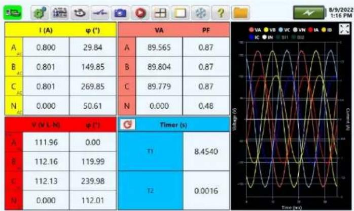
Figure 32: Combined waveform screen
APPLICATION NOTE: If measuring low current i.e., mA, it is recommended to select the split waveform mode, since the low current may not be visible in the combined waveform mode due to scaling.
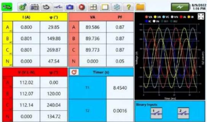
4.3.9.11 Combined waveform with binary mode
Selecting this mode will provide the combination of both the metered voltage and current waveforms, normally used to monitor combined three phase waveforms (see Main Startup Screen item 14). It also includes the state of Binary Inputs #1 and #2, indicated by the thick aqua colored lines in the chart and the binary inputs panel at the bottom of the chart indicating the current state of the binary.
other
A B C N I (A) VA PF A B C N V (V, L, N) Timer (s) T1 8.4540 T2 0.0016 Binary Inputs 1 2 3 4 5 6 7 8 9 10 11 12 13 14 15 16 17 18 19 20 21 22 23 24 25 26 27 28 29 30 31 32 33 34 35 36 37 38 39 40 41 42 43 44 45 46 47 48 49 50 51 52 53 54 55 56 57 58 59 60 61 62 63 64 65 66 67 68 69 70 71 72 73 74 75 76 77 78 79 80 81 82 83 84 85 86 87 88 89 90 91 92 93 94 95 96 97 98 99 100Figure 33: Combined waveform with binary screen
4.3.9.12 Polar mode
Depending on the phase angle configuration, see section 3.4.3 phase angle configuration screen settings, pressing on this button will provide a polar plot of the voltage and current vectors

radar
| Category | I (A) | φ (°) | VA | PF | |---|---|---|---|---| | A | 0.800 | 29.81 | A | 89.604 | | B | 0.801 | 149.84 | B | 89.767 | | C | 0.801 | 269.84 | C | 89.722 | | N | 0.000 | 44.29 | N | 0.000 | | Total | 112.02 | 0.00 | T1 | 8.4540 | | Total | 112.13 | 119.95 | T2 | 0.0016 | | Total | 112.08 | 239.99 | Total | 0.0016 | | Total | 0.000 | 181.30 | Total | 0.0016 |Figure 34: Polar plot of 3-phase voltage and current vectors
4.3.9.13 Polar mode with binary
Depending on the phase angle configuration, see section 3.4.3 phase angle configuration screen settings, pressing on this button will provide a polar plot of the voltage and current vectors. This mode also includes the state of Binary Inputs #1 and #2, indicated by the thick aqua colored lines in the chart and the binary inputs panel at the bottom of the chart indicating the current state of the binary.
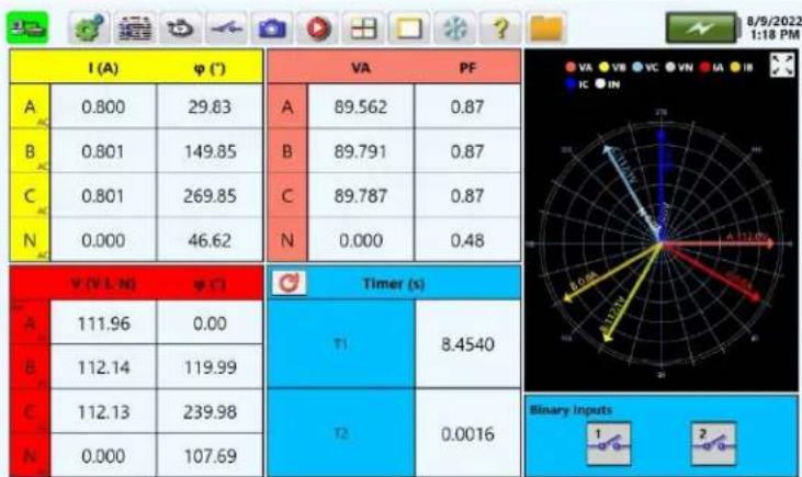
Figure 35: Polar plot of 3-phase voltage and current vectors and binary inputs
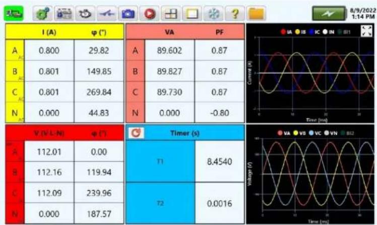
4.3.9.14 Split waveform mode
Press this button to display voltage and current waveforms in the split screen mode.
other
| Category | Value | |---|---| | A | 0.800 | | B | 0.801 | | C | 0.801 | | N | 0.000 | | Time (ms) | Label | | :--- | :--- | | 0 | 0.000 | | 1 | 269.84 | | 2 | 44.83 | | Voltage (V) | Label | | :--- | :--- | | 0 | 89.602 | | 1 | 89.827 | | 2 | 89.730 | | 3 | -0.80 | | 4 | 8.4540 | | 5 | 0.0016 | | Time (ms) | Label | |---|---| | 0 | 112.01 | | 1 | 112.16 | | 2 | 112.09 | | 3 | 187.57 | The image contains two panels: the left panel is a table showing current (A) and phase (φ, °) for different components, while the right panel is a table showing a time-resolved waveform with 'Current (A)' and 'Time (ms)' as the x-axis values.Figure 36: Split waveform screen
As can be seen the voltages are in the bottom half, and the currents are in the top half of the display screen.
4.3.9.15 Harmonics mode
Pressing this button will provide a screen with the fundamental amplitudes above the displayed harmonic spectrum, and the DC and AC amplitudes for each phase and harmonic displayed on the left side of the display.

bar
| Frequency | Voltage (V) | Phase A (VA) | Phase B (VB) | Phase C (VC) | Phase N (VN) | |---|---|---|---|---|---| | 0 | 111.95 | 111.95 | 112.12 | 112.15 | 0.000 | | 1 | 0.800 | 0.800 | 0.801 | 0.801 | 0.000 | | 2 | 0.00 | 0.00 | 0.00 | 0.00 | 0.00 | | 3 | 0.00 | 0.00 | 0.00 | 0.00 | 0.00 | | 4 | 0.00 | 0.00 | 0.00 | 0.00 | 0.00 | | 5 | 0.00 | 0.00 | 0.00 | 0.00 | 0.00 | | 6 | 0.00 | 0.00 | 0.00 | 0.00 | 0.00 | | 7 | 0.00 | 0.00 | 0.00 | 0.00 | 0.00 | | 8 | 0.02 | 0.02 | 0.05 | 0.17 | 0.26 | | 9 | 0.15 | 0.15 | 0.11 | 0.14 | 3.0 | | 10 | 0.66 | 666 | 666 | 666 | 666 | | 11 | 726 | 726 | 726 | 726 | 726 | | 12 | 786 | 786 | 786 | 786 | 786 | | 13 | 846 | 846 | 846 | 846 | 846 | | 14 | 966 | 966 | 966 | 966 | 966 | | 15 | 1236 | 1236 | 1236 | 1236 | 1236 | | 16 | 1524 | 1524 | 1524 | 1524 | 1524 | | 17 | 1822 | 1822 | 1822 | 1822 | 1822 | | 18 | 2128 | 2128 | 2128 | 2128 | 2128 | | 19 | 2436 | 2436 | 2436 | 2436 | 2436 | | ... (repeated) | ... (repeated) | ... (repeated) | ... (repeated) | ... (repeated) | ... (repeated) | The image contains two charts: a bar chart for Voltage (V) and a bar chart for Harmonic Order (Harmonic Order). The values in the 'Current' column are explicitly labeled on the bars.Figure 37: Harmonics display screen
Using the touch screen, slide your finger up and down the columns of data to view harmonic data up to the 50^th harmonic.
4.3.10 ⑨ Voltage and current general settings options

The user can configure the voltage and current channels, including the neutrals, and select phase reference.
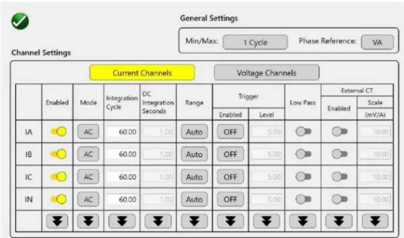
Figure 38: Voltage and current general settings screen
APPLICATION NOTE: Pressing the down arrow button at the bottom of each column will change all of the channels to the same setting change. In other words, the user only needs to change one value and press the down arrow button to change all of the other channels to the same setting.
4.3.10.1 Voltage general settings options
4.3.10.1.1 Voltage channel enable/disable switch
Default setting is enabled indicated by the yellow button. To disable the channel, touch the left side of the switch slot and it will change color to indicate that the channel is disabled.
4.3.10.1.2 Voltage channel mode options
The default setting is AC. Touch the AC button, and a list of mode options will be provided.

flowchart
graph TD
    A["Select a mode"] --> B["AC"]
    A --> C["DC"]
    A --> D["RMS"]
    A --> E["AVG"]
Figure 39: Voltage channel modes
AC mode – The selected channel is set to measure AC voltage. DC mode- The selected channel is set to measure DC voltage. RMS – The selected channel is set to measure RMS voltage values. AVG – The selected channel is set to measure AVG voltage values.
APPLICATION NOTE: To determine transformer loss requires a correction factor using the AVG and RMS value of the voltage applied to the transformer.
4.3.10.1.3 Voltage channel integration cycles
Integration time is the calculated value of the voltage over a period of time. The default setting is 60 cycles, which ensures an accurate displayed value. The shortest integration time is 1 cycle.
4.3.10.1.4 Voltage channel integration seconds
Selection of the DC mode for the channel will provide access to the DC integration time setting. Integration time is the calculated value of the DC voltage over a period of time. The default setting is 1.00 second, which ensures an accurate displayed value. The shortest DC integration time is 0.10 second.
4.3.10.1.5 Voltage channel range options
The voltage channel has several ranges available. The default setting is auto, for auto-range, where the range change is done automatically based upon the measured values over the integration time setting.

Figure 40: Voltage ranges
4.3.10.1.6 Voltage channel trigger setting options
The trigger setting options are associated with the recorder feature. When the recorder feature is activated, the recorder will start based upon the trigger level entered in volts and whether the enabled level is > greater than the level entered or < less than the level entered. The default Level is 0.000 V, with the enabled set to > greater than. Therefore, if voltage is present on the input terminals and the recorder is activated, it will start immediately, or once voltage is sensed on the inputs it will start recording.
4.3.10.1.7 Voltage channel low pass filter
To enable the low pass filter for the voltage channels, move the selector switch to the right. It will change color indicating that the low pass filter is enabled. The low pass filter is used to attenuate noisy or transient signals above the 50^th harmonic of 60 Hz, or 3 kHz. This may provide greater accuracy of the measured voltage.
4.3.10.1.8 Voltage channel external CT settings
When using external clamp-on CTs with banana connectors on V1 to V4, the user will need to enable the external CT for the selected channel(s) by moving the selector switch to the right. It will change color indicating that the external CT has been enabled for the selected channels V1 to V4. The user will then need to enter the scale factor for the external clamp-on CT. The default value is 10.00 mV/A. When the voltage channels are used to measure current via the external CTs the voltage panel will change to a current panel in the home screen.
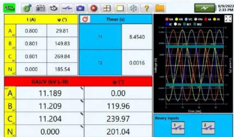
Figure 41: Voltage channels used to measure current via external CTs
NOTE: When using external CTs a clamp on CT icon will appear in the upper right hand corner of the specific channel.
4.3.10.2 Current general settings options

Figure 42: Current channels configuration screen
4.3.10.2.1 Current channel enable/disable switch
Default setting is enabled indicated by the yellow button. To disable the channel, touch the left side of the switch slot and it will change color to indicate that the channel is disabled.
4.3.10.2.2 Current channel mode options
The default setting is AC. Touch the AC button, and a list of mode options will be provided, see the following figure and descriptions.

flowchart
graph TD
    A["Select a mode"] --> B["AC"]
    A --> C["DC"]
    A --> D["RMS"]
    A --> E["AVG"]
Figure 43: Current channel modes
AC mode – The selected channel is set to measure AC current. DC mode- The selected channel is set to measure DC current. RMS – The selected channel is set to measure RMS current values. AVG – The selected channel is set to measure AVG current values.
4.3.10.2.3 Current channel integration cycles
Integration time is the calculated value of the current over a period of time. The default setting is 60 cycles, which ensures an accurate displayed value. The shortest integration time is 1 cycle.
4.3.10.2.4 Current channel DC integration seconds
Selection of the DC mode for the channel will provide access to the DC integration time setting. Integration time is the calculated value of the DC voltage over a period of time. The default setting is 1.00 second, which ensures an accurate displayed value. The shortest DC integration time is 0.10 second.
4.3.10.2.5 Current channel range options
The current channel has several ranges available. The default setting is auto, for auto-range, where the range change is done automatically based upon the measured values over the integration time setting.
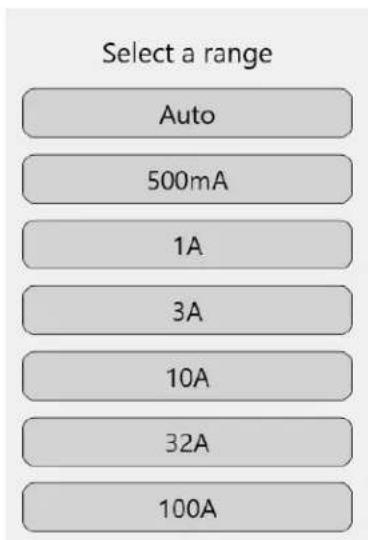
Figure 44: Current ranges
4.3.10.2.6 Current channel trigger setting options
The trigger setting options are associated with the recorder feature. When the recorder feature is activated, the recorder will start based upon the trigger level entered in A and whether the enabled level is > greater than the level entered or < less than the level entered. The default level is 5.00 A, with the enabled set to > greater than. Therefore, if a current of 5 A or greater is present on the input terminals and the recorder is activated, it will start immediately, or once current is sensed on the inputs it will start recording.
4.3.10.2.7 Current channel low pass filter
To enable the low pass filter for the current channels, move the selector switch to the right. It will change color indicating that the low pass filter is enabled. The low pass filter is used to attenuate noisy or transient signals above the 50^th harmonic of 60 Hz, or 3 kHz. This may provide greater accuracy of the measured current.
4.3.10.2.8 Current channel external CT settings
When using external clamp-on CTs with the BNC connectors CT1 to CT4, the user will need to enable the external CT for the selected channel(s) by moving the selector switch to the right. It will change color indicating that the external CT has been enabled for the selected channels CT1 to CT4. The user will then need to enter the scale factor for the external clamp-on CT. The default value is 10.00 mV/A.

Maximum input voltage rating of CT1 to CT4 is 1 V
4.3.10.3 Phase reference
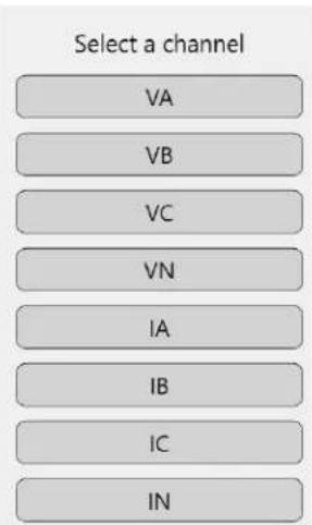
Whether single phase, or three phase, the PMM-2 can measure the phase angles between all metered values of voltage and/or current. It is customary to set the phase reference to phase A (V1) voltage input. However, the user can change the reference to any metered input. Press the phase reference button and the following list of channels will be provided.
flowchart
graph TD
    A["VA"] --> B["VB"]
    B --> C["VC"]
    C --> D["VN"]
    D --> E["IA"]
    E --> F["IB"]
    F --> G["IC"]
    G --> H["IN"]
Figure 45: Phase reference selection list
APPLICATION NOTE: Regardless of which channel is selected as the phase reference, all metered values must have the same fundamental frequency to accurately measure the phase angles.
4.3.11 ⑩ Freeze button

Pressing the freeze button will freeze the values being displayed including the waveforms or polar vectors. It also works in conjunction with the binary inputs #1 and #2 when configured, see section 4.3.5 binary input configuration. The user should note a change in color of the freeze button. To unfreeze the values press the freeze button again.
4.3.12 ⑪ Help ? button
Press this button to access the built-in user guide for help associated with the PMM-2.
4.3.13 ⑫ File folder button

To access the file management system, press the file folder top right-center of the tool bar. It provides the user the ability to save/open form reports, save/open snapshots of data and/or screen shots, save/open recordings, save/open log files, and save software updates. In addition, it also provides the means to move save files to remote storage, such as a USB stick. See section 5.5 for details.
4.3.14 ⑬ Battery icon

The battery icon displays the amount of charge on the battery.
4.3.15 ⑭ Graphic display screen
Graphic display changes depending on the user enabled modes, see section 4.3.6 for details.
4.3.15.1 Graphic display zoom button

The graphic display has a zoom button in the top right corner so that the user can zoom in on the displayed graphic. This can be helpful when evaluating small values of voltage or current, polar displayed values, or harmonic waveforms./

line
| Time (ms) | Voltage (V) | Current (A) | |-----------|-------------|-------------| | 0 | -60 | 0 | | 1 | 60 | 4 | | 2 | -60 | 0 | | 3 | 60 | 4 | | 4 | -60 | 0 | | 5 | 60 | 4 | | 6 | -60 | 0 | | 7 | 60 | 4 | | 8 | -60 | 0 | | 9 | 60 | 4 | | 10 | -60 | 0 | | 11 | 60 | 4 | | 12 | -60 | 0 | | 13 | 60 | 4 | | 14 | -60 | 0 | | 15 | 60 | 4 | | 16 | -60 | 0 | | 17 | 60 | 4 | | 18 | -60 | 0 | | 19 | 60 | 4 | | 20 | -60 | 0 | | 21 | 60 | 4 | | 22 | -60 | 0 | | 23 | 60 | 4 | | 24 | -60 | 0 | | 25 | 60 | 4 | | 26 | -60 | 0 | | 27 | 60 | 4 | | 28 | -60 | 0 | | 29 | 60 | 4 | | 30 | -60 | 0 | | 31 | 60 | 4 | | 32 | -60 | 0 | | 33 | 60 | 4 | | 34 | -60 | 0 | | 35 | 60 | 4 | | 36 | -60 | 0 | | 37 | 60 | 4 | | 38 | -60 | 0 | | 39 | 60 | 4 | | 40 | -60 | 0 | | 41 | 60 | 4 | | 42 | -60 | 0 | | 43 | 60 | 4 | | 44 | -60 | 0 | | 45 | 60 | 4 | | 46 | -60 | 0 | | 47 | 60 | 4 | | 48 | -60 | 0 | | 49 | 60 | 4 | | 50 | -60 | 0 | | 51 | 60 | 4 | | 52 | -60 | 0 | | 53 | 60 | 4 | | 54 | -60 | 0 | | 55 | 60 | 4 | | 56 | -60 | 0 | | 57 | 60 | 4 | | 58 | -60 | 0 | | 59 | 60 | 4 | | 60 | -60 | 0 | | 61 | 60 | 4 | | 62 | -60 | 0 | | 63 | 60 | 4 | | 64 | -60 | 0 | | 65 | 60 | 4 | | 66 | -60 | 0 | | 67 | 60 | 4 | | 68 | -60 | 0 | | 69 | 60 | 4 | | 70 | -60 | 0 | | 71 | 60 | 4 | | 72 | -60 | 0 | | 73 | 60 | 4 | | 74 | -60 | 0 | | 75 | 60 | 4 | | 76 | -60 | 0 | | 77 | 60 | 4 | | 78 | -60 | 0 | | 79 | 60 | 4 | | 80 | -60 | 0 | | 81 | 60 | 4 | | 82 | -60 | 0 | | 83 | 60 | 4 | | 84 | -60 | 0 | | 85 | 60 | 4 | | 86 | -60 | 0 | | 87 | 60 | 4 | | 88 | -60 | 0 | | 89 | 60 | 4 | | 90 | -60 | 0 | | 91 | 60 | 4 | | 92 | -60 | 0 | | 93 | 60 | 4 | | 94 | -60 | 0 | | 95 | 60 | 4 | | 96 | -60 | 0 | | 97 | 60 | 4 | | 98 | -60 | 0 | | 99 | 60 | 4 | | (Time in ms) [Time (ms)] [Current (A)] [Current (B)] [Current (C)] [Current (D)] [Current (E)] [Current (F)] [Current (G)] [Current (H)] [Current (I)] [Current (J)] [Current (K)] [Current (L)] [Current (M)] [Current (N)] [Current (O)] [Current (P)] [Current (Q)] [Current (R)] [Current (S)] [Current (T)] [Current (U)] [Current (V)] [Current (W)] [Current (X)] [Current (Y)] [Current (Z)] [Current (A)] [Current (B)] [Current (C)] [Current (D)] [Current (E)] [Current (F)] [Current (G)] [Current (H)] [Current (I)] [Current (J)] [Current (K)] [Current (L)] [Current (L)] [Current (M)] [Current (N)] [Current (O)] [Current (P)] [Current (Q)] [Current (R)] [Current (S)] [Current (T)] [Current (U)] [Current (V)] [Current (W)] [Current (X)] [Current (Y)] [Current (Z)]Figure 46: Example zoom of I1 3rd and 5th harmonic distorted waveform
4.3.16 Binary Inputs #1 and #2 status
The display graphic includes aqua colored bars, which rise and fall with the closing and opening of the binary inputs. In addition, there are binary input graphics in the bottom of the graphic display that give a physical display showing open or closed contacts. These also open or close with the application or removal of a voltage.

Figure 47: Binary #1 and #2 graphic icons in graphic window
NOTE: Binary #1 is closed and binary #2 is open in the above figure.
5.0 Applications
The single-phase operation mode is intended for measuring a single voltage and current, two voltages and/or two currents. The following is a step by step description of how the operator can configure the instrument to measure various quantities in a single- or poly-phase installation.
5.1 Single-phase operation
Turn on the instrument by pressing the power switch to its ON - position. After the power up sequence the instrument should display the main start up screen. The power multimeter is shipped with default settings. Therefore, the screen panels that appear will be based upon the default settings unless changes were made and saved to the internal memory. The user may choose to view all the default channels, even though single phase measurements are to be made, or change the unit configuration to view only those values that are to be measured and possibly recorded and saved.

Make the proper connections to the voltage and/or current channel inputs. There are two types of single phase connections, direct, and using CT and/or PT connections.

Figure 48: Single-phase voltage and current direct connection
Connections should be established to the potential and current terminals before the measuring circuit is energized! If using the CT/PT connections, under no circumstance should the CT secondary be open circuited while making connections to the PMM-2 input terminals.
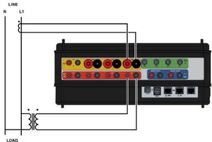
Figure 49: Single-phase voltage and current using CT/PT connections
5.1.1 Single-phase to neutral current and voltage example
From the main screen, press the voltage and current general settings option button , see section 4.3.10 for details. The user can configure the voltage and current channels, including the neutral, and select phase reference. For the first example, channels IA and VA will be selected for measurement and display, with VA selected for phase reference.
- In the voltage and current general settings screen the default will show all channels enabled. To view IA only, disable IB, IC and IN by pressing the enabled selector switch. Press the voltage channels button and disable VB, VC and VN. Press the green check button to return to the main screen.
- The user will then need to select the other two display panes by pressing the select panels to
display button , see section 4.3.9 for details. For this example, the current/frequency, voltage/frequency, power, and VA/PF panels are selected. After pressing the green check button, with the application of voltage and current the user should see something like the following screen.

line
| Variable | Value | | :--- | :--- | | A | 0.800 | | V | 112.02 | | φ | 0.00 | | Hz | 60.000 | | W | 77.405 | | Var | 45.237 | | Time (ms) | 89.654 | | Binary Inputs | 1 2 |Figure 50: Single-phase IA and VA with combined waveforms
Select the split waveform option, with the application of voltage and current the user could see something like the following example display.

other
| Current (A) | Voltage (V) | φ (°) | Hz | |---|---|---|---| | 0.800 | 111.97 | 0.00 | 60.000 | | 77.372 | 89.626 | | | | 45.237 | | | |Figure 51: Single-phase with split waveform option
From either of the above screens the user can use the snapshot button , see 4.3.6 for details, to
record either a picture of the screen, the data on the screen, or both. Pressing the freeze button will freeze the values on the display screen until pressed again. Note that the freeze icon changes colors when pressed. Pressing again will unfreeze the display and it will change back to its original color. It may also be used in conjunction with the snapshot button to freeze the values, and then take
a snapshot. Pressing the recorder button 📋, see 4.3.8 for details, allows the user to record the displayed data over a programable period of time.
5.1.2 1-phase, 2-wire, 1 12 element with CTs example

Figure 52: 1-phase, 2 wire, 1 12 element with CTs example test connections
From the main screen, press the voltage and current general settings options button , see section 4.3.10 for details. From this screen the user can configure the voltage and current channels and select phase reference. For this example, channel terminals IA, IB and VA will be selected for measurement and display, with VA selected for phase reference. The phase-to-phase voltages for this example will be potential inputs from Phases A and B, or V A-B, applied to voltage input terminal V1. To measure and display phase to phase voltage, go to the configuration screen by pressing the configuration button and select phase, see 3.4.3 for details.
- In the voltage and current general settings screen the default will show all channels enabled. To view IA and IB only, disable IC and IN by pressing the enabled selector switch. Press the voltage channels button and disable VB, VC and VN. Press the green check button to return to the main screen.
- The user will then need to select the other two display panes by pressing the select panels to
display button , see section 4.3.9 for details. For this example, the current, voltage, power, and VA/PF panels are selected. After pressing the green check button, with the application of voltage and current the user should see something like the following screen.

other
| Category | Value | |---|---| | A | 4.999 | | B | 5.004 | | C | 30.35 | | D | 150.37 | | E | 907.83 | | F | 531.04 | | G | 209.57 | | H | 0.00 | | I | 1,051.7 | | J | 0.86 | The image contains a table for the data being plotted in a table format. The values are explicitly labeled on each cell.Figure 53: 1-phase, 2 wire, 1 12 element example with combined waveforms
Select the split waveform option, with the application of voltage and current the user could see something like the following example display.
| I (A) | ψ (°) | W | Var | ||
| A | 4.998 | 30.36 | A | 907.88 | 531.51 |
| B | 5.004 | 150.38 | |||
| ψ (V±N) | ψ (°) | VA | PF | ||
| A | 209.86 | 0.00 | A | 1,052.0 | 0.86 |
Figure 54: 1-phase, 2 wire, 1 12 element example with split waveform option
From either of the above screens the user can use the snapshot button , see 4.3.6 for details, to record either a picture of the screen, the data on the screen, or both. Pressing the freeze button will freeze the values on the display screen until pressed again. Note that the freeze icon changes colors when pressed. Pressing again will unfreeze the display and it will change back to its original color. It may also be used in conjunction with the snapshot button to freeze the values, and then take a snapshot. Pressing the recorder button , see 4.3.8 for details, allows the user to record the displayed data over a programable period of time.
5.2 Three-phase Operation
The three-phase operation mode is intended for measuring all 3-phase quantities in a wye or delta installation.
APPLICATION NOTE:
Three phase watts are displayed in the three watt method.

NOTE:
Instrument defaults to VA as the phase reference. If current only is to be measured, the phase reference must be changed, see section 4.3.10.3 to change Phase Reference.
5.2.1 Selecting the configuration
The PMM-2 default configuration is set for three phase wye, with VA set as the phase reference, and the phase configuration is set for ABC counterclockwise (see section 3.4.3 phase angle configuration for details), Measure L-N; display L-N. The following is a typical three phase, 4-wire, connections, with CTs and direct connection of the voltage input terminals.
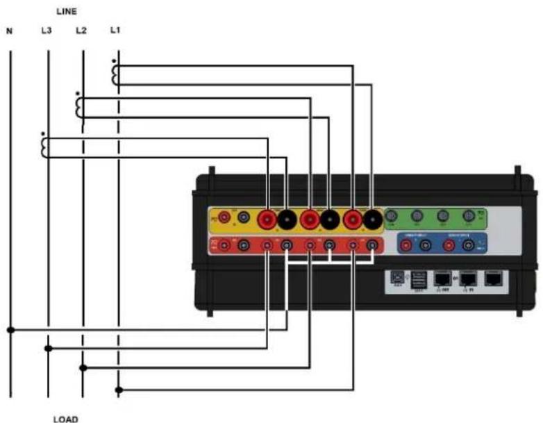
Figure 55: Three-phase, 4 wire, 3 element connections
5.2.2 Measuring functions
-
Anytime during the course of measurement, the snapshot or recorder can be activated.
-
The START or STOP inputs respond to a change of state. This change may be a dry contact opening or closure, or the initial application of an AC or DC voltage. The binary input terminals are isolated from the chassis ground and are independent of signal polarity.
- To save the measurements press the snapshot function button, or the Record function button. All saved data are time and date stamped.
- The instrument automatically defaults to true RMS measurement. To change the measurement mode to AVERAGE, press the voltage and current general settings options
button


APPLICATION NOTE: When measuring DC V, the instrument must be in the RMS measurement mode only and positive polarity connected to V1, V2, or V3 RED INPUT TERMINALS!
- The instrument defaults to automatic ranging. If manual ranging is desired, press the
voltage and current general settings options button and select the desired ranges. In the following example three-phase power measurement display, the neutral current (IN) and voltage (VN) were disabled in the general settings option screen.

other
| Category | Value | |---|---| | A | 4.999 | | B | 5.004 | | C | 5.005 | | Current (A) | -596.82 | | Time (ms) | 602.78 | | Value | VA PF | | A | 1,199.1 | | B | 1,201.3 | | C | 1,202.7 | | Voltage (V) | 0.87 | | Time (ms) | 0.87 |Figure 56: Example three-phase wye power measurements
- Please refer to section 5.2.3 if an external clamp-on current transformer is used.
5.2.3 Clamp-on current and potential transformer operation
For application requiring measurement of primary current using CT's, refer to sections 3.4.4 CT/PT ratios, and 4.3.10.2.8 current channel external CT settings.
There are two manners in which the clamp-ons can be utilized:
- Measuring primary current, watts and vars in a single- or three-phase installation.
- Verifying the ratios of CTs, used in relaying and metering installations.
The following sections detail the operation for each of these applications.
5.2.3.1 Measuring primary current with clamp-on CT
- For this application, connect the clamp-on CT(s) directly to the appropriate current channel terminals (CT1, CT2, CT3, or CT4 for clamp-on CT's with low-voltage BNC connector outputs) on the top panel. Up to four clamp-ons can be used for three-phase with neutral applications. Note that the CTs are only rated for 600 V class circuits.
- All measuring functions are explained in sections 4.3.9 and 4.3.10.
5.2.3.2 Verifying the ratios of CTs
Verification of CT ratios requires an appropriate variable high current source and the PMM-2. To verify CT ratios, use I1 and I2, with I1 measuring the primary current using a clamp-on CT, and I2 to measure the secondary current.

DANGER: DO NOT DISCONNECT THE CT SECONDARY IF IN A LIVE CIRCUIT. EXTREMELY HIGH VOLTAGES CAN OCCUR CAUSING SERIOUS INJURY OR DEATH!
- Connect the clamp-on CT directly to the primary of the CT under test, and connect the voltage output of the clamp-on to CT1 current channel input terminal on the top panel. Connect the secondary of the CT under test to the I2 current channel input terminals on the top panel.
- From the main screen, press the general settings button. Use I1 for the clamp-on CT, by enabling the external CT and set the scale for the appropriate mV/A. If in a noisy environment, switch on the low pass filters for I1 and I2 to block the high frequency noise from effecting the measurements.
- Disable I3 and IN, leaving I1 and I2 enabled. Press the phase reference button and select I2. The following example screen should appear on the display.

Figure 57: Current general settings screen
- Press on voltage channels and disable all voltage channels. Press the green check button to return to the main screen.
- In the main screen display, press on the select panels to display button. Enable the current panel only and deselect all other options. Then only the two current channels will be displayed, see the following example. Press the green check button to return to the main screen.

flowchart
graph TD
    A["Select Panels To Display"] --> B["Current/Frequency"]
    A --> C["Voltage/Frequency"]
    A --> D["Frequency"]
    A --> E["Current"]
    E --> F["Voltage"]
    E --> G["Power"]
    A --> H["Current Min/Max"]
    A --> I["Voltage Min/Max"]
    A --> J["KVA/PF"]
    A --> K["Timer"]
    L["Select Chart Mode"] --> M["Combined Waveform"]
    L --> N["Polar"]
    L --> O["Split Waveform"]
    L --> P["Combined Waveform With Binary"]
    L --> Q["Polar With Binary"]
    L --> R["Harmonics"]
Figure 58: Example panels to display for CT testing
- Apply current to the CT under test and measure the results to calculate the CT ratio, see the following example.

Figure 59: Checking CT ratio with clamp-on CT
Note the measured primary current measured with the clamp-on CT shown A phase and the Secondary current is shown for B phase. In the above example the primary current is 997.43 A, with the measured secondary current 5.013 A. The calculated ratio is 200.1 to 1, or basically 200:1.
5.3 Timing tests
Timing tests can be started using Binary Input #1 (see section 4.3.5) or using the current start feature (see section 4.3.4.1.2) selecting analog non-zero channel IA. The timer can be stopped using binary input #2. If performing a dropout timing test the timer can be started when current is removed (see section 4.3.4.1.2) selecting analog zero channel IA. Two examples are provided in the following sections.
5.3.1 Timing test using binary inputs
The timer can be started with the closing of dry contacts, or opening of dry contacts, or application of an AC or DC voltage, or removal of an AC or DC voltage (see section 4.3.5 for details).

-
Press the timer configuration button and enable T1 and disable any other Timing tests such as T2. Configure T1 start condition to binary input high. To start the timer from dry contacts, connect the start contacts to binary input #1 terminals, and press on the binary input
configuration button (see section 4.3.5). -
For normally open dry contacts, leave BI #1 type at 📄, and set the trigger to signaling a closing of the contacts.
APPLICATION NOTE: If using an AC/DC voltage applied to start or stop the timer, press the type button to change from normally open dry contacts to AC/DC voltage applied. The voltage threshold defaults to 10 V. If using a TTL signal to start or stop the timer press the AC/DC voltage button and the type window will change to
-
Connect the stop contacts to binary input #2 terminals. For normally open dry contacts, leave BI #2 type at ☐, and set the trigger to ⏚ signaling a closing of the contacts. For AC/DC voltage applied stop, see the APPLICATION NOTE above.
-
Press the green check button to return to the main screen.
-
In the Main screen press the timer reset button [icon]. When the start contacts close the timer will start and when the stop contacts close it will stop the timer and freeze the values
displayed on the screen. To un-freeze the values press the freeze button
5.3.2 Timing test using current start
This example illustrates a timing test on a single-phase overcurrent relay using an external current source like a state's company resistive load box or a transformer load like the SVERKER 650.
- Series the current output terminals of the external current source through the current input terminals I1 on the PMM-2. Press the voltage and current general settings options button

(see section 4.3.10.2.) deselect I2, I3, and IN. Since no voltages are used for this test, deselect all the voltage channels.

-
Press the timer configuration button and enable T1 and disable any other timing tests such as T2.
-
Configure T1 start condition to analog non-zero and set the channel to IA. Note that when current is applied to IA it will start the timer. The units measured defaults to s for seconds. Press on the button to change to either ms (milliseconds) or cy for cycles.
-
Connect the relay trip contact to binary input #2 terminal and press on the binary input configuration button (see section 4.3.5). Leave BI #1 trigger at . For normally open dry contacts, leave BI #2 at , and set the trigger to signaling a closing of the contacts.
-
Press the timer reset button 📄. Begin the test by applying current to the relay, and the timer will start. When the relay trips it will stop the timer and freeze the values of the current, timer and waveform at the point of the trip.

APPLICATION NOTE: The user will need to turn off the test current after the relay of high values of current are being used, any significant delay could overheat the and cause damage.
5.4 Timed data recording
To make a timed recording of data over a period of time, press the recorder button. The following window will appear.

Figure 60: Example recorder capture options screen
The interval is programmable in seconds, and the duration is programmable in hours, or tenths of hours (as shown in the above example figure). In the above example, a single phase recording is being programmed to capture data every 60 seconds (1 minute) for a period of 0.5 hours (30 Minutes).

APPLICATION NOTE: The size of the recording may be limited due to the sampling see section 3.4.2.6.2 waveform capture rate for details.
The recordings are in a .csv data format, and time stamped, so that the user can later view, or download the recordings into an Excel file, for detailed evaluation. The following example details the programming of this function:
- Configure the main screen measurement panels for the desired recorded values
- Press the recorder button.
- Enter a file name for the recorded data by pressing the file name line.
-
Enter the desired recording time interval in seconds. Example: for a recording, every 5 minutes enter 60 x 5 or 300 seconds.
-
Enter the duration of the recording time in hours, or 10 ^th of an hour. In the above example 0.5 Hours was entered.
- Press the start button to begin the recording. To stop the recording press the recorder button again and press the stop button. Note that the recording can be stopped at any point, the user does not have to wait until the end of the set duration time.
- Once the recording is completed the user can view the recorded data by pressing on the
file folder. When the folder opens the user will see the following figure.
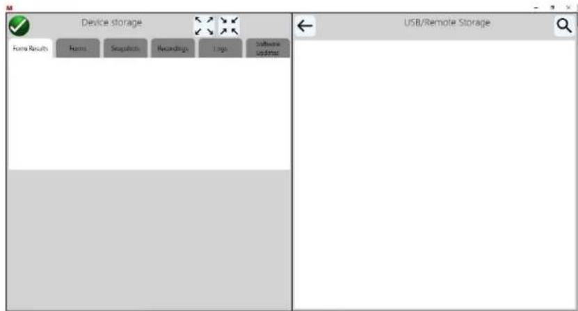
Figure 61: File folder main screen
- Press on the Recordings tab. The user will see all of the recording listed. For the example, Single Phase Recording Example.csv, pressing on the file will open the file, see the following example.

Figure 62: Example recording data file
Each row is a single recording showing each current, voltage, phase angle, frequency, power, VA, and Power Factor, with the date time stamp. From here the user can export the file to the USB port for downloading onto a USB memory stick or remote data storage. From there the .csv file can be easily imported into an Excel spreadsheet.
5.5 PMM-2 software file management
The user uses the file management screen to access files stored in the PMM-2 internal memory.
To access the file management system, touch the file folder in the top tool bar of the meter screen. This display will allow test files to be opened, viewed, moved to a USB stick for remote storage, or deleted by the user. Pressing on the file folder presents the user with the following display screen.

Figure 63: File management main screen
5.5.1 File management main screen
There are six file folders, which are associated with different file recording features within the PMM-2 software.
5.5.1.1 Forms and form results folder
Form results are test reports that have been saved, see section 4.3.3 reports. Pressing on the reports button takes the user to the report's options – select new form or data view. Once data is saved, pressing the forms folder list the user report forms.
5.5.1.2 Snapshots folder
When conducting a test pressing the snapshot button will capture the display screen, see section 4.3.6 for more details. Giving the snapshot a file name will save it to the snapshot file folder. The user can select to save it as a screen shot picture, or data only, or both. Pressing the snapshot file folder will present the user with a listing of all the saved snapshots, see the following example.

Figure 64: Example three-phase snapshot screen shot
In the above figure the screen shot (.png file) was selected, with a preview of the capture screen. If the data file (.csv file) had been selected the screen data would have appeared. Pressing on the expansion button will expand the preview screen. Pressing the reduce button will return the user to the previous screen. Pressing the delete will delete the file from the folder. Pressing the move button will move the selected file to the USB port for file transfer. Files can be shared or transferred to the PMM-2 by using a USB memory stick, placing it into the USB A port on top of the PMM-2, go to the file folder, select the file that will appear in the right-hand side of the screen and use the import file button to import into the snapshot folder.
5.5.1.3 Recordings folder
Recordings can be made and saved to the internal memory, see section 4.3.8 recorder button, and section 5.4 for a timed recording example.
5.5.1.4 Logs folder
Log files can be made of the PMM-2 software and saved to internal memory, see section 3.4.2.7 for details. Two types of log files can be created, AppLog (application software log), and DriverLog (driver commands sent). These are text files and can be viewed from the logs folder window.
Pressing the move button → will move the selected file to the USB port for file transfer. Files can be shared or transferred to the PMM-2 by using a USB memory stick, placing it into the USB A port on top of the PMM-2.
5.5.1.5 Software updates
Software and firmware updates and can be upgraded using a USB thumb drive or using the ethernet port via windows explorer.
6.0 Maintenance
NOTE : There are no user replaceable parts within this product, other than the battery.
6.1 General maintenance
Ensure the unit is kept clean and dry after use. Place the unit in the transit case when not in use. Test leads and adaptors should be checked before use for damage and continuity.
The unit utilizes surface mount technology (SMT) and other components which require little or no service except for routine cleaning. The unit should be serviced in a clean atmosphere away from energized electrical circuits.
6.2 Cleaning
To clean the unit, disconnect the power cord from the unit. Switch off the unit. Never use spray liquids or industrial cleaners. Some cleaning solvents can damage electrical components and should never be used. Remove dust with dry, low pressure, compressed air. Use a lightly damp cloth (not dripping wet) to wipe off the unit.
6.3 Battery
The PMM-2 has a rechargeable Lithium-ION battery with internal automatic charger. Safety features include internal battery overcharging and charge exhaustion protection. Battery energy is limited to 97.2 Watt-hour (to carry on-board a commercial airliner the battery energy must not exceed 100 Watt-hour). The battery recharges when plugged into an appropriate source and turned on. The battery is RoHS compliant.
6.3.1 Battery status
Battery condition icon is positioned at the top right-hand corner of display. This icon is displayed at all times when the instrument is switched on. When running the icon will indicate state of charge, the icon will be filled in proportion to the state of charge
6.4 Updating PMM-2 software and firmware
Download firmware upgrade via Megger Website
Updating Firmware via Megger Website
To download the latest PMM-2 software and firmware from the Megger website,
- Go to WWW.Megger.com
- Log In. If you have not registered before you will need to do so first.
- Go to Products / Relay and protection testing / Protection system tools and click on the picture of the PMM-2 unit.
-
Click on the software tab
-
Click on the PMM-2 software or firmware #.### ↓Download button
-
You will see a pdf document with detailed instructions on how to update the software and firmware on the PMM-2 unit. Download the PMM-2_Firmware_#.### or PMM-2_software_#.### and install per the instructions.
USB memory stick: With the PMM-2 powered up, insert the USB memory stick into the USB type A port on top of the PMM-2. Press the configuration screen button, with the System tab highlighted press the system info button, then press Update System button. At that point, a window will pop up with the current software version on the PMM-2, and the version of the software on the USB thumb drive. Select the continue button and the software will automatically be upgraded to the unit. If a new firmware was found the user will be prompted regarding the upgrade and upon acknowledgement of the new firmware the upgrade process will start. On completion of the upgrade the user will be prompted to power cycle the PMM-2 unit once the beeping sound is heard.
7.0 Battery replacement
The battery in the PMM-2 is a Rechargeable Lithium-ION battery and is not field replaceable, see section 10 for repair and return authorization contact information.
8.0 Specifications ^1
Input Power
90 to 253 V AC, 1∅, 50/60 Hz, 150 VA.
Battery
Rechargeable battery with internal automatic charger. Safety features include internal battery overcharging and charge exhaustion protection. Battery energy is limited to 97.2 Watt-hour (to carry on-board a commercial airliner the battery energy must not exceed 100 Watt-hour). The battery is RoHS compliant.
Operation time
± 4 hours continuous on full charge – actual operation time limited to 97.2 Watt-hour battery.
Voltage
0 - 1000 V (AC/DC)
4 Independent isolated inputs
Isolation voltage: 1200 V
Resolution: 0.000 V – 99.999 V 100.00 V – 999.99 V 1000.0 V
Accuracy ^2 :
AC/DC voltage
Ranges Accuracy
0 - 299.999 V: ± 0.05 % of reading ± 40 mV
300 - 1000.00 V: ± 0.05 % of reading ± 65 mV
Input impedance: 0 - 34.999 V, 100 kΩ 35 V - 1 kV, 5 MΩ
Measured: RMS or AVG
Crest factor: 3 or maximum 1450 V peak
Current
4 Total isolated inputs
3 Independent isolated inputs: 0 - 100 A (AC/DC)
Isolation voltage: 300 V
1 Independent isolated input: 0 - 32 A (AC/DC)
Isolation voltage: 300 V
Resolution: 0.000 mA - 99.999 mA
0.100 A - 9.999 A
10.000 A - 99.999 A and 100.00 A (Channel 1 - 3)
10.000 A - 32.000 A (Channel 4)
Minimum current measurement: 2 mA
Burden at 5A: ≤ 0.1 VA
Crest factor: 3 or maximum 145 A peak, channels 1-3, or maximum 46 A peak, channel 4
Accuracy ^2 channels 1 – 4:
AC/DC amperes:
Ranges Accuracy
| 0 – 0.999999 A | ± 0.05 % of reading ± 2 mA, |
| 1 – 9.99999 A | ± 0.05 % of reading ± 10 mA, |
| 10 – 32.0000 A | ± 0.1 % of reading ± 10 mA, Channel 4 |
| 32 – 100 A | ± 1 % of reading, Channel 1-3 |
CT inputs (low-level inputs):
Each current channel can be selected for low level input from clamp on CT's. CT secondary current and/or CT primary current scaling can be entered and automatically calculated for display.
4 Total isolated inputs
0 - 1 V (AC/DC)
Isolation voltage: 50 V AC
Resolution: 0.000 V - 1.000 V
Accuracy ^2 : ± 0.05 % of reading ± 25 mV ± CT accuracy
Low-level measurement
Voltage range
+/-10VDC
Accuracy ^2 : ± 0.003 % of reading ± 0.02 % of range
Current ranges
+/-1 mA DC
+/- 20 mA DC
Accuracy ^2 : ± 0.003 % of reading ± 0.02 % of range
Phase angle
Resolution: 0 - 360.00° lead or lag or ± 0 - 180.00°, 0.01°
Accuracy ^2 : ±0.08^ input levels above 30 V and 1.0 A (using current as reference), ±0.5^ input levels below 30 V and above 3 V and 0.02 A, ±2^ input levels down to 0.002 A.
Power
Resolution: ± 0 - 100 KW, 0.1 %
Accuracy ^2 : ± 0.2 % of VA.
Reactive power
Resolution: ± 0 - 100 KVAR, 0.1 %
Accuracy ^2 : ± 0.2 % of VA.
Power factor
± 1.00 PF
Accuracy ^2 : 0.01 PF
Frequency
Resolution: 10 - 1000 Hz, 0.0001 Hz
Accuracy ^3 : ± 4 ppm (0.0004%) of reading
Harmonics
Measures all harmonic content simultaneously of any selected voltage or current, up to the 50th harmonic.
Accuracy ^2 : ± 5 % of reading
Time:
Resolution:
Seconds:
0.0000 to 9.9999 - 5 digits
Greater than 10.0000 - 6 digits
Cycles:
5 digits or maximum 0.1 cycle
Seconds mode
200 s or ± 0.005 % of reading, whichever is greater when initiated by a dry contact, a DC potential above 5 V or an AC potential above 115 V AC*.
Cycles mode
± 0.5 cycle when initiated by a dry contact, a DC potential above 5 V or an AC potential above 115 V AC*.
* AC voltage accuracy is worse at lower voltages and is ± 8 ms in worst case (5 V RMS applied just following wave-shape peak).
Start/stop inputs
5 - 300 V (AC or DC) start or stop inputs. AC or DC applied/removed, or dry contact closure or opening.
Voltage applied
Timer starts or stops when an AC or DC potential (5 to 300 V) is applied.
Voltage removed
Timer starts or stops when an AC or DC potential (5 to 300 V) is removed.
Input resistance
1000 Ω min.
Data input/output
Ethernet: There are two Ethernet ports. IN Port – Primary PC connection Port for downloading data.
OUT port – Future use.
USB A ports: Two type A ports available. These ports are used to update the firmware and software in the system.
USB B port – The USB B port interface requires a Type B “downstream” connector and is a communication and control port when used with a PC and Megger software.
Bluetooth (optional): An optional wireless Bluetooth interface is available (future).
Display screen
The display provides high resolution and features wide viewing angle technology and a large screen with high luminance.
Dimensions: 8.5 H X 5.3 W inches (215.9 H X 134.6 W mm), 10.1 inches Diagonal (256.5 mm)
Display: 262k colors, backlit, 800:1 contrast ratio, projected capacitive multi touch screen, 700 nits panel brightness, 1280 x 800 resolution
Languages: English, French, Spanish and German
Dimensions
13.5 W x 9 H x 6 D in. - 342.9 W x 228.6 H 152.4 D mm
Weight
13.4lbs (6.0 kg)
Operating temperature
-15° to 55° C (5° to 131° F)
Storage temperature
-30° to 75° C (-22° to 167° F)
Ingress protection
IP 20
Conformance Standards
Safety: EN 61010-1, overvoltage category 600V Cat IV, 1000 V Cat III
Shock: EN/IEC 60068-2-27
Vibration: EN/IEC 68-2-6
Transit drop: ISTA 1A
Free fall: EN/IEC 60068-2-32
Drop/topple: EN/IEC 60068-2-31
Electromagnetic compatibility
Emissions: EN 61326-2-1, EN 61000-3-2/3, FCC subpart B of Part 15 Class A
Immunity: EN 61000-4-2/3/4/5/6/8/11
9.0 Accessories
9.1 Included accessories
| Included Standard Accessories | Part Number |
| Power Cord - Depending on the style number, the unit will come with one of the following, | |
| Line cord, North American | 6828 |
| Line cord, Continental Europe with CEE 7/7 Schuko Plug | 90015-268 |
| Line cord, International color-coded wire | 90015-269 |
| Line cord, United Kingdom | 90015-270 |
| Ethernet cable for interconnection to PC, 210cm (7 ft.) long (Qty. 1 ea.) | 90003-684 |
| Instruction manual USB memory stick | 87865 |

9.2 Table of optional accessories
The test leads and test lead accessories are optional. Test leads and accessories can be ordered with the unit, or later.
| Descriptions of optional test leads and accessories | Part Number | |||||
 | Color-coded, sleeved test leads: Sleeved test leads, one red, one black, 200 cm (78.7") long, 600 V, 32 A CAT II RoHS compliant. | 2008-539-2 | ||||
 | Color-coded, sleeved combination voltage test leads:Sleeved, color coded 6 x 4 test lead, 200 cm (78.7") long, 600 V,32 A CAT II* RoHS compliant. | 2008-540-2 | ||||
 | Color-coded, sleeved combination current test leads:Sleeved, color coded 6 x 6, 200 cm (78.7") long, 600 V, 32 ACAT II* RoHS compliant. | 2008-541-2 | ||||
 | Cable/spade lug adapter (small): Small lug to fit most small terminal blocks.Lug adapter, red, 4.1 mm, rated up to 1000 V/20 A CAT II | 684004 | ||||
 | Cable/spade lug adapter (small): Small lug to fit most small terminal blocks.Lug adapter, black, 4.1 mm, rated up to 1000 V/20 A CAT II | 684005 | ||||
 | Extra-long test lead:Black, use with voltage/current inputs, or binary I/O, 360 cm long (12 ft) 600 V/ 32 A CAT II.Red, use with voltage/current inputs, or binary I/O, 360 cm long (12 ft) 600 V/ 32 A CAT II. | 2003-1722003-173 | ||||
 | Alligator/crocodile clip: Excellent for test connections to terminal screws and pins where spade lugs cannot be used.Red, use with test leads up to 1000 V CAT III /32 A.Black, use with test leads up to 1000 V CAT III /32 A. | 684006684007 | ||||
 (Black Clip Shown) (Black Clip Shown) | Fused test clip:Black with 20 mm steel jaws, 1000 V AC/DC, CAT III, (fuse not included).Red with 20 mm steel jaws, 1000 V AC/DC, CAT III, (fuse not included).Blue with 20 mm steel jaws, 1000 V AC/DC, CAT III, (fuse not included).Yellow with 20 mm steel jaws, 1000 V AC/DC, CAT III, (fuse not included). | 90022-98290022-98390022-98490022-985 | ||||
 | Digital multimeter Fuse, 1 each, Fast Acting, 11 A, 1000 V AC/DC. Note that each test clip will require 1 each of the fuse.Cable/spade lug adapter (large): Large spade lug fits older terminal blocks, or STATES® Company FTP10 or FTP14 Test paddles, ABB, or General Electric test plugs with screw down terminals.Lug adapter, red, 6.2 mm, use with test leads up to 1000 V/20 A CAT II.Lug adapter, black, 6.2 mm, use with test leads up to 1000 V/20 A CAT II. | 90026-411 | ||||
| 684002684003 | ||||||
 | Flexible test lead adapter: Use with rail-mounted terminals or screw clamp connections where spade lugs and crocodile/alligator clips cannot be used.Flexible test lead adapter, black, 1.8 mm male pin, use with test leads up to 1000 V CAT III /32 A. | 90001-845 | ||||
 | Current leads with States I-Probe:The measurement of secondary current from a distribution test switch can be obtained by using the 20 A StatesTM current plug.Set of 3 states current plugs, 3 ft. 6 in. (1m) | 1014-727 | ||||
 | Jumper lead: Used to common neutral returns togetherJumper lead, black, 12.5 cm (5") long, use with voltage and current neutral returns, 600 V, 32 A, CAT II. | 2001-573 | ||||
 | Clamp-on ac current probe:The clamp-on current probe makes it easy to check current path in a wired distribution panel without worry of interrupting a current circuit in service.Nominal range: 5 A, 100 AMeasurement range: 5 A: 0.005 to 6 A100 A: 0.1 to 120 ATransformation ratio: Voltage outputOutput Signal: 5 A: 200 mV/A100 A: 10 mV/AAccuracy:5 A range: | 1014-723 | ||||
| Ip | 0.005A | 0.05A | 0.5A | 5 A | ||
| Vs% | 1.5%+0.02mV | 1.5% | 1 % | 1 % | ||
| 100 A range: | ||||||
| Ip | 0.1A | 1 A | 10A | 100A | ||
| Vs% | 1 %+0.02mV | 1 % | 1 % | 1 % | ||
| Dimensions: 5.47 H x 2.00 W x 1.18 D in.139 H x 51 W x 30 D mmWeight: 6.5 oz (180g) | ||||||
 | Clamp-on ac/dc current probe:The ac/dc current probe is designed for ac/dc current measurement capabilities using “Hall Effect” technology.The unique design is made for probing in crowded wiring environments.Nominal range: 10 A and 100 AMeasurement range: 100 mA to 100 ATransformation ratio: Voltage outputOutput signal: 10 A: 100 mV/A100 A: 10 mV/AAccuracy:50 mA to 10 A peak: 3 % of reading ± 50 mA500 mA to 40 A peak: ± 4 % of Reading ± 50 mA40 A to 100 A peak: ± 15% max at 100 AOutput termination: 6.5 ft (198 cm) coaxial cableDimensions: 9.09 H x 1.42 W x 2.64 D in. (231 H x 36 W x 67 D mm)Weight: 11.6 oz (330 g) with battery | 1014-721 | ||||

AC current probe:
The measurement of primary current can be measured by using the optional clamp-on current probe. The high accuracy voltage output current probe is made for tight spaces such as crowded wiring.
1014-722
Current range: 1 mA to 10 A AC, continuous
Output signal: 100 mV AC/A, 1 V at 10 A
Accuracy class: 1 mA to 10 A: 2 % ± 2 mA
Maximum cable diameter: 0.47 in. max (12 mm)
Dimensions: 1.26 x 4.5 x 0.87 in. (32 x 115 x 22 mm)
Weight: 6 oz (160 g)
10.0 Calibration, repair, and warranty
Megger operates fully traceable calibration and repair facilities to make sure your instrument continues to provide the high standard of performance and workmanship that is expected. These facilities are complemented by a worldwide network of approved repair and calibration companies, which offer excellent in-service care for your Megger products.
Since the PMM-2 uses surface mount technology, repairs are beyond the basic capabilities of the majority of customers and should be referred to the service department at Megger or handled through the Megger representative.
For calibration and service requirements for Megger PMM-2 instruments contact:
Megger
4545 W Davis street
Dallas, Texas 75211-3422 USA.
PHONE: 1-214-330-3519
FAX: 1-214-331-7399
! If the unit is still within the original warranty period, or limited warranty period following factory servicing, the factory must be contacted before attempting any repairs or the warranty will be void.
10.1 Warranty
Megger warrants the equipment sold by Megger, or our authorized agents, to be free from defects in material and workmanship, reasonable wear and tear excluded, for a period of 12 months from date of shipment. Since Megger has no control over conditions of use, no warranty is made or implied as to suitability for customer's intended use beyond the units normal performance specifications. No other warranty is either expressed or implied. Megger shall not be liable for consequential damages.
Warranty service will be performed on the equipment at the Megger factory. The customer shall prepay shipping charges for units returned to Megger. Megger shall pay for the return of the repaired or replaced unit to the customer (repair or replace at Megger's option), provided that the Instrument has not been altered, modified or repaired by unauthorized personnel, and that our examination discloses to our satisfaction that any improper operation or failure was not the result of improper use, negligence or accident, exceeding environmental limits, or connecting the Instrument to incompatible
equipment. The customer is asked to obtain a return authorization number from Megger PRIOR TO returning a unit for service, see return procedure.
10.2 Return Procedure
- When an instrument requires recalibration, calibration certification, or in the event of a repair being necessary, a return authorization (RA) number must first be obtained from the address shown above. The following information is to be provided to enable the service department to prepare in advance for receipt of your instrument and to provide the best possible service to you:
• Model number, PMM-2.
- Serial number (found on the display under configuration, system tab, view system info tab, or on the unit enclosure, or on the calibration certificate).
- Reason for return (for example, calibration required, or repair).
- Details of the problem if the instrument is to be repaired.
- Provide a return address, your name, and how to contact you should the factory need to discuss the service request.
- Make a note of the RA number. A return label can be emailed or faxed to you if required.
Save the original shipping container for future use. The shipping container is designed to withstand the rigors of shipping via a common commercial carrier. For example, you may wish to reship your unit to Megger for an annual calibration recertification.
- Pack the equipment appropriately to prevent damage during shipment. If a reusable container is utilized, the unit will be returned in the same shipping container if it is in suitable condition.
NOTE: Ship the equipment without nonessential items such as test leads. These items are not needed by the factory to perform service.
-
Before the instrument is sent to Megger, freight prepaid, make sure that the return label is attached or that the RA number is clearly marked on the outside of the package, and on any correspondence. Copies of the original purchase invoice and packing note should be sent simultaneously by airmail to expedite clearance through customs. In the case of instruments which require repair outside the warranty period, an immediate quotation can be provided when obtaining the RA number.
-
Track the progress online at www.megger.com
11.0 Decommissioning
11.1 WEEE Directive

The crossed out wheeled waste bin placed on Megger products is a reminder not to dispose of the product at the end of its life with general waste. Please utilize your local WEEE collection facilities or observe all applicable local requirements.
Megger is registered in the UK as a Producer of Electrical and Electronic Equipment. The Registration No is WEE/HE0146QT.
For further information about disposal of the product consult your local Megger company representative or distributor or visit your local Megger website.
11.2 PMM-2 and battery disposal
The crossed out wheeled bin symbol placed on the unit as a reminder not to dispose of the PMM-2 with general waste when they reach the end of their usable life. The battery within the unit must be properly disposed.
For disposal in the UK contact Megger Ltd Dover. For disposal of batteries in the EU contact your local distributor. For disposal in the USA check your local recycling centers. Megger is registered in the UK as a producer of batteries (registration No.: BPRN00142). For further information see www.megger.co
- Revision history
- Declaration of conformity
- Table of contents
- APPLICATIONS 44
- MAINTENANCE....57
- BATTERY REPLACEMENT....58
- SPECIFICATIONS 59
- ACCESSORIES....62
- CALIBRATION, REPAIR, AND WARRANTY 66
- DECOMMISSIONING 67
- Table of figures
- Introduction
- Product description
- Features
- Applications
- Megger website
- Safety Warnings and Standards
- Warnings, Cautions and Notes
- Instrument overview
- PMM-2 onboard display screen and power Input
- Input line cord
- NOTE: Figure 1 is the preferred orientation for using the PMM-2
- Input power cord
- Top panel communication ports and input terminals
- Maximum input voltage rating of CT1 to CT4 is 1 V.
- Configuration of PMM-2 software
- Configuration
- Screen exit
- System configuration options
- Virtual alphanumeric keyboard
- Configuration profile options
- Label settings
- Voltage character
- Global settings
- Language
- Set system date and time
- System info (information screen)
- Screen dimming
- Sample settings
- Fundamental frequency
- Waveform capture rate
- Pre-trigger samples
- Diagnostic logging settings
- Phase angle configuration screen
- CT/PT ratios
- Colors options
- General operating instructions
- Safety considerations
- Set up of PMM-2
- Unpack system
- Initial startup
- Battery
- Battery charging
- Main startup screen
- ① Connection button
- ② The configuration button
- ③ Report options button
- ④ Timer configuration button
- Timer configuration
- Start/stop condition
- Channel selection
- Mode selection
- ⑤ Binary input configuration button
- Trigger configuration button
- ⑥ Snapshot button
- ⑦ Record button
- ⑧ Select panels and charts to display button
- Enable current/frequency panel
- Enable current panel
- Enable voltage/frequency panel
- Enable voltage panel
- Enable frequency panel
- Enable power panel
- Enable VA/PF panel
- Enable timer panel
- Charts off
- Combined waveform mode
- Combined waveform with binary mode
- Polar mode
- Polar mode with binary
- Split waveform mode
- Harmonics mode
- ⑨ Voltage and current general settings options
- Voltage general settings options
- Voltage channel enable/disable switch
- Voltage channel mode options
- Voltage channel integration cycles
- Voltage channel integration seconds
- Voltage channel range options
- Voltage channel trigger setting options
- Voltage channel low pass filter
- Voltage channel external CT settings
- Current general settings options
- Current channel enable/disable switch
- Current channel mode options
- Current channel integration cycles
- Current channel DC integration seconds
- Current channel range options
- Current channel trigger setting options
- Current channel low pass filter
- Current channel external CT settings
- Maximum input voltage rating of CT1 to CT4 is 1 V
- Phase reference
- ⑩ Freeze button
- ⑪ Help ? button
- ⑫ File folder button
- ⑬ Battery icon
- ⑭ Graphic display screen
- Graphic display zoom button
- Binary Inputs #1 and #2 status
- Applications
- Single-phase operation
- Single-phase to neutral current and voltage example
- 1-phase, 2-wire, 1 12 element with CTs example
- Three-phase Operation
- APPLICATION NOTE:
- NOTE:
- Selecting the configuration
- Measuring functions
- Clamp-on current and potential transformer operation
- Measuring primary current with clamp-on CT
- Verifying the ratios of CTs
- DANGER: DO NOT DISCONNECT THE CT SECONDARY IF IN A LIVE CIRCUIT. EXTREMELY HIGH VOLTAGES CAN OCCUR CAUSING SERIOUS INJURY OR DEATH!
- Timing tests
- Timing test using binary inputs
- Timing test using current start
- Timed data recording
- PMM-2 software file management
- File management main screen
- Forms and form results folder
- Snapshots folder
- Recordings folder
- Logs folder
- Software updates
- Maintenance
- General maintenance
- Cleaning
- Battery
- Battery status
- Updating PMM-2 software and firmware
- Download firmware upgrade via Megger Website
- Updating Firmware via Megger Website
- Battery replacement
- Specifications 1
- Input Power
- Battery
- Operation time
- Voltage
- Independent isolated inputs
- Accuracy 2 :
- AC/DC voltage
- Current
- Total isolated inputs
- Independent isolated inputs: 0 - 100 A (AC/DC)
- Independent isolated input: 0 - 32 A (AC/DC)
- Accuracy 2 channels 1 – 4:
- AC/DC amperes:
- Ranges Accuracy
- CT inputs (low-level inputs):
- Low-level measurement
- Voltage range
- Current ranges
- Phase angle
- Power
- Reactive power
- Power factor
- Frequency
- Harmonics
- Time:
- Resolution:
- Seconds mode
- Cycles mode
- Start/stop inputs
- Voltage applied
- Voltage removed
- Input resistance
- Data input/output
- Display screen
- Dimensions
- Weight
- Operating temperature
- Storage temperature
- Ingress protection
- Conformance Standards
- Electromagnetic compatibility
- Accessories
- Included accessories
- Table of optional accessories
- AC current probe:
- Calibration, repair, and warranty
- Warranty
- Return Procedure
- Decommissioning
- WEEE Directive
- PMM-2 and battery disposal
Brand : Megger
Model : PMM-2
Category : Measurement