
P.I.P.-AF - Audio processor CROWN - Free user manual and instructions
Find the device manual for free P.I.P.-AF CROWN in PDF.


| Brand | Crown |
| Model | P.I.P.-AF |
| Product Type | Audio Amplifier |
| Dimensions (W x H x D) | 19.0 x 3.5 x 12.0 inches (rack mount) |
| Weight | 15.0 lbs (6.8 kg) |
| Power Supply | 120V AC, 60Hz |
| Power Output (RMS) | 500W per channel into 4 ohms |
| Frequency Response | 20 Hz – 20 kHz (±0.5 dB) |
| Total Harmonic Distortion (THD) | <0.1% |
| Input Sensitivity | 1.23V (4 ohm load) |
| Input Impedance | 10 kΩ (balanced) |
| Output Impedance | 4 – 8 Ω |
| Cooling Method | Variable speed fan, front-to-rear airflow |
| Protection Features | Short circuit, thermal overload, DC offset, under/over voltage |
| Controls | Volume knobs, gain switches (26dB/1.4V), input selector |
| Indicators | Power (blue), Signal (green), Clip (red), Protect (amber) |
| Input Connectors | XLR, 1/4" TRS, RCA (per channel) |
| Output Connectors | Binding post (5-way) and Speakon® |
| Rack Mountable | Yes, standard 19 inch with included rack ears |
| Certifications | CE, UL, FCC Class B |
| Operating Temperature | 0°C to 40°C |
| Storage Temperature | −20°C to 60°C |
| Spare Parts & Repairability | Replaceable fan, fuses, and power supply module; serviceable by qualified technicians |
| Maintenance | Regular cleaning with dry cloth; check air filters monthly |
| General Information | Designed for professional live sound and installed sound applications |
Frequently Asked Questions - P.I.P.-AF CROWN
User questions about P.I.P.-AF CROWN
0 question about this device. Answer the ones you know or ask your own.
Ask a new question about this device
Download the instructions for your Audio processor in PDF format for free! Find your manual P.I.P.-AF - CROWN and take your electronic device back in hand. On this page are published all the documents necessary for the use of your device. P.I.P.-AF by CROWN.
USER MANUAL P.I.P.-AF CROWN
natural_image
Simple line drawing of a crown inside a rounded square frame (no text or symbols)P.I.P.-AF
PROGRAMMABLE INPUT PROCESSOR
OWNER'S MANUAL
Distributed in North America as Crown. ® Exported as Amcron. ®
©1993 by CROWN INTERNATIONAL, INC.
Mailing Address:
P.O. Box 1000
Elkhart, IN 46515
Service Department:
57620 C.R. 105
Elkhart, IN 46517
Amcron, ® Crown, ® Com-Tech, ® Macro-Tech ® and P.I.P. ® are registered trademarks of Crown International, Inc.
K80539-8
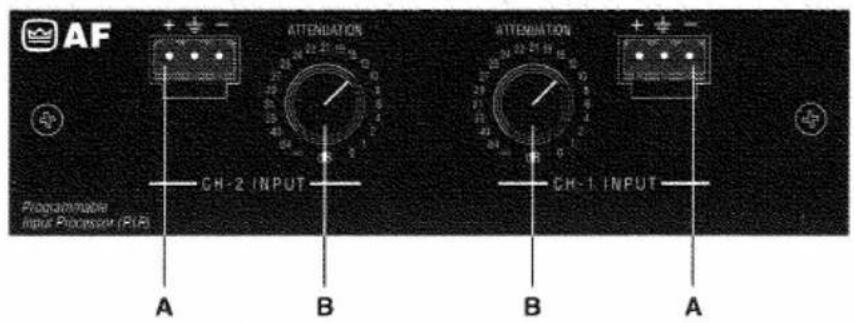
Fig. 1.1 Front View

Fig. 1.2 Bottom View
1 Welcome
Thank you for purchasing the Crown P.I.P.-AF (Attenuator and Eilter) accessory. P.I.P. ® modules are designed to quickly install in the rear panel of Crown Com-Tech, ® Macro-Tech ® or Macro Reference ™ series amplifiers. P.I.P. stands for “Programmable Input Processor.” Their versatile features expand the capabilities of your amplifier and enable you to customize it for your specific needs.
When you unpack you should find:
P.I.P.-AF Module
Two 8-32 Phillips Machine Screws Two Lock Washers
Two Quick-Disconnect Barrier Blocks This Owner's Manual
Features
☐ Active balanced inputs.
☐ RFI filter which attenuates unwanted ultrasonic frequencies. The RFI filter is a 12 dB/octave (2nd order), Bessel-tuned low-pass filter with a 3 dB roll-off point at 30 kHz.
☐ Defeatable subsonic/bass filter with 50 Hz roll-off.
☐ Detented 21-step attenuators provide repeatable input signal control.
☐ Quick-connect barrier block connectors provide for greater wiring flexibility and easier installation.
Facilities
A. Balanced Input
With these special quick-connect barrier-block connectors (Figure 1.1), it's quick and easy to attach each input cable with just three screws. Once the cable is attached, the connector can be quickly unplugged and, if desired, moved to a different amplifier.
B. Input Attenuator
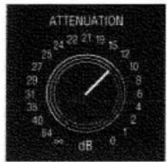
Each channel has a detented attenuator (Figure 1.1) which provides repeatable level adjustment. The attenuator controls have 21 detented steps that "click" into place for easy operation. The controls are labeled to indicate the input attenuation in dB for each position.
C. High-pass Jumper
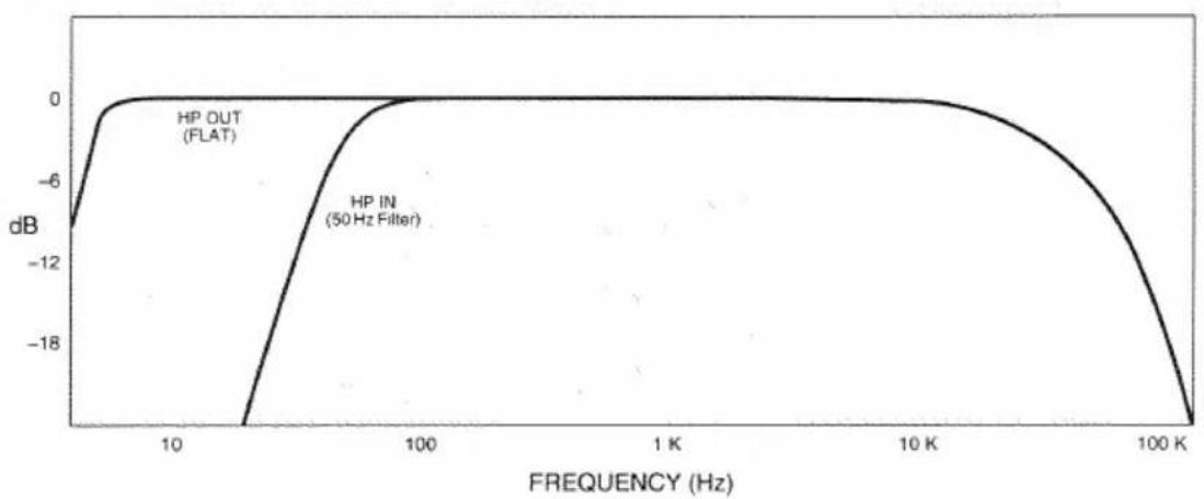
The P.I.P.-AF incorporates a 50 Hz fixed frequency high-pass filter with a slope of 18 dB/octave. This filter can be bypassed by moving the high-pass jumper to the OUT position (Figure 1.2).
2 Installation
Before installing this P.I.P. module, you should decide whether or not the 50 Hz high-pass filter will be needed. Each channel has an independent HP jumper that is used to enable or disable its high-pass filter. To enable the filter for a particular channel, move the corresponding HP jumper to the IN position. To disable a channel's filter, move its jumper to the OUT position.
Note: The RFI filters are always on and cannot be switched off.
Now you are ready to install the P.I.P. in the amplifier.
IMPORTANT: Before connecting this or any P.I.P. to your amplifier, turn its level controls down, turn it off and remove the AC power. Even though the amplifier is off, there could still be enough energy in the circuitry to cause electric shock. You only need a phillips screw-driver to connect the P.I.P.-AF.
- Turn down the amplifier's level controls (full counterclockwise), turn off the amplifier and unplug it from the AC power source.
- Remove the existing P.I.P. module (two screws) and pull straight out with firm pressure.
- Align the edge connector of the P.I.P. with the card rails (Figure 2.1).
- Firmly push the P.I.P. in until it is seated against the mounting bracket.
- Secure the P.I.P.-AF with the two included screws and lock washers. The lock washers are important because they ground the P.I.P. to the chassis of the amplifier.

Fig. 2.1 P.I.P. Installation
line
| FREQUENCY (Hz) | HP OUT (FLAT) | HP IN (50 Hz Filter) | | -------------- | ------------- | -------------------- | | 10 | -12 | -18 | | 100 | 0 | 0 | | 1K | 0 | 0 | | 10K | 0 | 0 | | 100K | -18 | -18 |Fig. 2.2 P.I.P.-AF Frequency Response
- Turn the P.I.P.-AF attenuators fully counterclockwise (maximum attenuation).
- Plug in the amplifier and turn it on.
- Turn the detented level controls of the P.I.P.-AF fully clockwise (no attenuation).
- Set the amplifier's level controls to the maximum desired output.
- Trim the output levels using the attenuator controls on the P.I.P.-AF.
In many audio systems, amplifier output level controls must be secured to prevent tampering. For Com-Tech amplifiers, level controls can be secured by installing the plexiglass security covers included with each unit. For Macro-Tech amplifiers, level control shaft lock kits can be installed which are available from Crown.
Remember: Crown is not liable for any damage resulting from overdriving other components in your sound system.

crown
P.I.P.-AF
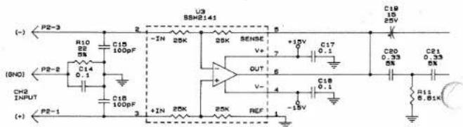
Only one channel shown
P.I.P.-AF

crown
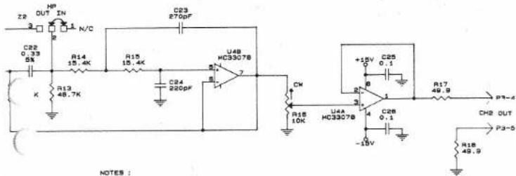
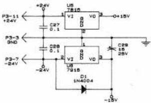
NOTES :
1. ALL RESISTORS ARE IN OHMS, 1/4N, 1% UNLESS OTHERWISE SPECIFIED.
2. ALL CAPACITORS ARE IN MICROFARADS UNLESS OTHERWISE SPECIFIED.
3. P3 PINS 6, 8-10, AND 12-22 ARE NOT USED.
4. HP FILTER IS SET FOR 80HZ.
5. ULTRASONIC FILTER IS SET FOR 33KHZ.
J0610-6
Notes:
- All resistors are in ohms, 0.25W, 1%, unless specified otherwise.
- All capacitors are in microfarads unless specified otherwise.
3 Specifications
Note: All specifications are referenced to a 0.775 V input signal.
Signal-to-Noise: Greater than 85 dB (equivalent input noise) from 20 Hz to 20 kHz.
Common Mode Rejection: Greater than 90 dB at 60 Hz; greater than 60 dB at 20 kHz.
Crosstalk: -60 dB at 1 kHz.
Input Impedance: Nominally 50 K ohms balanced and 25 K ohms unbalanced.
Recommended Source Impedance: 10 K ohms or less.
Maximum Input Level: +20 dB at 1 kHz.
Nominal Gain: Unity.
Frequency Response: ±1 dB from 20 Hz to 10 kHz (HP OUT). High-pass (subsonic/bass) filter has a -3 dB roll-off point of 50 Hz (see Figure 2.2).
The response is also affected by a permanent RFI filter with a -3 dB roll-off at 30 kHz.
Attenuation: 21-step attenuator for each channel:
Dimensions: 638 × 178 × 378 in (16.2 × 4.8 × 9.8 cm) .
Weight: 7 ounces (196 g).

crown®
DISTRIBUTED IN NORTH AMERICA AS CROWN. EXPORTED AS AMCRON.
CROWN/AMCRON
P.O. Box 1000, Elkhart, IN 46515-1000
Telephone: 219-294-8200; 1-800-342-6939 (U.S.A.)
Fax: 219-294-8301
Brand : CROWN
Model : P.I.P.-AF
Category : Audio processor