
ICMTS 50 - Motorized valve DANFOSS - Free user manual and instructions
Find the device manual for free ICMTS 50 DANFOSS in PDF.


| Product Type | Motorized Valve |
| Model | ICMTS 50 |
| Brand | Danfoss |
| Connection Size | DN 50 (2 inches) |
| Operating Pressure | Max 25 bar |
| Fluid Temperature | -10°C to 120°C |
| Power Supply | 24 V DC ±10% |
| Power Consumption | 15 W |
| Control Signal | 0-10 V or 4-20 mA |
| Stroke Length | 20 mm |
| Closing Force | 500 N |
| Protection Class | IP54 |
| Materials | Body: Brass, Seal: PTFE |
| Dimensions (L x W x H) | 200 mm x 100 mm x 150 mm |
| Weight | 2.5 kg |
| Main Functions | On/off, modulating control |
| Maintenance | Clean housing with dry cloth; check cable connections periodically |
| Safety Features | Thermal overload protection, IP54 enclosure |
| Spare Parts | Seal kit, cable gland |
| Repairability | Field-replaceable actuator and seal |
| General Information | For use in HVAC and refrigeration systems |
Frequently Asked Questions - ICMTS 50 DANFOSS
User questions about ICMTS 50 DANFOSS
0 question about this device. Answer the ones you know or ask your own.
Ask a new question about this device
Download the instructions for your Motorized valve in PDF format for free! Find your manual ICMTS 50 - DANFOSS and take your electronic device back in hand. On this page are published all the documents necessary for the use of your device. ICMTS 50 by DANFOSS.
USER MANUAL ICMTS 50 DANFOSS
Motor operated valve
Type ICMTS 50/80 with actuator, type ICAD 600A-TS

027R9685
Installation
natural_image
Technical line drawing of seven mechanical pipe fittings arranged in a 2x2 grid (no text or symbols)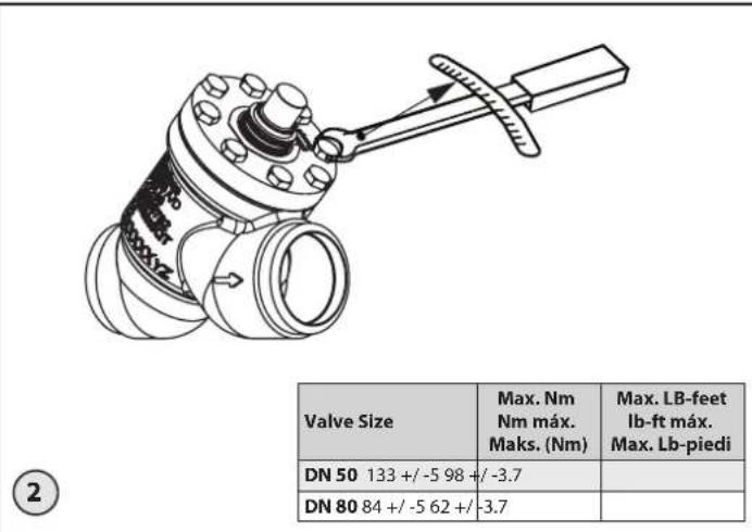
natural_image
Technical line drawing of mechanical assembly with three stages: top view, middle view, and bottom view (no text or symbols)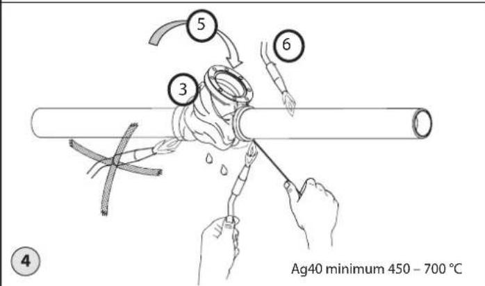
Info for UK customers only : Danfoss Ltd., 22 Wycombe End, HP9 1NB, GB
027R9685
Maintenance
ENGLISH
Installation
Refrigerants
The ICMTS 50/80 is specifically designed for high pressure R744 applications. The valve is only recommended for use in closed circuits. For further information, please contact Danfoss.
Temperature range
Allowable TS: -60/+150 °C (-76/+302 °F)
Operation: -40/+50 °C (-40/+122 °F)
Ambient: -30/+50 °C (-22/+122 °F)
In systems with continuous media temperatures above +50 °C (+122 °F) Danfoss recommend to inspect the valve annually and replace the PTFE valve seat if needed.
Pressure
The valves are designed for a max. working pressure of 140 bar (2030 psig).
Function
ICMTS is a balanced valve which remains in its position. The return function must be provided by use of the actuator.
The ICMTS can be used in suction, liquid, hot gas and liquid/vapour lines. The ICMTS regulates the flow of the medium by modulation or the on/off function, depending on the control impulse to the actuator. Refer to the technical leaflet for details on design and regarding selections. The ICMTS valve is designed for use with the ICAD 600A-TS actuator from Danfoss.
The ICAD 600A-TS actuator on the ICMTS ensures compatibility with the regulators provided by Danfoss plus a range of other controllers, especially PLC controllers. A control signal from a Danfoss controller or PLC will activate the ICAD 600A-TS motor and, through a magnetic coupling, rotate the spindle in the ICMTS to make the cone change opening degree.
Valve sizes
ICMTS is available in sizes from
• ICMTS 50-A (K _v : 9,0 m ^3 /h)
• ICMTS 80-A ( K_v : 18 m ^3 /h)
• ICMTS 80-B ( K_v : 27 m ^3 /h)
Installation
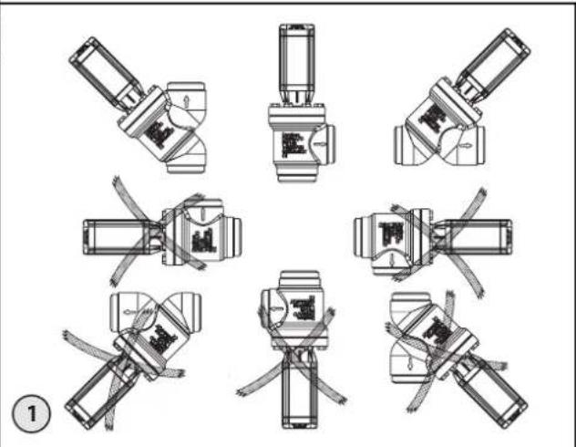
ICMTS + ICAD 600A-TS can be installed in pipelines with the actuator pointing upwards (fig. 1) or in 45 °C angle to vertical up.
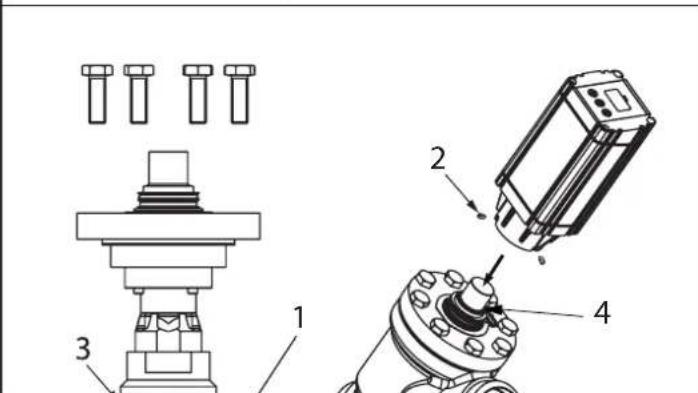
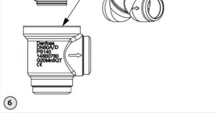
The motor can be mounted in any position before locking it with the 3 Allen screws (fig. 6, pos. 2).
The ICMTS valve must be installed with the arrow in the direction of flow. When installing an ICMTS, refrigerant must not be allowed to escape, and dirt must not be allowed to enter the valve. The valve is designed to withstand a high internal pressure. However, the piping system should be designed to avoid liquid traps and reduce the risk of hydraulic pressure caused by thermal expansion. It must be ensured that the valve is protected from pressure transients like "liquid hammer" in the system.
ICMTS valves must not be mounted in systems where the outlet side of the valve is open to atmosphere. The outlet side of the valve must always be connected to the system or properly capped off, such as the case with a welded-on end plate.
Welding or brazing (fig. 3 & 4)
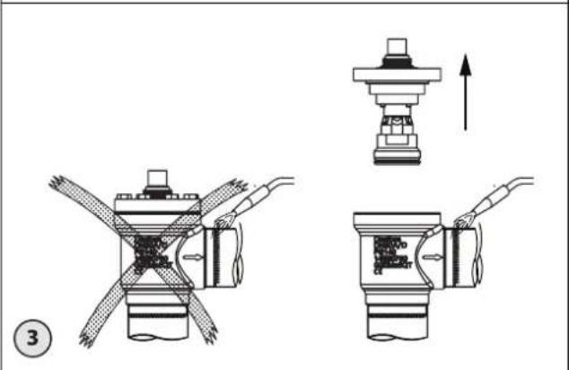
The top cover, complete with function module, should be removed before welding or brazing to prevent damage to O-rings and Teflon (PTFE) in the function module and to avoid getting welding debris in the module. Be careful not to damage the sealings and sealing surfaces and make sure the complete bonnet is protected from dirt and water while removed.
The internal surfaces and weld connections of the enclosed ICMTS valve have been applied with an anti-corrosion treatment. To maintain the effectiveness of this anti-corrosion treatment, it is important to ensure that the valve is disassembled just prior to commencing the welding / brazing process. In the event that the function modules are to be left disassembled for any length of time, please ensure that the function modules are further protected by placing in a polyethylene bag or by applying a rust protection agent (e.g. refrigeration oil) on the surfaces.
Only materials and welding methods, compatible with the valve body material, must be applied. The valve should be cleaned internally to remove welding debris on completion of welding and before the valve is reassembled.
Avoid welding debris and dirt in the valve body and the function module. The valve body must be free from stresses (external loads) after installation.
Brazing (fig. 4)
When brazing, Danfoss recommends using Ag40 minimum 450 – 700 °C filler or better which are suitable for the working pressure, and following procedure observed (fig. 4):
-
Remove top cover/insert
-
Clean connections with cleaning agent
-
Wrap around wet cloth
-
Apply flux on piping ends
-
Apply inert gas internal
-
Heat up piping
-
Braze with recommended brazing material and within temperature range specified
-
Remove residual flux
Manual operation
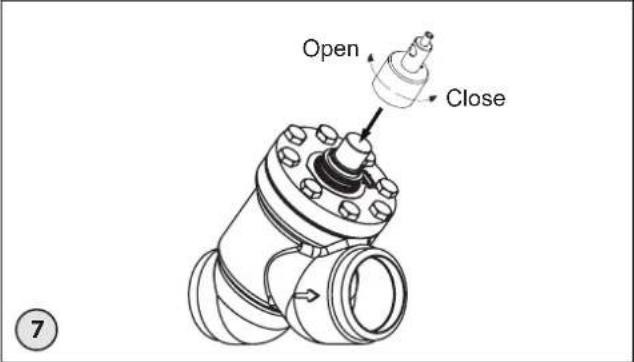
A magnetic coupling can be used to rotate the spindle manually if the actuator has been removed. To make use of the manual operation, a multi-function tool (optional) is used (see fig. 7). The code number for the multi-function tool is 027H0181.
Manual operation is also possible with the actuator mounted on the valve and the power supply connected to the actuator. If the signal connections are wired to the actuator, it is possible to use the manual operation function built into the actuator electronics which allows the motor to step in 1% increments meaning that 100 steps will correspond to a fully open valve. Please refer to the separate instruction manual on ICAD to address the manual function.
Insulation
Insulating the valve and its actuator is only necessary if an energy consideration in the plant requires this. Regarding the function of the ICMTS + ICAD 600A-TS, no insulation is necessary when kept inside temperature limits.
Surface treatment and identification
The ICMTS valves are surface treated from factory. If further corrosion protection is required, the valves can be painted.
Note: Magnet coupling must be protected.
Precise identification of the valve is made via the ID plate. After welding, the external surface around the connections of the valve body must be protected to prevent against corrosion with a suitable coating. When repainting the valve, it is recommended to protect the ID plate.
Assembly
Remove welding debris and any dirt from pipes and valve body before assembly. Use the manual magnetic tool (fig. 7) to achieve rotation through the top. A small amount of refrigeration oil on both O-rings can make the insert easier to install into the valve body.
Tightening
Tighten the bonnet with a torque wrench, to the values indicated in the table (fig. 2). Please note that the table (fig. 2) containing maximum torque must be adhered to and never exceeded.
ICAD 600-TS configuration
To work with ICMTS 50/80 the ICAD parameter i26 Valve configuration shall be set to 3 (ICM 32).
Maintenance
Service
A precise service schedule cannot be given for the valve as service intervals will depend on operating conditions, i.e. how often the valve operates and the amount of impurities and dirt the system carries.
The ICMTS valves are easy to dismantle, and all parts inside can be replaced by changing the function module.
Do not open the valve while the valve is still under pressure.
Be aware that the valve can be under pressure from both sides and that the manual magnet tool (fig. 7) can be used to open the seat to equalize pressure internally before removing the top cover.
Before servicing the valve, isolate it from the system. Drain CO_2 liquid e.g. to above 5,2 bar to prevent large formation of dry ice before evacuation to zero pressure. Check for refrigerant pressure before unscrewing and removing the top cover. If the flat gasket (fig. 6, pos. 1) or the O-ring sealing (fig. 6, pos. 3) has been damaged, it must be replaced using the ICMTS inspection kit.
Replacement of the function module
- Remove the old module.
- Oil the O-rings (fig. 6, pos. 3 & 4) on the new module with a small amount of refrigeration oil.

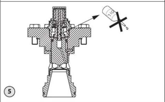
pindle inside the valve must not eased or oiled (fig. 5).
Repair of the function module
The ICMTS 50/80 seat PTFE sealing can be replaced using Danfoss repair kit.
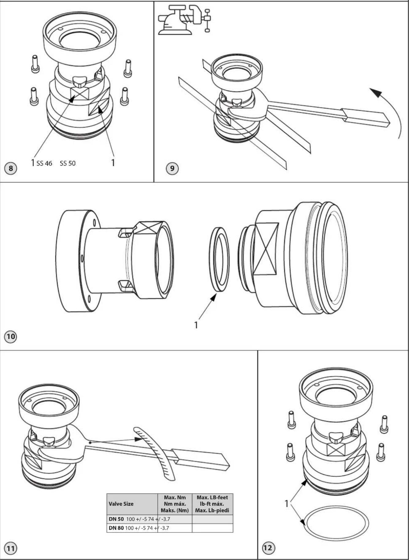
- Unscrew the 4 M4 Allen screws (fig. 8)
-
Fasten the cylindrical assembly lower part in a vise at the flat surfaces and unscrew the upper part with a wrench at the flat surfaces (fig. 8, pos. 1 & fig. 9)
-
Disassemble the assembly into two parts (fig. 10)
- Replace the PTFE sealing with the one from the repair kit (fig. 10, pos. 1)
- Reassemble the 2 parts and tighten the assembly by use of vise and wrench to the torque indicated in fig. 11
- Clean and reassemble the entire insert with the 4 M4 Allen screws tightened to torque 5 Nm (3.7 lb-feet) (fig. 12)
- Add refrigeration oil to the new O-ring and replace the O-ring (fig. 12, pos. 1)
- Replace the Flat gasket (fig.6, pos. 1) and assemble the valve to the torque indicated in fig. 2
The piston is not subject for replacement, but it may be cleaned including the ∅2.5 mm equalization hole.
The spindle inside the valve must not be greased or oiled (fig. 5).
In case the piston has been damaged, the entire top module shall be replaced.
Charge CO2 gas to above 5,2 bar to prevent large formation of dry ice when charging with CO2 liquid or equalizing with system pressure.
Use only original Danfoss parts, including O-rings and gaskets for replacement. Materials of new parts are certified for the relevant refrigerant.
In cases of doubt, please contact Danfoss. Drawings are only for illustration, not for dimensioning or construction. Danfoss accepts no responsibility for errors and omissions. Danfoss Industrial Refrigeration reserves the right to make changes to products and specifications without prior notice.
Danfoss A/S
Climate Solutions · danfoss.com · +45 7488 2222
Any information, including, but not limited to information on selection of product, its application or use, product design, weight, dimensions, capacity or any other technical data in product manuals, catalogues descriptions, advertisements, etc. and whether made available in writing, orally, electronically, online or via download, shall be considered informative, and is only binding if and to the extent, explicit reference is made in a quotation or order confirmation. Danfoss cannot accept any responsibility for possible errors in catalogues, brochures, videos and other material. Danfoss reserves the right to alter its products without notice. This also applies to products ordered but not delivered provided that such alterations can be made without changes to form, fit or function of the product. All trademarks in this material are property of Danfoss A/S or Danfoss group companies. Danfoss and the Danfoss logo are trademarks of Danfoss A/S. All rights reserved.
- Motor operated valve
- ENGLISH
- Installation
- Refrigerants
- Temperature range
- Pressure
- Function
- Valve sizes
- Welding or brazing (fig. 3 & 4)
- Brazing (fig. 4)
- Manual operation
- Insulation
- Surface treatment and identification
- Assembly
- Tightening
- ICAD 600-TS configuration
- Maintenance
- Service
- Replacement of the function module
- Repair of the function module
- Danfoss A/S
Brand : DANFOSS
Model : ICMTS 50
Category : Motorized valve