POE-171S - Network switch Planet - Free user manual and instructions
Find the device manual for free POE-171S Planet in PDF.


| Product Type | PoE Network Switch |
| Model | POE-171S |
| Brand | Planet |
| Ports | 8 x 10/100Mbps PoE ports |
| PoE Standard | IEEE 802.3af/at |
| PoE Power Budget | Up to 120W total |
| Switching Capacity | 1.6 Gbps |
| MAC Address Table | 1K entries |
| Dimensions (W x D x H) | 200 x 120 x 44 mm (7.9 x 4.7 x 1.7 in) |
| Weight | 0.8 kg (1.76 lbs) |
| Power Supply | External AC adapter, 48V DC |
| Input Voltage | 100-240V AC, 50-60Hz |
| Power Consumption | Max 130W (with PoE load) |
| Operating Temperature | 0°C to 40°C (32°F to 104°F) |
| Storage Temperature | -10°C to 70°C (14°F to 158°F) |
| Humidity | 10% to 90% non-condensing |
| LED Indicators | Power, PoE, Link/Activity per port |
| Mounting | Desktop or wall-mountable |
| Cooling | Fanless design |
| Safety | CE, FCC compliant |
| Warranty | 2 years |
| Package Contents | Switch, power adapter, user manual |
Frequently Asked Questions - POE-171S Planet
User questions about POE-171S Planet
0 question about this device. Answer the ones you know or ask your own.
Ask a new question about this device
Download the instructions for your Network switch in PDF format for free! Find your manual POE-171S - Planet and take your electronic device back in hand. On this page are published all the documents necessary for the use of your device. POE-171S by Planet.
USER MANUAL POE-171S Planet
Single-Port 10/100/1000Mbps
Ultra PoE Injector (60 Watts)
POE-171
Single-Port 10/100/1000Mbps
Ultra PoE Splitter (12V/19V/24V)
POE-171S
User's Manual
Version 1.0
Trademarks
Copyright © PLANET Technology Corp. 2013.
Contents are subject to revision without prior notice.
PLANET is a registered trademark of PLANET Technology Corp. All other trademarks belong to their respective owners.
Disclaimer
PLANET Technology does not warrant that the hardware will work properly in all environments and applications, and makes no warranty and representation, either implied or expressed, with respect to the quality, performance, merchantability, or fitness for a particular purpose.
PLANET has made every effort to ensure that this User's Manual is accurate; PLANET disclaims liability for any inaccuracies or omissions that may have occurred.
Information in this User's Manual is subject to change without notice and does not represent a commitment on the part of PLANET. PLANET assumes no responsibility for any inaccuracies that may be contained in this User's Manual. PLANET makes no commitment to update or keep current the information in this User's Manual, and reserves the right to make improvements to this User's Manual and/or to the products described in this User's Manual, at any time without notice. If you find information in this manual that is incorrect, misleading, or incomplete, we would appreciate your comments and suggestions.
FCC Warning
This equipment has been tested and found to comply with the limits for a Class A digital device, pursuant to Part 15 of the FCC Rules. These limits are designed to provide reasonable protection against harmful interference when the equipment is operated in a commercial environment. This equipment generates, uses, and can radiate radio frequency energy and, if not installed and used in accordance with the Instruction manual, may cause harmful interference to radio communications. Operation of this equipment in a residential area is likely to cause harmful
interference in which case the user will be required to correct the interference at his own expense.
CE Mark Warning
This is a Class A product. In a domestic environment, this product may cause radio interference, in which case the user may be required to take adequate measures.
Energy Saving Note of the Device
This power required device does not support Standby mode operation.
For energy saving, please remove the power cable to disconnect the device from the power circuit.
Without removing power cable, the device will still consuming power from the power source. In view of Saving the Energy and reducing the unnecessary power consumption, it is strongly suggested to remove the power connection for the device if this device is not intended to be active.
WEEE Warning
To avoid the potential effects on the environment and human health as a result of the presence of hazardous substances in electrical and electronic equipment, end users of electrical and electronic equipment should understand the meaning of the crossed-out wheeled bin symbol. Do not dispose of WEEE as unsorted municipal waste; WEEE should be collected separately.
Revision
PLANET Single-Port 10/100/1000Mbps Ultra PoE Injector User's Manual
For Model: POE-171 and POE-171S
Revision: 1.1 (August, 2013)
Part No.: 2350-AF0430-001
Table of Contents
- Package Contents .... 5
- Product Features.... 6
- Product Specifications .... 8
- Product Outlook ...... 12
- Hardware Installation 14
5.1 Before Installation 14
5.2 The POE-171 Installation 14
5.3 The POE-171 and POE-171S Installation 16
5.4 The POE-171 and POE-E201 Installation 17 - Customer Support 19
1. Package Contents
Thank you for purchasing PLANET Single-Port 10/100/1000Mbps POE-171 or POE-171S.
| Model LAN Port Speed PoE | Standard PoE Budget | ||
| POE-171 | 10/100/1000Mbps IE | EE 802.3at/af 60 watts | |
| Model LAN Port Speed PoE | Standard DC Out | ||
| POE-171S | 10/100/1000Mbps IE | EE 802.3at/af 12V | /19V/24V |
Please unpack the box of the POE-171 or POE-171S carefully, and the box should contain the following items:
[POE-171]
● The Single-Port 10/100/1000Mbps ultra PoE injector x 1
- User's manual x 1
- 65W power adaptor x 1
[POE-171S]
● The Single-Port 10/100/1000Mbps ultra PoE splitter x 1
- User's manual x 1
- DC plug cable x 2
- 15cm RJ45 cable x 1
If any of these are missing or damaged, please contact your dealer immediately; if possible, retain the carton including the original packing material, and use them again to repack the product in case there is a need to return it to us for repair.
2. Product Features
[POE-171]
■ Interface
2-Port RJ-45 interfaces ●
✨ 1-Port Data + Power output
✨ 1-Port Data input
1 DC 52\~56V input power socket ●
■ Power over Ethernet
Ultra Power over Ethernet End-Span / Mid-Span PSE ●
IEEE 802.3at PoE compliant ●
Backward compatible with IEEE 802.3af PD device ●
Supports PoE Power up to 60 watts for PoE port ●
Auto-detection of PoE IEEE 802.3at/af equipment and ● devices from being damaged by incorrect installation
●Remote power feeding up to 100m
[POE-171S]
■ Interface
2-Port RJ-45 interfaces ●
✨ 1-Port Data + Power input
✨ 1-Port Data output
●1-Port DC output power socket
●1 DC 12V/19V/24V DIP switch
■ Power over Ethernet
- Complies with ultra Power over Ethernet End-Span/Mid-Span PSE
IEEE 802.3at PoE compliant ●
Splits the 56V DC power over RJ-45 Ethernet cable into DC ● 12V/19V/24V output
Distance up to 100 meters ●
IEEE802.3af Injector devices compatible ●
Hardware
Metal case ●
LED indicators for Power LED and PoE In-use LED ●
■ Standard Compliance
IEEE 802.3 10Base-T ●
IEEE 802.3u 100Base-TX ●
IEEE 802.3ab 1000Base-T ●
IEEE 802.3at High Power over Ethernet ●
IEEE 802.3af Power over Ethernet ●
FCC Part 15 Class A, CE ●

Note
PSE (Power Sourcing Equipment) is a device (switch, or hub for instance) that will provide power in a PoE setup. Maximum allowed continuous output power per such device in IEEE 802.3af is 15.4W, and in IEEE 802.3at is 30W.
PD (Powered Device) is a PoE-enabled terminal by PSE and thus consumes energy, such as PoE IP Phones, PoE IP cameras, PoE wireless access points, etc.
3. Product Specifications
| Product POE-171 | ||
| Hardware Specifications | ||
| Interface | LAN Ethernet 1 x | RJ-45 STP, "Data" Input Port |
| Ethernet+DC (PoE) | 1 x RJ-45 STP, Data + Power" Output Port | |
| Power 1 x DC 56V | Input socket | |
| Network Cable | Ultra PoE (60W) | 4-Pair UTP Cat. 3, 4, 5, up to 100m (328ft) |
| 802.3af/at PoE (15W / 30W) | 2-Pair UTP Cat. 3, 4, 5, up to 100m (328ft) | |
| LED Indicator | System: Power x 1 (Green)PoE Port: PoE In-use x 2 (Green) | |
| Data Rate 10/100/1000Mbps | ||
| Dimensions (W x D x H) 94 x | 70.3 x 26.2 mm | |
| Weight 237g | ||
| Unit Output Voltage DC 56V, | 1.16 A | |
| Power Requirements 100-240V AC, 50/60Hz, 1.5A | ||
| Power Consumption 60 Watts max. | ||
| Number of devices can be powered | 1 | |
| Operating Temperature 0 ~ 50 degrees C | ||
| Storage Temperature -10 ~ 70 degrees C | ||
| Operating Humidity | 5 ~ 90%, Relative Humidity, non-condensing | |
| Storage Humidity | 5 ~ 90%, Relative Humidity, non-condensing | |
| Power over Ethernet | ||
| PoE Standard | Ultra PoE over 4-pair UTP, IEEE 802.3at High Power over Ethernet End-Span / Mid-Span PSE | |
| PoE Power Output Budget DC | 56V / 60 Watts | |
| PoE Power Supply Type End-Span + Mid-Span | ||
| Power Pin Assignment | Pair 1 End-Span: 1/2(-), 3/6(+) Pair 2 Mid-Span: 4/5(+), 7/8(-) | |
| Standards Conformance | ||
| Standards Compliance | IEEE 802.3 10Base-T Ethernet IEEE 802.3u 100Base-TX Fast Ethernet IEEE 802.3ab 1000Base-T Gigabit Ethernet IEEE 802.3at High Power over Ethernet IEEE 802.3af Power over Ethernet | |
| Regulation Compliance FCC Part 15 Class A, CE | ||
| Product POE-171S | ||
| Hardware Specifications | ||
| Interface | Ethernet | 1 x RJ-45 STP, Ethernet data output port |
| PoE In | 1 x RJ-45 STP, PoE power input port | |
| Power socket 1 x | DC out power socket | |
| Network Cable | Ultra PoE (60W) | 4-Pair UTP Cat. 3, 4, 5, up to 100m (328ft) |
| 802.3af/at PoE (15W / 30W) | 2-Pair UTP Cat. 3, 4, 5, up to 100m (328ft) | |
| LED Indicator | System: Power x 1 (Green) PoE In-use x 2 (Green) | |
| Data Rate 10/100/1000Mbps | ||
| Dimensions (W x D x H) 94 x 70.3 x 26.2 mm | ||
| Weight 300g | ||
| Unit Output Current (at 56V Input) | 4.2A@12V DC2.6A@19V DC2.1A@24V DC | |
| Power Consumption 54 watts | max. | |
| Number of devices can be powered | 1 | |
| Operating Temperature 0 ~ 50 degrees C | ||
| Storage Temperature -10 ~ 70 degrees C | ||
| Operating Humidity | 5 ~ 90%, Relative Humidity, non-condensing | |
| Storage Humidity | 5 ~ 90%, Relative Humidity, non-condensing | |
| Power over Ethernet | ||
| PoE Standard | IEEE 802.3at High Power over Ethernet End-Span / Mid-Span PD | |
| PoE Power Output Budget DC | 56V / 50 Watts | |
| PoE Power Supply Type End-Span / Mid-Span | ||
| Power Pin Assignment 1/2(-), 3/6(+) / 4/5(+), 7/8(-) | ||
| Standards Conformance | ||
| Standards Compliance | IEEE 802.3 10Base-T EthernetIEEE 802.3u 100Base-TX Fast EthernetIEEE 802.3ab 1000Base-T Gigabit EthernetIEEE 802.3at High Power over EthernetIEEE 802.3af Power over Ethernet | |
| Regulation Compliance FCC Part 15 Class A, CE | ||
4. Product Outlook
Figure 1: shows overview of POE-171.
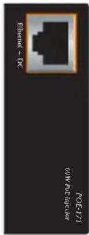
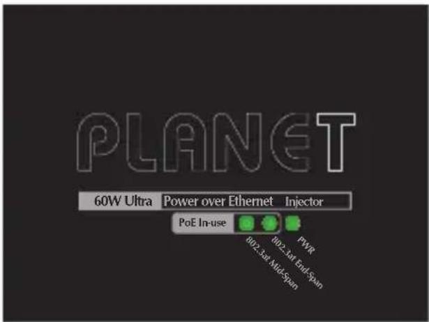
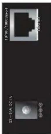
Figure 1: POE-171 Outlook
Figure 2: shows overview of POE-171S.
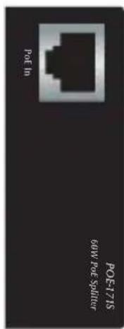
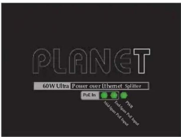
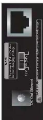
Figure 2: POE-171S Outlook
POE-171 LED Indicators
| LED Color Function | ||
| PWR Green | Lights to indicate the ultra PoE injector has power. | |
| 802.3at End-Span | Green | Lights to indicate the ultra PoE injector is working in End-Span mode and offers up to 30 watts of power. |
| 802.3at Mid-Span | Green | Lights to indicate the ultra PoE injector is working in Mid-Span mode and offers up to 30 watts of power. |
POE-171S LED Indicators
| LED Color Function | ||
| PWR Green | Lights to indicate the ultra PoE splitter has power. | |
| End-Span PoE Input | Green | Lights to indicate the ultra PoE splitter is working in End-span mode |
| Mid-Span PoE Input | Green | Lights to indicate the ultra PoE splitter is working in Mid-span mode |
5. Hardware Installation
The following section describes the hardware features of PoE-171 and POE-171S. Before connecting any network device to them, please read this chapter carefully.
Please refer to following sections for detailed information about POE-171
5.1 Before Installation
Before your installation, it is recommended to check your network environment. If there is any IEEE 802.3at device that needs higher power to be powered on and works normally, the POE-171 provides you with a way out to supply power to this Ethernet device conveniently and easily. The POE-171 is equipped with a power adaptor which is 100-240V AC input and injects DC 56V power into the pin of the twisted pair cable (pair 1/2 [-], 3/6 [+] and pair 4/5[+], 7/8[-]).
If there is difficulty in finding a power socket for AC-DC adapter of your non-PoE IEEE 802.3at networked device, the POE-171 and POE-171S (Ultra PoE Splitter) provide you with a way out to supply DC power to this Ethernet device conveniently and easily.

The POE-171 and POE-171S can be installed in a pair. However, the use of third-party device is allowed if the device complies with IEEE 802.3at Power over Ethernet.
5.2 The POE-171 Installation
-
Connect the AC power adaptor to "52-56V DC IN" of POE-171; the "PWR" LED will be steadily on.
-
Connect a standard Ethernet cable from an Ethernet switch or PC workstation to "Ethernet" port of POE-171.
-
Connect the long cable to "Ethernet+DC" port.
-
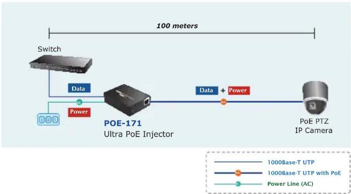
Connect with IEEE 802.3at/802.3af devices. Due to the capability of IEEE 802.3at/802.3af Power over Ethernet, the POE-171 can directly connect with any IEEE 802.3at/802.3af end-nodes, such as PTZ (Pan, Tilt & Zoom) network cameras, PTZ speed dome, color touch-screen, Voice over IP (VoIP) telephones and multi-channel wireless LAN access points which support IEEE 802.3at/802.3af In-line Power over Ethernet port. The screen in Figure 3 appears.
flowchart
graph LR
    A["Switch"] -->|Data| B["POE-171 Ultra PoE Injector"]
    B -->|Data + Power| C["PoE PTZ IP Camera"]
    D["888"] -->|Power| B
    style A fill:#f9f,stroke:#333
    style B fill:#ccf,stroke:#333
    style C fill:#cfc,stroke:#333
Figure 3: Connecting architecture with IEEE 802.3at/802.3af devices
Once POE-171 detects the existence of an IEEE 802.3at/802.3af device, the PoE In-use LED indicator will be steadily on to show it is providing power.

Note
-
Since the PoE port of PoE-171 supports 52-56V DC PoE power output, please check and assure the powered device (PD) accepts DC power range of 52-56V DC. Otherwise, it will damage the powered device (PD).
-
If the connected device is not fully complied with IEEE 802.3at/802.3af Power over Ethernet or in-line power device, the LED indicator of POE-171 will not be steadily on.
5.3 The POE-171 and POE-171S Installation

Note
Please turn off POE-171S before you switch DC power output mode.
-
Adjust proper DC power output and connect DC plug from "DC OUT" of POE-171S to remote device.
-
Connect the power adaptor to "52-56V DC IN" of POE-171; the "PWR" LED will be steadily on.
-
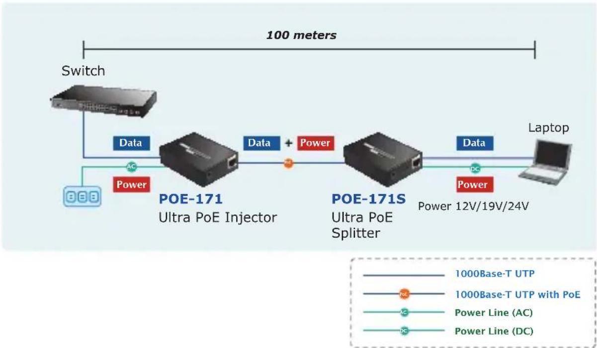
Connect a standard Ethernet cable from "Ethernet+DC" port of POE-171 to "PoE In" port of POE-171S. The "802.3at End-Span" and "802.3at Mid-Span" LED of POE-171 and POE-171S will light up continuously.
-
Connect a standard Ethernet cable from an Ethernet switch or PC workstation to "Ethernet" port of POE-171.
-
Connect a standard Ethernet cable from "Ethernet" port of POE-171S to the remote Ethernet device.
-
Turn on the remote device and its power LED indicator will remain on.
flowchart
graph LR
    A["Switch"] --> B["Data"]
    B --> C["POE-171 Ultra PoE Injector"]
    C --> D["Data + Power"]
    D --> E["POE-171S Ultra PoE Splitter"]
    E --> F["Data"]
    F --> G["Laptop"]
    style A fill:#f9f,stroke:#333
    style G fill:#bbf,stroke:#333
    note right of C: "100 meters"
    note right of E: "Power 12V/19V/24V"
    note right of F: "Power 12V/19V/24V"
    note right of G: "1000Base-T UTP with PoE"
    note_right_of_H["AC Power Line (AC)"]
    note_right_of_I["DC Power Line (DC)"]
Figure 4: Connected architecture over POE-171 and POE-171S

- According to IEEE 802.3at/802.3af Power over Ethernet, the POE-171 will not inject power to the cable if not connected to IEEE 802.3at/802.3af device.
- Please ensure the POE-171S output voltage is correct before applying power to remote device. The POE-171S provides DC12V/19V/24V power output.
5.4 The POE-171 and POE-E201 Installation
- Connect the power adaptor to "52-56V DC IN" of POE-171; the "PWR" LED will be steadily on.
- Connect a standard Ethernet cable from "Ethernet+DC" port of ultra PoE injector to the "IN" port of POE-E201.
- The ultra PoE injector delivers both Ethernet Data and PoE power over UTP cable to the POE-E201 and the POE In-use
LED of POE-171 and "PoE IN" LED of POE-E201 will light up continuously.
4 Connect the additional standard Ethernet cable that will be used for connecting to the remote powered device (PD) to the "OUT" port of POE-E201.
5. The "OUT" port is also the power injectors which transmit DC Voltage to the standard network cable and transfer data and power simultaneously between the POE-171 and PD.
6 Once POE-E201 detects the existence of an IEEE 802.3at/802.3af device, the "PoE OUT" LED indicator will be steadily ON to show it is providing power.
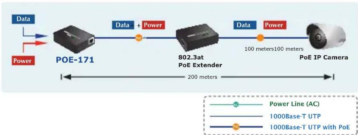
flowchart
graph LR
    A["Data"] --> B["POE-171"]
    C["Power"] --> B
    B --> D["Data + Power"]
    D --> E["802.3at PoE Extender"]
    E --> F["Data"]
    F --> G["PoE IP Camera"]
    G --> H["100 meters 100 meters"]
    style A fill:#4CAF50,stroke:#333
    style C fill:#FFA500,stroke:#333
    style B fill:#90EE90,stroke:#333
    style E fill:#ADD8E6,stroke:#333
    style F fill:#4CAF50,stroke:#333
    style G fill:#FFA500,stroke:#333
    style H fill:#4CAF50,stroke:#333
Figure 5: Connected architecture over POE-171 and POE-E201

- If the connected device is not fully complied with IEEE 802.3at/802.3af standard or in-line power device, the PoE OUT LED indicator of POE-E201 will not be steadily on.
- According to IEEE 802.3at/802.3af standard, the POE-E201 will not inject power to the cable if not connected to a standard IEEE 802.3at/802.3af device.
6. Customer Support
Thank you for purchasing PLANET products. You can browse our online FAQ resource at the PLANET Web site first to check if it could solve your issue. If you need more support information, please contact PLANET switch support team.
PLANET online FAQ :
http://www.planet.com.tw/en/support/faq.php?type=2
Switch support team mail address :
support_switch@planet.com.tw
Copyright © PLANET Technology Corp. 2013.
Contents are subject to revision without prior notice.
PLANET is a registered trademark of PLANET Technology Corp. All other trademarks belong to their respective owners.
EC Declaration of Conformity
For the following equipment:
*Type of Product : Single-Port 10/100/1000Mbps Ultra PoE Injector (60 Watts) Single-Port 10/100/1000Mbps Ultra PoE Splitter (12V/19V/24V)
*Model Number : POE-171 POE-171S
* Produced by: Manufacturer's Name : PLANET Technology Corp. Manufacturer's Address: 10F., No.96, Minquan Rd., Xindian Dist., New Taipei City 231, Taiwan (R.O.C.).
Is here with confirmed to comply with the requirements set out in the Council Directive on the Approximation of the Laws of the Member States relating to Electromagnetic Compatibility (2004/108/EC).
For the evaluation regarding the EMC, the following standards were applied:
EN 55022 (Class A:2006+A1:2007)
EN 55024 (2010)
IEC 61000-4-2 (2008)
IEC 61000-4-3 (2006+A1:2008+A2:2010)
IEC 61000-4-4 (2004+A1:2010)
IEC 61000-4-5 (2005)
IEC 61000-4-6 (2008)
IEC 61000-4-8 (2009)
IEC 61000-4-11 (2004)
Responsible for marking this declaration if the:
☑ Manufacturer ☐ Authorized representative established within the EU
Authorized representative established within the EU (if applicable):
Company Name: Planet Technology Corp.
Company Address: 10F., No.96, Minquan Rd., Xindian Dist., New Taipei City 231, Taiwan (R.O.C.)
Person responsible for making this declaration
Name, Surname Kent Kang
Position / Title : Product Manager
Taiwan
Place
22, July, 2013
Date
front fang
Legal Signature
- Single-Port 10/100/1000Mbps
- Ultra PoE Injector (60 Watts)
- POE-171
- Ultra PoE Splitter (12V/19V/24V)
- POE-171S
- Trademarks
- Disclaimer
- FCC Warning
- CE Mark Warning
- Energy Saving Note of the Device
- WEEE Warning
- Revision
- Table of Contents
- Package Contents
- [POE-171]
- [POE-171S]
- Product Features
- ■ Interface
- ■ Power over Ethernet
- Product Specifications
- Product Outlook
- Hardware Installation
- Before Installation
- The POE-171 Installation
- The POE-171 and POE-171S Installation
- The POE-171 and POE-E201 Installation
- Customer Support
- EC Declaration of Conformity
Brand : Planet
Model : POE-171S
Category : Network switch