IFGS-1022TF - Network switch Planet - Free user manual and instructions
Find the device manual for free IFGS-1022TF Planet in PDF.


User questions about IFGS-1022TF Planet
0 question about this device. Answer the ones you know or ask your own.
Ask a new question about this device
Download the instructions for your Network switch in PDF format for free! Find your manual IFGS-1022TF - Planet and take your electronic device back in hand. On this page are published all the documents necessary for the use of your device. IFGS-1022TF by Planet.
USER MANUAL IFGS-1022TF Planet
Industrial 8-Port 10/100TX +
2-Port Gigabit TP/SFP Combo Ethernet Switch
IFGS-1022TF
User's Manual
Table of Contents
- Package Contents.... 3
- Product Specifications.... 4
- Hardware Introduction....6
3.1 Switch Front Panel....6
3.2 LED Definition 7
3.3 Switch Upper Panel 8
3.4 Wiring the Power Inputs....8
3.5 Wiring the Fault Alarm Contact 9
- Installation ....10
4.1 DIN-rail Mounting Installation 10
4.2 Wall-mount Plate Mounting....10
4.3 Side Wall-mount Plate Mounting....11
4.4 Grounding the Device....11
Customer Support....12
1. Package Contents
Thank you for purchasing PLANET Industrial 8-Port 10/100TX + 2-Port Gigabit TP/SFP Combo Ethernet Switch, IFGS-1022TF. In the following sections, the term "Industrial Ethernet Switch" means the IFGS-1022TF.
Open the box of the Industrial Ethernet Switch and carefully unpack it. The box should contain the following items:
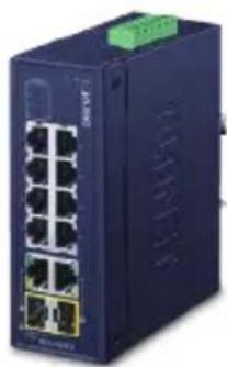
Industrial Ethernet Switch x 1 QR code sheet x 1
natural_image
Blue industrial network switch device with multiple Ethernet ports (no visible text or labels)
DIN-rail Kit Wall-mount Kit


natural_image
Two dark rectangular panels with four small white circular holes, no text or symbols visible.RJ45 Dust Cap x 10 SFP Dust Cap x 2


If any of these are missing or damaged, please contact your dealer immediately; if possible, retain the carton including the original packing material, and use them again to repack the product in case there is a need to return it to us for repair.
2. Product Specifications
| Product IFGS-1022TF | |
| Hardware Specifications | |
| Fast Ethernet Copper Ports 8 | x 10/100BASE-TX RJ45 auto-MDI/MDI-X ports |
| Gigabit Ethernet Copper Ports | 2 x 10/100/1000BASE-T RJ45 auto-MDI/MDI-X ports (shared with Port 9 and Port 10) |
| SFP Ports | 2 x 1000BASE-SX/LX/BX SFP interfaces (shared with Port 9 and Port 10) |
| Enclosure IP30 metal case | |
| Installation DIN-rail kit and wall-mount kit | |
| Connector | Removable 6-pin terminal block for power input Pin 1/2 for Power 1, Pin 3/4 for fault alarm, Pin 5/6 for Power 2 |
| Alarm | One relay output for power failure. Alarm relay current carry ability: 1A @ 24V DC |
| Dimensions (W x D x H) 50 x 87.8 x 135 mm | |
| Weight 534g | |
| Power Requirements Dual 9~48V DC, 24V AC | |
| Power Consumption Max. 12.3 watts/42BTU | |
| ESD Protection 6KV DC | |
| Switching Specifications | |
| Switch Architecture Store-and-Forward | |
| Switch Fabric 5.6Gbps (non-blocking) | |
| Throughput (packet per second) | 4.16Mpps@ 64 bytes |
| Address Table | 16K entries, automatic source address learning and aging |
| Shared Data Buffer 4Mbits | |
| Jumbo Frame 10K bytes | |
| Flow Control | IEEE 802.3x pause frame for full-duplex Back pressure for half-duplex |
| Standards Conformance | |
| Regulatory Compliance FCC | Part 15 Class A, CE |
| Stability Testing | IEC60068-2-32 (free fall)IEC60068-2-27 (shock)IEC60068-2-6 (vibration) |
| Standards Compliance | IEEE 802.3 10BASE-TIEEE 802.3u 100BASE-TXIEEE 802.3ab Gigabit 1000TIEEE 802.3z Gigabit SX/LXIEEE 802.3x flow control and back pressureIEEE 802.1p Class of ServiceIEEE 802.3az Energy Efficient Ethernet (EEE) |
| Environment | |
| Operating Temperature -40 ~ 75 degrees C | |
| Storage Temperature -40 ~ 85 degrees C | |
| Humidity 5 ~ 95% (non-condensing) | |
3. Hardware Introduction
3.1 Switch Front Panel
The front panel of the Industrial Ethernet Switch consists of Ethernet interfaces and LED indicators.
Front View
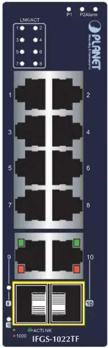
Figure 1: I FGS-1022TF Front View
3.2 LED Definition
System
| LED Color Function | ||
| P1 Green | Lights to indicate power input 1 has power. | |
| P2 Green | Lights to indicate power input 2 has power. | |
| Alarm | Red | Lights: indicates either power 1 or power 2 has no power. |
■ Per 10/100BASE-TX Port
| LED Color Function | ||
| LNK/ACT | Green | Lights to indicate that the port is operating at 10/100Mbps. |
| Blinking to indicate that the switch is actively sending or receiving data over that port. | ||
| Off to indicate that the port is linked down. | ||
■ Per Gigabit RJ45 Combo Interface (Port-9\~Port-10)
| LED Color Function | ||
| LNK/ACT | Green | Lights to indicate the link through that port is successfully established. |
| Blinking to indicate that the switch is actively sending or receiving data over that port. | ||
| Off to indicate that the port is linked down. | ||
| 1000 Speed | Amber | Lights to indicate that the port is operating at 1000Mbps. |
| Off to indicate that the port is operating at 10/100Mbps. | ||
■ Per SFP+ Combo Interface (Port 9\~Port 10)
| LED Color Function | ||
| 1000LNK/ACT | Green | Lights to indicate that the port is operating at 1000Mbps. |
| Blinking to indicate that the switch is actively sending or receiving data over that port. | ||
| Off to indicate that the port is linked down. | ||
3.3 Switch Upper Panel
The upper panel of the Industrial Ethernet Switch consists of one terminal block connector within two power input and one relay output.
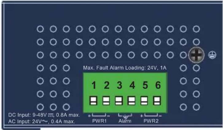
Figure 1: IFGS-1022TF Top View
3.4 Wiring the Power Inputs
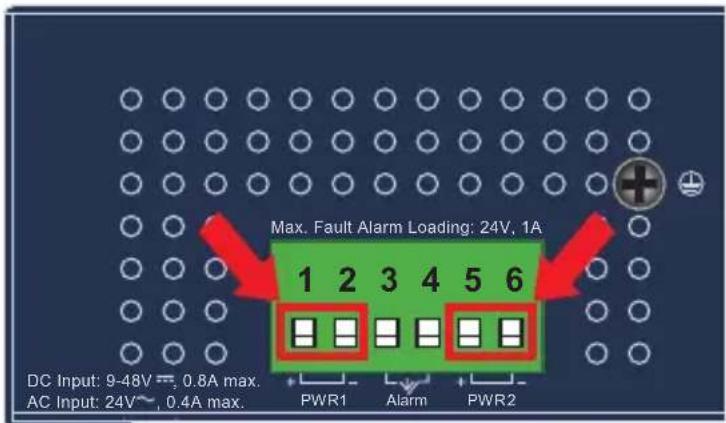
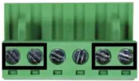
The 6-contact terminal block connector on the top panel of Industrial Ethernet Switch is used for two redundant power inputs. Please follow the steps below to insert the power wire.

When performing any of the procedures like inserting the wires or tightening the wire-clamp screws, make sure the power is OFF to prevent from getting an electric shock.
- Insert positive and negative DC power wires into contacts 1 and 2 for POWER 1, or contacts 5 and 6 for POWER 2.
- Tighten the wire-clamp screws for preventing the wires from loosening.
natural_image
Green circuit board with five circular components, no visible text or symbols1 2 3 4 5 6 Power 1 Alarm Power 2 + - + -

Note
- The wire gauge for the terminal block should be in the range between 12 and 24 AWG.
- The power input range is 9V \~ 48V DC and supports 24V AC.
3.5 Wiring the Fault Alarm Contact
The fault alarm contacts are in the middle of the terminal block connector as the picture shows below. Inserting the wires, the Industrial Ethernet Switch will detect the fault status of the power failure and then forms an open circuit. The following illustration shows an application example for wiring the fault alarm contacts.
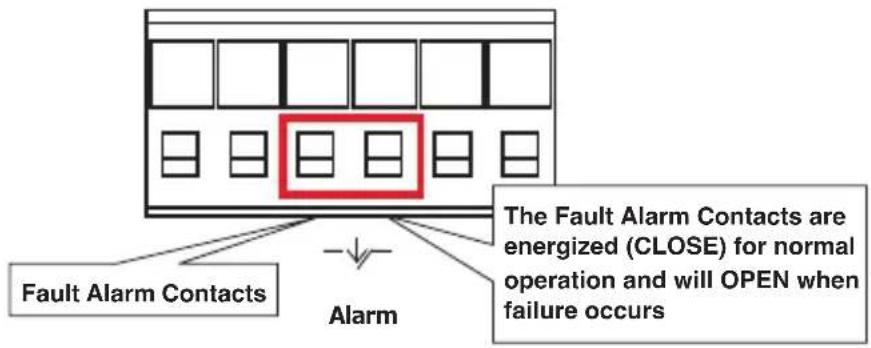
Insert the wires into the fault alarm contacts

Note
-
The wire gauge for the terminal block should be in the range between 12 and 24 AWG.
-
Alarm relay circuit accepts up to 24V DC, 1A.
4. Installation
This section describes the functionalities of the Industrial Ethernet Switch's components and guides you to installing it on the DIN rail and wall. Please read this chapter completely before continuing.

Note
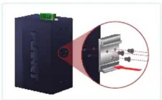
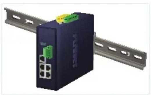
This following pictures show how to install the device. However, the device in the picture is not IFGS-1022TF.
4.1 DIN-rail Mounting Installation
natural_image
Exterior view of a black industrial device with a magnified inset showing internal components (no text or symbols visible)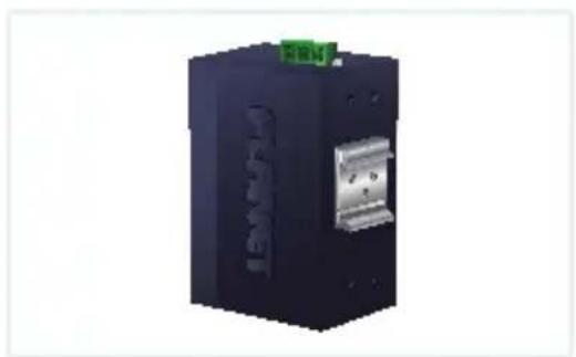
natural_image
3D rendering of a black industrial electronic device with a green connector and metallic housing (no visible text or symbols)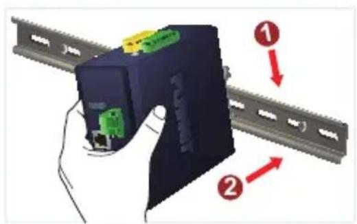
natural_image
3D rendering of a network switch device with ports and connectors, mounted on a metal rack (no visible text or symbols)4.2 Wall-mount Plate Mounting

natural_image
Illustration of a hand using a screwdriver to adjust or install a device (no text or symbols visible)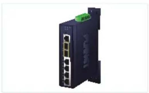
natural_image
Exterior view of a black network switch device with multiple ports and a green logo (no visible text or symbols)4.3 Side Wall-mount Plate Mounting
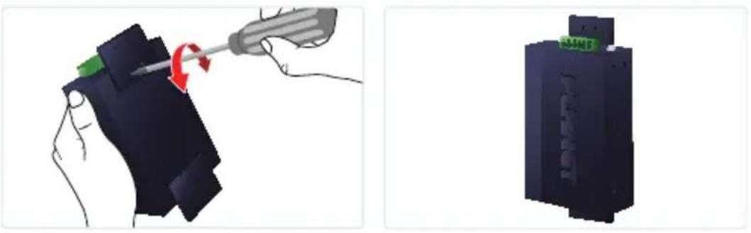
4.4 Grounding the Device
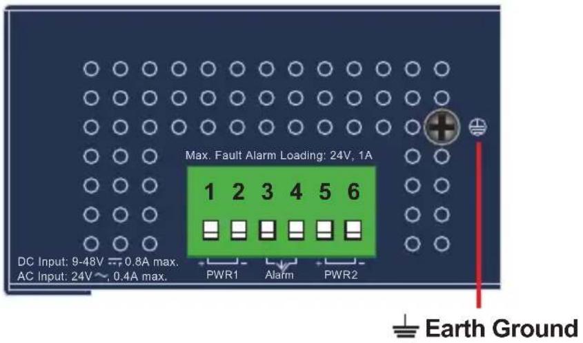
User MUST complete grounding wired with the device; otherwise, a sudden lightning could cause fatal damage to the device. EMD (Lightning) DAMAGE IS NOT CONVERED UNDER WARRANTY.
Customer Support
Thank you for purchasing PLANET products. You can browse our online FAQ resource on PLANET web site first to check if it could solve your need more support information, please contact PLANET switch support team.
PLANET online FAQs:
http://www.planet.com.tw/en/support/faq
Switch support team mail address:
This equipment has been tested and found to comply with the regulations for a Class A digital device, pursuant to Part 15 of the FCC Rules. These limits are designed to provide reasonable protection against harmful interference when the equipment is operated in a commercial environment. This equipment generates, uses, and can radiate radio frequency energy and, if not installed and used in accordance with this user's guide, may cause harmful interference to radio communications. Operation of this equipment in a residential area is likely to cause harmful interference, in which case the user will be required to correct the interference at his own expense.
CE Mark Warning
This is a Class A product. In a domestic environment, this product may cause radio interference, in which case the user may be required to take adequate measures.
WEEE Warning

To avoid the potential effects on the environment and human as a result of the presence of hazardous substances in electrical and electronic equipment, end users of electrical and electronic equipment should understand the meaning of the crossed-out wheeled bin symbol. Do not dispose of WEEE as unsorted municipal waste and have to collect such WEEE separately.
- Industrial 8-Port 10/100TX +
- 2-Port Gigabit TP/SFP Combo Ethernet Switch
- Table of Contents
- Package Contents
- Product Specifications
- Hardware Introduction
- Switch Front Panel
- Front View
- LED Definition
- System
- ■ Per 10/100BASE-TX Port
- ■ Per Gigabit RJ45 Combo Interface (Port-9\~Port-10)
- ■ Per SFP+ Combo Interface (Port 9\~Port 10)
- Switch Upper Panel
- Wiring the Power Inputs
- Wiring the Fault Alarm Contact
- Installation
- DIN-rail Mounting Installation
- Wall-mount Plate Mounting
- Side Wall-mount Plate Mounting
- Grounding the Device
- Customer Support
- CE Mark Warning
- WEEE Warning
Brand : Planet
Model : IFGS-1022TF
Category : Network switch