CXN1860-140BYC - Air conditioner Daizuki - Free user manual and instructions
Find the device manual for free CXN1860-140BYC Daizuki in PDF.


| Product Type | Unitary Ducted Split Air Conditioner |
| Model | Daizuki CXN1860-140BYC |
| Refrigerant | R410A |
| Power Supply (Wired Controller) | 24V AC, 50/60Hz |
| Power Supply (Unit) | 208-230V AC, 60Hz (estimated from MCA/MOCP) |
| Outdoor Unit Dimensions (H x W x D) | 33.5" x 29.5" x 29.5" (85.1 x 74.9 x 74.9 cm) |
| Indoor Unit Dimensions (H x W x D) | 24.5" x 21.3" x 13.75" (62.2 x 54.1 x 34.9 cm) |
| Indoor Unit Depth with Duct | 48.19" (122.4 cm) overall depth |
| Cooling Mode Temperature Range | 16-30°C (actual set range; controller allows 10-37°C) |
| Heating Mode Temperature Range | 5-32°C (actual set 16-30°C) |
| Modes | Cool, Heat, Auxiliary Heater, Fan Only |
| Fan Speeds | Auto and On (continuous) |
| Wired Controller | Included; 24V control, 7-day programmable timer |
| Timer | 4 periods per day, per day of week |
| Display | Temperature, mode, error codes, lock indicator |
| Error Codes | Supports common error codes (F0, E1, etc.) |
| Safety Features | Lock function, electrical shock protection, system protection |
| Installation Requirements | Level within ±2°, clearance 30" service end, 48" above, 6" one side, 12" others |
| Minimum Circuit Ampacity (MCA) | 30 A |
| Maximum Overcurrent Protection (MOCP) | 45 A |
| Refrigerant Charge | Pre-charged for 25 ft line set; additional charge per foot |
| Required Accessories | Liquid line filter drier (field supplied) |
| Maintenance | Periodic cleaning of filters and coil; check refrigerant charge |
Frequently Asked Questions - CXN1860-140BYC Daizuki
User questions about CXN1860-140BYC Daizuki
0 question about this device. Answer the ones you know or ask your own.
Ask a new question about this device
Download the instructions for your Air conditioner in PDF format for free! Find your manual CXN1860-140BYC - Daizuki and take your electronic device back in hand. On this page are published all the documents necessary for the use of your device. CXN1860-140BYC by Daizuki.
USER MANUAL CXN1860-140BYC Daizuki
natural_image
Abstract composition of overlapping gray squares with no text or symbolsFor R410A Series Unitary Ducted Split AC
Owner's Manual
Air Conditioners
Model
CXN1824-070BY□□
CXN1836-105BY□□
CXN1860-140BY□□
- Thank you for choosing Air Conditioners, please read this owner's manual carefully before operation and retain it for future reference.
Contents
Safety Considerations .... 1
- Installation of the Wired Controller ....2
- Wiring Terminals of the Wired Controller 2
- Main Page .... 3
- Function Setting....3
4.1 "ON/OFF" 3
4.2 "System" 4
4.3 "Fan" 4
4.4 “▼/▲” (Temperature Adjustment)....4
4.5 "SET" (Parameters/Functions View and Setting)......5
4.6 "Enter/Hold" 9
4.7 Lock Function....10
4.8 Error Display....10 - Installation Instructions.... 11
5.1 Physical Dimension ...... 11
5.2 Installation Recommendations ....12
5.3 Installation 13
Safety Considerations
Improper installation, adjustment, alteration, service, maintenance, or use can cause explosion, fire, electrical shock, or other conditions which may cause death, personal injury, or property damage. Consult a qualified installer, service agency, or your distributor or branch for information or assistance. The qualified installer or agency must use factory--authorized kits or accessories when modifying this product. Refer to the individual instructions packaged with the kits or accessories when installing. Follow all safety codes. Wear safety glasses, protective clothing, and work gloves. Use quenching cloth for brazing operations. Have fire extinguisher available. Read these instructions thoroughly and follow all warnings or cautions included in literature and attached to the unit. Consult local building codes and National Electrical Code (NEC) for special requirements. Recognize safety information. This is the safety--alert symbol .When you see this symbol on the unit and in instructions or manuals, be alert to the potential for personal injury. Understand these signal words; DANGER, WARNING, and CAUTION. These words are used with the safety--alert symbol. DANGER identifies the most serious hazards which will result in severe personal injury or death. WARNING signifies hazards which could result in personal injury or death. CAUTION is used to identify unsafe practices which may result in minor personal injury or product and property damage. NOTE is used to highlight suggestions which will result in enhanced installation, reliability, or operation.

WARNING
ELECTRICAL SHOCK HAZARD
Failure to follow this warning could result in personal injury or death.
Before installing, modifying, or servicing system, main electrical disconnect switch must be in the OFF position. There may be more than 1 disconnect switch. Lock out and tag switch with a suitable warning label.
natural_image
Symbol of a trash bin with crossed x- and no text or numbers presentThis product must not be disposed together with the domestic waste. This product has to be disposed at an authorized place for recycling of electrical and electronic appliances.
1. Installation of the Wired Controller
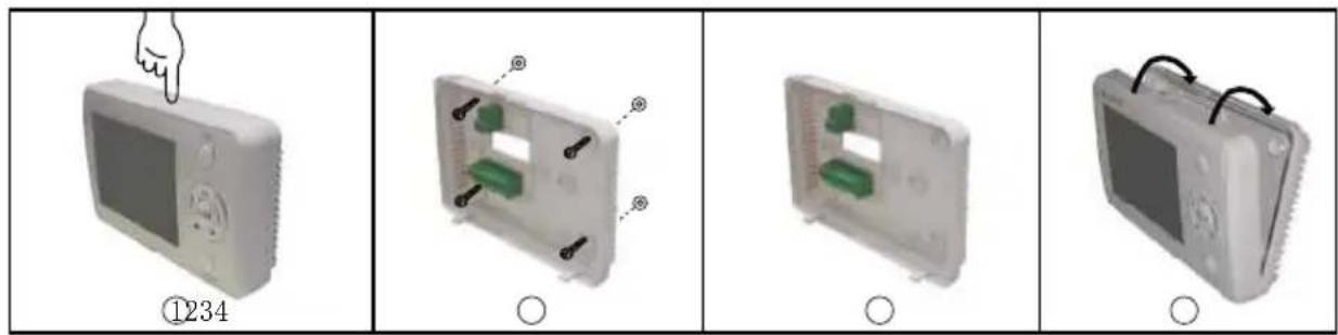
Fig.1 Installation Diagram
Step 1: Press the button at the top of the wired controller to remove the front panel and the bottom plate.
Step 2: Reinstall the bottom plate in accordance with the locating holes either shown in the figure above or decided by the user.
Step 3: Conduct the wiring and see section 2 for more details.
Step 4: Reinstall the front panel.
2. Wiring Terminals of the Wired Controller
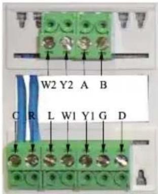
Fig 2 Wiring Terminals Diagram
Table 1
| Terminal Code Description | |
| C 24 Volt (Neutral) | |
| R 24 Volt Emergency (Hot) | |
| O Four-Way Valve | |
| G Indoor Unit | |
| Y1 Compressor 1 | |
| Y2 Compressor 2(Reserved) | |
| W1 Auxiliary Electric Heater 1 | |
| W2 Auxiliary Electric Heater 2 | |
| L Temperature Sensor Error Output | |
| A 485 Communication Port | |
| B 485 Communication Port | |
3. Main Page
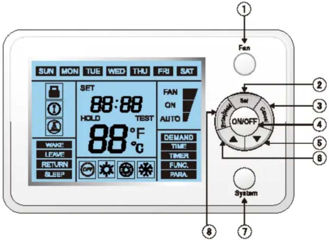
Fig.3 Main Page
① "Fan"
③ "Cancel"
⑤ “▼”
⑦ "System"
② "Set"
④ "ON/OFF"
⑥ “▲”
⑧ "Enter/Hold"
4. Function Setting
4.1 "ON/OFF"
The controller can be turned on/off by pressing this button, with the corresponding ON/OFF symbol displayed.
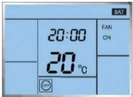
Fig.4
4.2 "System"
One among various mode options can be selected by pressing the "System" button
- As for the cooling only unit, the switchover order of mode options is: E-HEATER→COOL.
- As for the cooling and heating unit, the switchover order of mode options is: HEAT E-HEATER COOL
Note: the unit type is identified by the main board of the unit.
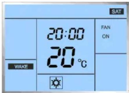
Fig. 5
4.3 "Fan"
It is available to select the desirable fan option by pressing the "Fan" button
- Under the "FAN ON" option, the fan will always keep running.
- Under the "FAN AUTO" option, the fan will be automatically shut down or started up in accordance with the actual Mode and temperature.
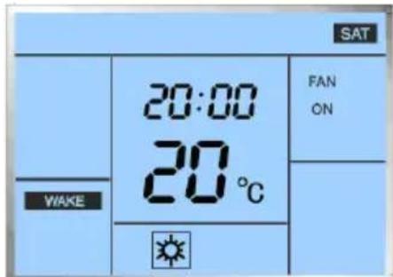
Fig. 6
4.4 “▼/▲” (Temperature Adjustment)
Under the main page, the temperature for the current Mode can be adjusted by pressing the “▼/▲” button.
- During temperature adjustment, the temperature value will blink, with the symbol "SET" displayed.
- After the adjustment, it will automatically back to the main page and display the current environment temperature.
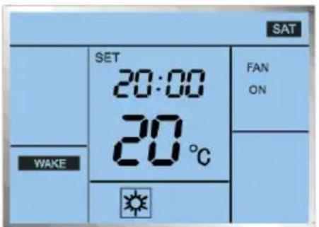
Fig. 7
4.5 "SET" (Parameters/Functions View and Setting)
It is available to go the parameters/functions view and setting page by pressing the "Set" button, and then desired option can be selected by pressing the "▼/▲" button, finally go to the corresponding view and setting page by pressing the "Enter/Hold" button.
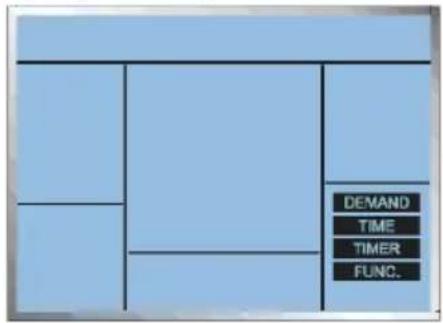
Fig.8 Parameters/Functions View and Setting
4.5.1 "DEMAND"
After accessing to the "DEMAND" page, it is available to select the desired parameter by pressing the "▼/▲" button.
The upper value indicates the desired parameter, while the lower value indicates the parameter No.
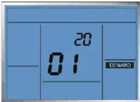
Fig.9
Table 2
| Parameter No. | Parameter Description |
| 01 | Compressor Runtime |
| 02 | Opening Angle of the Electronic Expansion Valve |
| 03 | Outdoor Environment Temperature |
| 04 | Tube Inlet Temperature of the Outdoor Unit |
| 05 | Tube Midway Temperature of the Outdoor Unit |
| 06 Tube Outlet | Temperature of the Outdoor Unit |
| 07 Discharge Air | Temperature of the Outdoor Unit |
| 08 Preset Frequency | |
| 09 Running Frequency | |
| 10 IPM Radiator or IPM Temperature | |
- This page can quit by pressing the "Enter/Hold" button,
- The accumulated "Compressor Runtime" can be cleared by pressing the "System" button for five seconds.
Note: when the accumulated "Compressor Runtime" exceeds 1500 hours, a symbol on the main page will be displayed to remind the user clearing the runtime.
4.5.2 "TIME"
After going into the "TIME" page, it is available to adjust the time.
- Switch to the time value in the order of DAY HOUR MINITE,
- Adjust the blinking value by pressing the “▼/▲” button,
- After the MINUTE is set, press the "Enter/Hold" button for confirmation to make this setting come effective and back to the previous interface.
If the setting is canceled prior to the confirmation, then the related parameter will not be saved and come into effect.
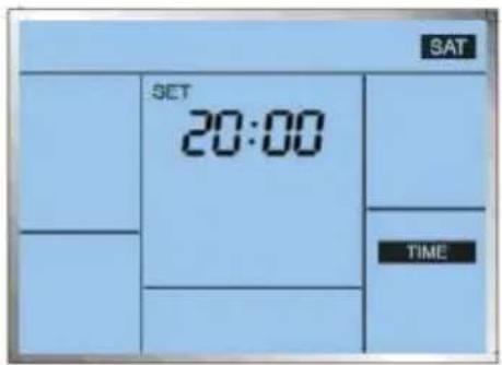
Fig.10
4.5.3 "TIMER"
It is capable of timing four periods for each day of one week,
For instance:
Table 3
| No. Period | Cooling Temperature | Heating Temperature(Auxiliary Heating) |
| Period 1 06:00 24 | °C | 21°C |
| Period 2 08:00 28 | °C | 17°C |
| Period 3 18:00 24 | °C | 21°C |
| Period 4 22:00 26 | °C | 17°C |
When the unit is currently under the cooling mode, the temperature will be set to 24°C automatically at 06:00, 28°C at 8:00, 24°C at 18:00 and 26°C at 22:00.
When the unit is currently under the heating or auxiliary heating mode, the temperature will be set to 21^ C automatically at 06:00, 17^ C at 8:00, 24^ C at 21:00 and 17^ C at 22:00.
① After going to this function page, the day (like, "SAT") will blink and then adjust it through the
“▲ /▼” button.
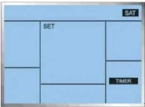
Fig. 11
② After the day is set, press the "Enter/Hold" button to make a confirmation and then go to the "time period" setting status with the time period blinking and then select the desired one through the ▲ or ▼ button.
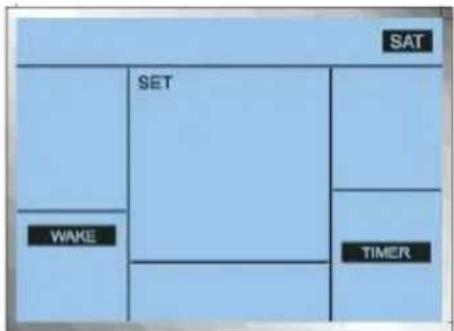
Fig. 12
③ After the time period is selected, press the "Enter/Hold" button to make a confirmation and go the setting status for timing the time period with the "HOUR" blinking and adjust it through the "▲ /▼" button. Sequentially, set the "MINUTE" in the same way.
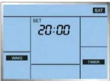
Fig.13
④ After the “MIINUTE” is set, press the “Enter/Hold” button to make a confirmation and go to the setting status for setting the temperature under the cooling mode and adjust it through the ▲ or ▼ button.
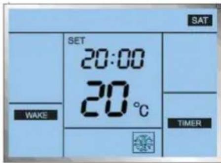
Fig.14
⑤ After the temperature under the cooling mode is set, press the "Enter/Hold" button to make a confirmation and go to the setting status for setting the temperature under the heating mode and adjust it through the ▲ or ▼ button.
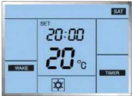
Fig.15
⑥ After that, press the "Enter/Hold" button to make a confirmation and go back to the page shown in step ② and then repeat the steps ②\~⑤ for setting other time periods.
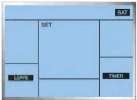
Fig.16
⑦ After the fourth time period is set, then all parameters of these four time periods will be saved and then back to the page for selecting the days of the week. Then, it is available to continue the setting on other days in the same way.
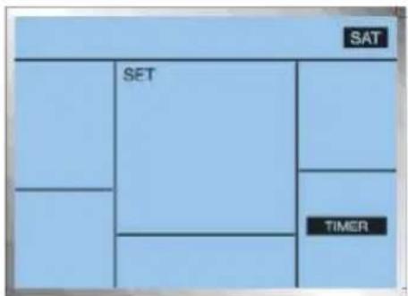
Fig.17
Note: Only when four time periods have been set and the wired controller has backed to the page for selecting the day X, can the timing parameters be memorized together. If the setting quits or the power failure occurs, then the setting of the timing parameters on the day X comes invalid.
4.5.4 "Func."
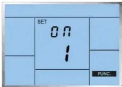
Fig.18
- After going into this page, the function No. blinks and then press the “▼/▲” button to switch the function No.
- Select the desired function No. and next press the 'Enter/Hold" button for confirmation. After that, the value of the selected function No. blinks and adjust it by pressing the "▼/▲" button. Then press the "Enter/Hold" button again to save the setting and back to the previous page.
- This page will be canceled by pressing the "Cancel" button.
Table 4
| No Function Function Code Description | ||
| 01 Memory | ON: The function is activated.OFF: The function is deactivated | |
| 02 Temperature Unit | C:Celsius scaleF: Fahrenheit scale | |
| 03 | Environment Temperature Compensation | -5°C~5°C temperature compensation in accordance with various environment and location. |
| 04 Compressor Time Lag Protection | ON: the function is activatedOFF: the function is deactivated. | |
| 05 Default Reset | ON: the default is resetOFF: the default is not reset | |
4.6 "Enter/Hold"
On the temperature adjustment page, it is available to active the "Hold" function by pressing the 'Enter/Cancel' button, that is, the current setting temperature will be kept unchanged with the change of the setting temperature for each timing period.
This function can be deactivated by pressing the "Enter/Hold" button again.
When this function is activated, the current setting temperature will always be displayed.
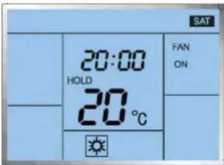
Fig.19
4.7 Lock Function
This function can be activated by simultaneously pressing the “▼/▲” button for five seconds on the main page, and be canceled by another press.
4.8 Error Display
For instance, if the display board ambient temperature sensor error occurs, the error code "F0" and related error symbol will be displayed.
Table 5 Error List
| SN Error Code Error Description | |
| 1 F0 Indoor Ambient Temperature Sensor Error | |
| 2 E1 Compressor High Pressure Protection | |
| 3 E3 Compressor Low Pressure Protection | |
| 4 E4 Compressor Discharge Temperature Protection | |
| 5 E5 Compressor Overload Protection | |
| 6 E8 Over High Tube Temperature Protection of the Outdoor Unit | |
| 7 F2 Outdoor Unit Tube Temperature Sensor Error | |
| 8 F4 Discharge Temperature Sensor Error | |
| 9 e5 Main Board Discharge Temperature Sensor Error | |
| 10 F3 Main Board Ambient Temperature Sensor Error | |
| 11 E6 Communication between the Main Board and the Display Board | |
| 12 EE Main Board Memory Chip Error | |
| 13 c5 Jumper Error | |
| 14 PL DC Bus Under-voltage Protection | |
| 15 PH DC Bus Over-voltage Protection | |
| 16 PA AC Current Protection (Input Side) | |
| 17 H5 IPM Error | |
| 18 Hc PFC Error | |
| 19 Lc Startup Failure | |
| 20 P0 Drive Module Reset Failure | |
| 21 P5 Compressor Over-current | |
| 22 Pc Sensing Circuit Error or Current Sensor Error | |
| 23 H7 Compressor Motor Desynchronization | |
| 24 P6 Communication Error between the Main Board and the Drive | |
| 25 P8 IPM or PFC Over-temperature Protection | |
| 26 P7 IPM or PFC Temperature Sensor Error | |
| 27 ee Drive Memory Chip Error | |
| 28 PU Charging Circuit Error |
Technical Parameters
• Power Supply: 24V AC 50/60HZ
• Maximum Current: 1.5A (Sensing Load)
- Working Environment: Only applicable to indoor environment
- Working temperature: 0^ 50^
- Displayed Environment Temperature: 0^ 37^
When the environment temperature is lower than 0^ C, the displayed value will be “LO”,
When the environment temperature is higher than 37^ C, the displayed value will be "HI".
- The wired controller applied to the inverter unit can set the temperature from 10-37 °C at the COOL mode and 5-32 °C at the HEAT mode. However, 16-30 °C is the real range which can be recognized by the unit, that is, when the temperature is set to be under 16 °C, then 16°C is the real set temperature; or when it is set to be above 30°C, then 30°C is the real set temperature.
5. Installation Instructions
5.1 Physical Dimension
5.1.1 Outdoor Unit
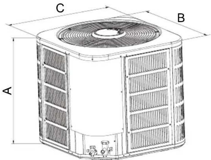
Fig 20 Outdoor Unit Diagram Table 6-Dimension of Outdoor Unit
Unit: Inch
| Model A B C | |||
| CVX1824-070BY | 24-1/2" 24" 24" | ||
| CVX1836-105BY | 29" 28" 28" | ||
| CVX1860-140BY | 33-1/2" 29-1/2" 29-1/2" |
5.1.2 Indoor Unit
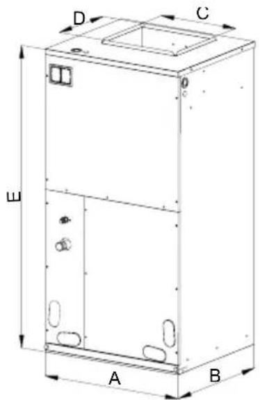
Fig. 21 Indoor Unit Diagram
Table 7-Dimension of Indoor Unit
Unit: Inch
| Model A B C D E | |||||
| CXN1824-070BY | 21" 21-5/16" 10-3/4" 11-5/16" 43-1/2" | ||||
| CXN1836-105BY | 21" 21-5/16" 12-1/4" 11-5/16" 48-3/16" | ||||
| CXN1860-140BY | 24-1/2" 21-5/16" 13-3/4" 11-1/2" 48-3/16" | ||||
5.2 Installation Recommendations
NOTE: In some cases noise in the living area has been traced to gas pulsations from improper installation of equipment.
-
Locate unit away from windows, patios, decks, etc. where unit operation sound may disturb customer.
-
Ensure that vapor and liquid tube diameters are appropriate for unit capacity.
-
Run refrigerant tubes as directly as possible by avoiding unnecessary turns and bends.
-
Leave some slack between structure and unit to absorb vibration.
-
When passing refrigerant tubes through the wall, seal opening with RTV or other pliable silicon--based caulk.(See Fig. 22.)
-
Avoid direct tubing contact with water pipes, duct work, floor joists, wall studs, floors, and walls.
-
Do not suspend refrigerant tubing from joists and studs with a rigid wire or strap which comes in direct contact with tubing. (See Fig. 22.)
-
Ensure that tubing insulation is pliable and completely surrounds vapor tube.
-
When necessary, use hanger straps which are 1 in. wide and conform to shape of tubing insulation. (See Fig. 22.)
-
Isolate hanger straps from insulation by using metal sleeves bent to conform to shape of insulation.
When outdoor unit is connected to factory--approved indoor unit, outdoor unit contains system
refrigerant charge good for 25 ft.
For proper unit operation, check refrigerant charge using charging information located on control box cover and/or in the Check Charge section of this instruction.
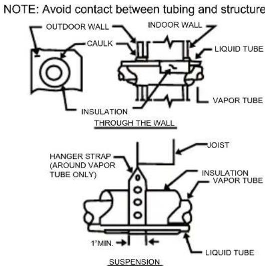
Fig.22 Connecting Tubing Installation
5.3 Installation
5.3.1 Check Equipment & Jobsite
Unpack Unit
Move to final location. Remove carton taking care not to damage unit.
Inspect Equipment
File claim with shipping company prior to installation if shipment is damaged or incomplete. Locate unit rating plate. It contains information needed to properly install unit. Check rating plate to be sure unit matches job specifications.
5.3.2 Install on a Solid, Level Mounting Pad
For hurricane tie downs, contact distributor for details and PE Certification (Professional Engineer), if required. On rooftop applications, mount on level platform or frame. Place unit above a load--bearing wall and isolate unit and tubing set from structure. Arrange supporting members to adequately support unit and minimize transmission of vibration to building. Consult local codes governing rooftop applications.
NOTE: Unit must be level to within ±2° (±3/8 in./ft.) per compressor manufacturer specifications.
5.3.3 Clearance Requirements
When installing, allow sufficient space for airflow clearance, wiring, refrigerant piping, and service. Allow 30 inch clearance to service end of unit and 48 inch above unit. For proper airflow, a 6 inch clearance on 1 side of unit and 12 inch on all remaining sides must be maintained. Maintain a distance of 24 inch between units. Position so water, snow, or ice from roof or eaves cannot fall directly on unit. On rooftop applications, locate unit at least 6 inch above roof surface.
5.3.4 Operating Ambient
The minimum outdoor operating ambient in cooling mode is 67^ F, and the maximum outdoor operating ambient in cooling mode is 115^ F.
5.3.5 Elevate Unit

CAUTION
Failure to follow this caution may result in equipment damage or improper operation.
Unit must be kept free of an accumulation of water and/or ice in the basepan.
Elevate unit per local climate and code requirements to provide clearance above estimated snowfall level and ensure adequate drainage of unit. If using accessory support feet, use installation instructions from kit for installation.
5.3.6 Make Piping Connections

WARNING
PERSONAL INJURY AND UNIT DAMAGE HAZARD
Failure to follow this warning could result in personal injury or death.
Relieve pressure and recover all refrigerant before system repair or final unit disposal.
Use all service ports and open all flow-control devices, including solenoid valves.

CAUTION
UNIT DAMAGE HAZARD
Failure to follow this caution may result in equipment damage or improper operation.
If ANY refrigerant tubing is buried, provide a 6 inch vertical rise at service valve.
Refrigerant tubing lengths up to 36 inch may be buried without further special consideration. Do not bury lines longer than 36 inch.

CAUTION
UNIT DAMAGE HAZARD
Failure to follow this caution may result in equipment damage or improper operation.
To prevent damage to unit or service valves, observe the following:
- Use a brazing shield
- Wrap service valves with wet cloth or use a heat sink material.
Outdoor units may be connected to indoor section using accessory tubing package or field-supplied refrigerant grade tubing of correct size and condition. For tubing requirements beyond 80ft., substantial capacity and performance losses can occur. Refer to Table 8 for field tubing diameters. If refrigerant tubes or indoor coil are exposed to atmosphere, they must be evacuated to 500 microns to eliminate contamination and moisture in the system.
Table 8—Refrigerant Connections and Recommended Liquid and Vapor Tube Diameters(In.)
| UNIT SIZE | Liquid Vapor | |||
| Connection Diameter | Tube Diameter | Connection Diameter | Rated Tube Diameter | |
| 24 3/8 3/8 5/8 5/8 | ||||
| 36 3/8 3/8 3/4 3/4 | ||||
| 42 3/8 3/8 7/8 7/8 | ||||
| 48 1/2 1/2 7/8 7/8 | ||||
Outdoor Unit Connected to Factory Approved Indoor Unit
These outdoor units are carefully evaluated and listed with specific indoor coils for proper system performance.
IMPORTANT: Do not apply indoor coils which are not factory approved to these units

CAUTION
UNIT DAMAGE HAZARD
Failure to follow this caution may result in equipment damage or improper operation. Service valves must be wrapped in a heat-sinking material such as a wet cloth.

CAUTION
UNIT DAMAGE HAZARD
Failure to follow this caution may result in equipment damage or improper operation. Installation of filter drier in liquid line is required.
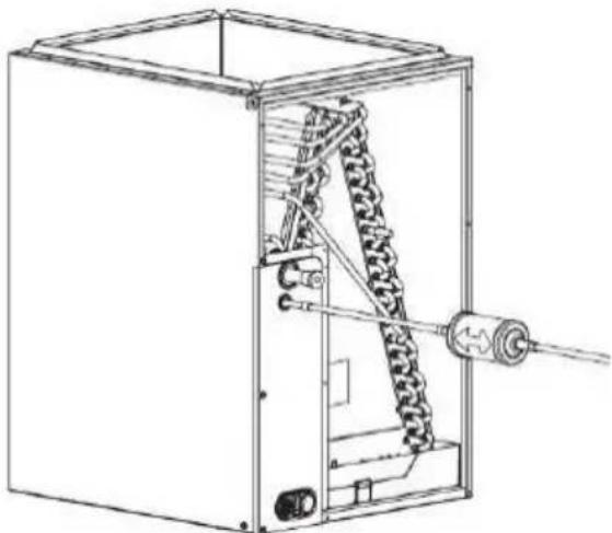
Install Liquid Line Filter Drier Indoor
Refer to Fig. 23 and install filter drier as follows:
- Braze 5 inch liquid tube to the indoor coil.
- Wrap filter drier with damp cloth.
- Braze filter drier to 5 inch long liquid tube from step 1.
- Connect and braze liquid refrigerant tube to the filter drier.
natural_image
Technical line drawing of a mechanical device with internal components and a coiled spring (no text or symbols)Fig.23—Liquid Line Filter Drier
Leak Testing
Leak test all joints indoors, outdoors, and refrigerant tubing.
Evacuate Refrigerant Tubing and Indoor Coil

CAUTION
UNIT DAMAGE HAZARD
Failure to follow this caution may result in equipment damage or improper operation.
Never use the system compressor as a vacuum pump.
Refrigerant tubes and indoor coil should be evacuated using the recommended deep vacuum method of 500 microns. The alternate triple evacuation method may be used if the procedure outlined below is followed.
IMPORTANT: Always break a vacuum with dry nitrogen.
Deep Vacuum Method
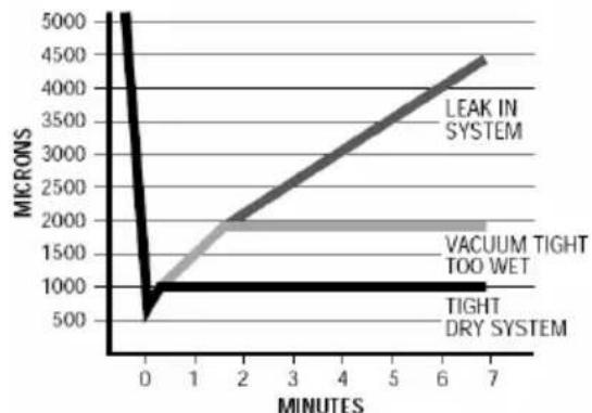
The deep vacuum method requires a vacuum pump capable of pulling a vacuum of 500 microns and a vacuum gage capable of accurately measuring this vacuum depth. The deep vacuum method is the most positive way of assuring a system is free of air and liquid water. See Fig. 24.
line
| MINUTES | LEAK IN SYSTEM | VACUUM TIGHT TOO WET | TIGHT DRY SYSTEM | | -------- | -------------- | -------------------- | ---------------- | | 0 | 5000 | 1000 | 1000 | | 7 | 4500 | 2000 | 1000 |Fig.24- Deep Vacuum Graph
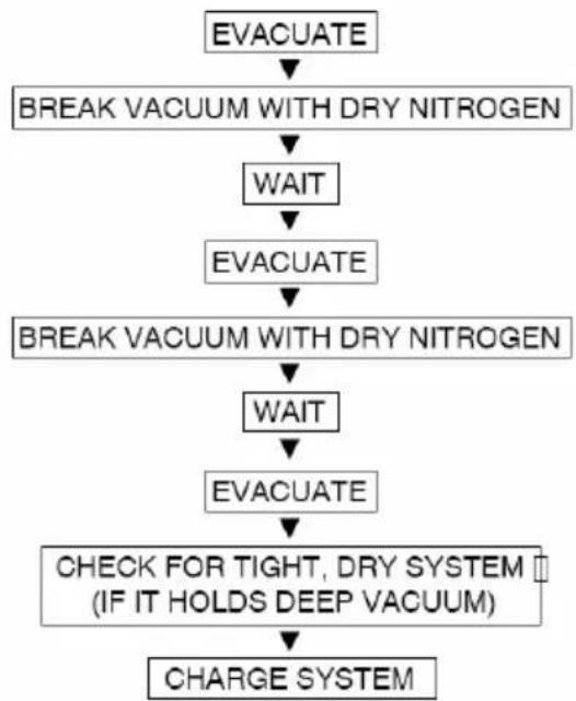
flowchart
graph TD
    A["EVACUATE"] --> B["BREAK VACUUM WITH DRY NITROGEN"]
    B --> C["WAIT"]
    C --> D["EVACUATE"]
    D --> E["BREAK VACUUM WITH DRY NITROGEN"]
    E --> F["WAIT"]
    F --> G["EVACUATE"]
    G --> H["CHECK FOR TIGHT, DRY SYSTEM (IF IT HOLDS DEEP VACUUM)"]
    H --> I["CHARGE SYSTEM"]
Fig.25—Triple Evacuation Method
Triple Evacuation Method
The triple evacuation method should only be used when vacuum pump is only capable of pumping down to 28 inch of mercury vacuum, and system does not contain any liquid water. Refer to Fig. 25 and proceed as follows:
- Pump system down to 28 inch of mercury and allow pump to continue operating for an additional 15 minutes.
- Close service valves and shut off vacuum pump.
- Connect a nitrogen cylinder and regulator to system and open until system pressure is 2 psig.
-
Close service valve and allow system to stand for 1 hour. During this time, dry nitrogen will be able to diffuse throughout the system absorbing moisture.
-
Repeat this procedure as indicated by Fig. 25. System will then be free of any contaminants and water vapor.
Final Tubing Check
IMPORTANT: Check to be certain factory tubing on both indoor and outdoor unit has not shifted during shipment. Ensure tubes are not rubbing against each other or any sheet metal. Pay close attention to feeder tubes, makings sure wire ties on feeder tubes are secure and tight.
Refrigerant Charge Determination and Adjustment
Weight in Charge Method
The unit was pre-charged good for 25 ft application, if the line set longer than 25ft, please refer to the following table for additional charge.
Table 9
| Liquid line size (inch) Additional charge for every additional foot (oz) | |
| 3/8 0.32 | |
| 1/2 0.64 | |
Superheat Method
Table 10
| SYSTEM SUPERHEAT | |||||
| Ambient Condenser Inlet Temp(°F Dry bulb) | Return Air Temperature(°F Dry bulb) | ||||
| 65 70 75 | 80 85 | ||||
| 115 11 | |||||
| 100 11 26 | |||||
| 95 20 18 27 | |||||
| 90 19 24 33 | |||||
| 85 28 29 33 | 34 | ||||
| 80 29 31 33 | 34 | ||||
| 75 29 30 33 | 34 35 | ||||
| 70 29 34 37 | 36 36 | ||||
| 65 32 35 39 | 39 42 | ||||
| 60 34 37 39 | 42 43 | ||||
5.3.7 Make Electrical Connections
NOTE: The signal line of the wired controller must be separated from the power line and the connecting line between the indoor unit and the outdoor unit.

WARNING
ELECTRICAL SHOCK HAZARD
Failure to follow this warning could result in personal injury or death.
Do not supply power to unit with compressor termial box cover removed.
Be sure field wiring complies with local and national fire, safety, and electrical codes, and
voltage to system is within limits shown on unit rating plate. Contact local power company for correction of improper voltage. See unit rating plate for recommended circuit protection device.
NOTE: Operation of unit on improper line voltage constitutes abuse and could affect unit reliability. See unit rating plate. Do not install system where voltage may fluctuate above or below permissible limits.
NOTE: Use copper wire only between disconnect switch and unit.
NOTE: Install branch circuit disconnect of adequate size per NEC to handle unit starting current. Locate disconnect within sight from and readily accessible from unit, per Section 440—14 of NEC.
WARNING: A separate air switch must be furnished for the external power supply of the unit, otherwise it would cause damage to the unit or bodily injury or even death.
Table 11
| Model Number | Minimum Circuit Ampacity-MCA(amps) | Maximum Over Current Protective device-MOCP(amps) | Compressor LRA/RLA | Capability of Air Switch(A) | Minimum Sectional Area Of Earth Wire(mm2 (Outdoor/Indoor) |
| CVX1824-070BY | 15 16.9 -/9 | 7 15 2.1 | |||
| CVX1836-105BY | 24 30.7 -/1 | 3.2 30 3.3 | |||
| CVX1860-140BY | 30 48.8 -/2 | 1.0 45 5.3 |
Route Ground and Power Wires
Remove access panel to gain access to unit wiring. Extend wires from disconnect through power wiring hole provided and into unit control box.

WARNING
ELECTRICAL SHOCK HAZARD
Failure to follow this warning could result in personal injury or death.
The unit cabinet must have an uninterrupted or unbroken ground to minimize personal injury if an electrical fault should occur.
The ground may consist of electrical wire or metal conduit when installed in accordance with existing electrical codes.
Wiring Diagram:
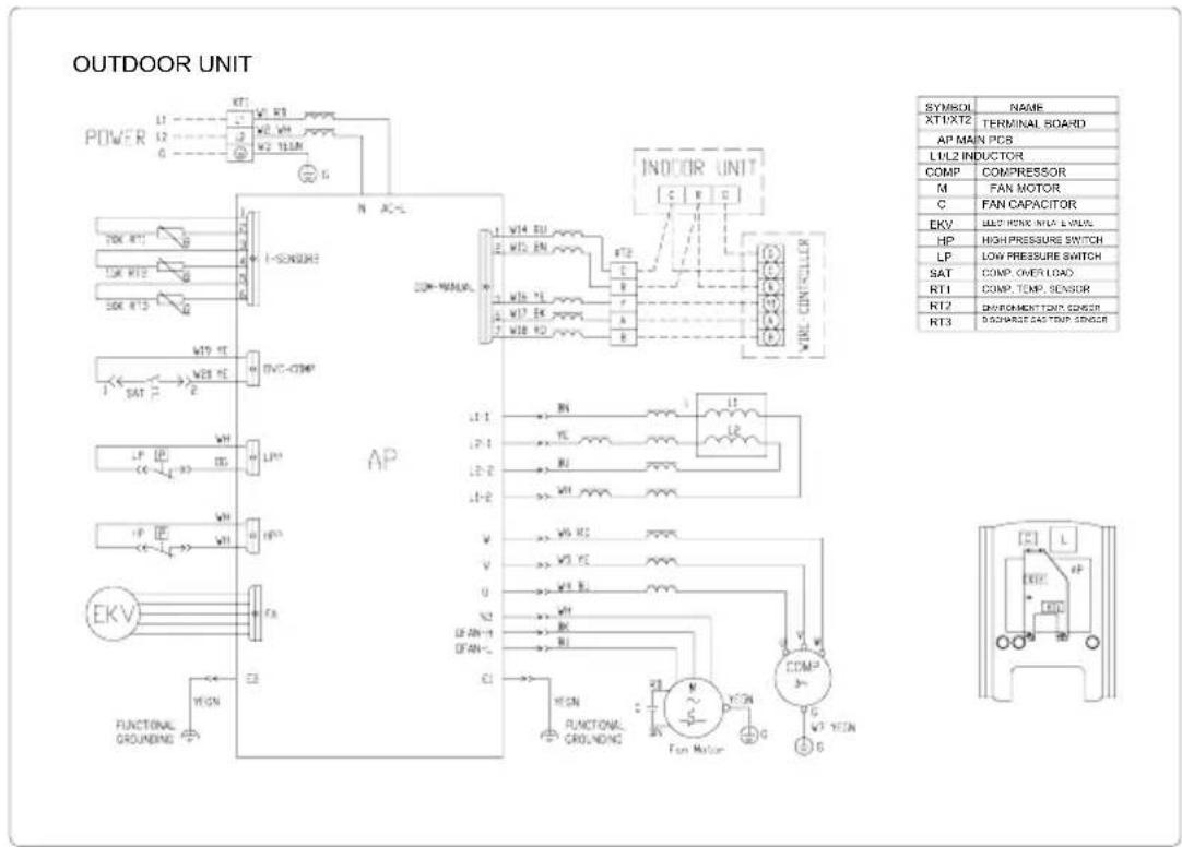
Fig. 26 Electric Wiring of the Outdoor Unit(CVX1824-070BY)
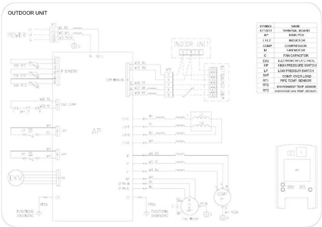
Fig. 27 Electric Wiring of the Outdoor Unit(CVX1836-105BY)

Fig. 28 Electric Wiring of the Outdoor Unit(CVX1860-140BY)
5.3.8 Start-Up

CAUTION
UNIT OPERATION AND SAFETY HAZARD
Failure to follow this caution may result in minor personal injury, equipment damage or improper operation.
To prevent compressor damage or personal injury, observe the following:
- Do not overcharge system with refrigerant.
- Do not operate unit in a vacuum or at negative pressure.
- Do not disable low pressure switch in scroll compressor applications.
● Dome temperatures may be hot.
- In 3 phase applications, incorrect phasing will cause reverse rotation, resulting in elevated noise levels, equalized pressures and reduced current draw. Correct by reversing power connections L1 and L2 on contactor.

CAUTION
PERSONAL INJURY HAZARD
Failure to follow this caution may result in personal injury.
Wear safety glasses, protective clothing, and gloves when handling refrigerant and observe the following:
● Front seating service valves are equipped with Schrader valves.

CAUTION
ENVIRONMENTAL HAZARD
Failure to follow this caution may result in environmental damage.
Federal regulations require that you do not vent refrigerant to the atmosphere. Recover during system repair or final unit disposal.
Follow these steps to properly start up system:
- After system is evacuated, fully open liquid and vapor service valves.
- Unit is shipped with valve stem(s) closed and caps installed. Replace stem caps after system is opened to refrigerant flow (back seated). Replace caps finger—tight and tighten with wrench an additional 1/12 turn.
- Close electrical disconnects to energize system.
- Set room thermostat at desired temperature. Be sure set point is below indoor ambient temperature.
- Set room thermostat to HEAT or COOL and fan control to ON or AUTO mode, as desired.
Operate unit for 15 minutes. Check system refrigerant charge.
5.3.9 Final Checks
IMPORTANT: Before leaving job, be sure to do the following:
- Ensure that all wiring is routed away from tubing and sheet metal edges to prevent rub--through or wire pinching.
Unitary Ducted Split AC - 15. - Ensure that all wiring and tubing is secure in unit before adding panels and covers. Securely fasten all panels and covers.
- Tighten service valve stem caps to 1/12--turn past finger tight.
- Leave Users Manual with owner. Explain system operation and periodic maintenance requirements outlined in manual.
- Fill out Dealer Installation Checklist and place in customer file.
CARE AND MAINTENANCE
For continuing high performance and to minimize possible equipment failure, periodic maintenance must be performed on this equipment. Frequency of maintenance may vary depending upon geographic areas, such as coastal applications.
- For R410A Series Unitary Ducted Split AC
- Contents
- Safety Considerations .... 1
- Safety Considerations
- WARNING
- ELECTRICAL SHOCK HAZARD
- Installation of the Wired Controller
- Wiring Terminals of the Wired Controller
- Main Page
- Function Setting
- "ON/OFF"
- "System"
- "Fan"
- “▼/▲” (Temperature Adjustment)
- "SET" (Parameters/Functions View and Setting)
- "DEMAND"
- "TIME"
- "TIMER"
- "Func."
- "Enter/Hold"
- Lock Function
- Error Display
- Technical Parameters
- Installation Instructions
- Physical Dimension
- Outdoor Unit
- Indoor Unit
- Installation Recommendations
- Installation
- Check Equipment & Jobsite
- Unpack Unit
- Install on a Solid, Level Mounting Pad
- Clearance Requirements
- Operating Ambient
- Elevate Unit
- CAUTION
- Make Piping Connections
- PERSONAL INJURY AND UNIT DAMAGE HAZARD
- UNIT DAMAGE HAZARD
- Outdoor Unit Connected to Factory Approved Indoor Unit
- Install Liquid Line Filter Drier Indoor
- Triple Evacuation Method
- Final Tubing Check
- Refrigerant Charge Determination and Adjustment
- Weight in Charge Method
- Superheat Method
- Make Electrical Connections
- Route Ground and Power Wires
- Wiring Diagram:
- Start-Up
- UNIT OPERATION AND SAFETY HAZARD
- PERSONAL INJURY HAZARD
- ENVIRONMENTAL HAZARD
- Follow these steps to properly start up system:
- Final Checks
- CARE AND MAINTENANCE
Brand : Daizuki
Model : CXN1860-140BYC
Category : Air conditioner