DXAH18E426-21 - Air-conditioner Daizuki - Free user manual and instructions
Find the device manual for free DXAH18E426-21 Daizuki in PDF.

User questions about DXAH18E426-21 Daizuki
0 question about this device. Answer the ones you know or ask your own.
Ask a new question about this device
Download the instructions for your Air-conditioner in PDF format for free! Find your manual DXAH18E426-21 - Daizuki and take your electronic device back in hand. On this page are published all the documents necessary for the use of your device. DXAH18E426-21 by Daizuki.
USER MANUAL DXAH18E426-21 Daizuki
Safety precutions & Installation
DXAH18E426-21
DXAH24E426-20
INSTALLATION MANUAL
SAFETY PRECAUTIONS 02
ACCESSORIES 06
INDOOR UNIT INSTALLATION 07
REFRIGERANT PIPING CONNECTION 17
INSTALLATION OF ELECTRIC AUXILIARY HEAT MODULE (ONLY FOR HEAT FUNCTION MODELS) 21
CONFIRMATION OF INDOOR UNIT 23
OUTDOOR UNIT INSTALLATION 27
WIRING 31
SPECIFICATION 42
AIR EVACUATION 43
NOTE ON ADDING REFRIGERANT 44
TEST RUN 45
Read this manual
Inside you'll find many helpful hints on how to use and maintain your air conditioner properly. Just a little preventive care on your part can save you a great deal of time and money over the life of your air conditioner. These instructions may not cover every possible condition of use, so common sense and attention to safety is required when installing, operating and maintaining this product.
SAFETY PRECAUTIONS
Intended Use
The following safety guidelines are intended to prevent unforeseen risks or damage from unsafe or incorrect operation of the appliance. Please check the packaging and appliance on arrival to make sure everything is intact to ensure safe operation. If you find any damage, please contact the retailer or dealer. Please note modifications or alterations to the appliance are not allowed for your safety. Unintended use may cause hazards and loss of warranty claims.
Explanation of Symbols

WARNING
The signal word indicates a hazard with a medium level of risk which, if not avoided, may result in death or serious injury.

CAUTION
The signal word indicates a hazard with a low degree of risk which, if not avoided, may result in minor or moderate injury.

NOTICE
The signal word indicates important information (e.g. damage to property), but not danger.
Read these operating instructions carefully and attentively before using/commissioning the unit and keep them in the immediate vicinity of the installation site or unit for later use!

WARNING
This appliance is not intended for use by persons (including children) with reduced physical, sensory or mental capabilities, or lack of experience and knowledge, unless they have been given supervision or instruction concerning use of the appliance by a person responsible for their safety. Children should be supervised to ensure that they do not play with the appliance.
⚠️ WARNINGS FOR PRODUCT USE
- If an abnormal situation arises (like a burning smell), immediately turn off the unit and disconnect the power. Call your dealer for instructions to avoid electric shock, fire or injury.
- Do not insert fingers, rods or other objects into the air inlet or outlet. This may cause injury, since the fan may be rotating at high speeds.
- Do not use flammable sprays such as hair spray, lacquer or paint near the unit. This may cause fire or combustion.
- Do not store gasoline or flammable substances near air conditioner. Emitted gas may collect around the unit and cause explosion.
- Do not install your air conditioner in a wet room such as a bathroom or laundry room. Too much exposure to water can cause electrical components to short circuit.
- Do not expose your body directly to cool air for a prolonged period of time.
- Do not allow children to play with the air conditioner. Children must be supervised around the unit at all times.
- If the air conditioner is used together with burners or other heating devices, thoroughly ventilate the room to avoid oxygen deficiency and carbon monoxide build up.
- In certain environments, such as kitchens, server rooms, etc., the use of specially designed air-conditioning units is highly recommended.
- Improper installation, adjustment, alteration, service or maintenance can cause property damage, personal injury or loss of life. Installation and service must be performed by a licensed professional HVAC installer or equivalent, service agency, or the gas supplier.
CAUTION
- Turn off the air conditioner and disconnect the power if you are not going to use it for a long time.
- Make sure that water condensation can drain unhindered from the unit.
- Do not operate the air conditioner with wet hands. This may cause electric shock.
- Do not use device for any other purpose than its intended use.
- Do not climb onto or place objects on top of the outdoor unit.
- Do not allow the air conditioner to operate for long periods of time with doors or windows open, or if the humidity is very high.
• As with any mechanical equipment, contact with sharp sheet metal edges can result in personal injury. Take care while handling this equipment and wear gloves and protective clothing.
ELECTRICAL WARNINGS
- The product must be properly grounded at the time of installation, or electrical shock may occur.
- For all electrical work, follow all local and national wiring standards, regulations, and the Installation Manual. Connect cables tightly, and clamp them securely to prevent external forces from damaging the terminal. Improper electrical connections can overheat and cause fire, and may also cause shock. All electrical connections must be made according to the Electrical Connection Diagram located on the panels of the indoor and outdoor units.
- All wiring must be properly arranged to ensure that the control board cover can close properly. If the control board cover is not closed properly, it can lead to corrosion and cause the connection points on the terminal to heat up, catch fire, or cause electrical shock.
- If connecting power to fixed wiring, an all-pole disconnection device which has at least 3mm clearances in all poles, and have a leakage current that may exceed 10mA, the residual current device(RCD) having a rated residual operating current not exceeding 30mA, and disconnection must be incorporated in the fixed wiring in accordance with the wiring rules.

WARNINGS FOR PRODUCT INSTALLATION
- Installation must be performed by an authorized dealer or specialist. Defective installation can cause water leakage, electrical shock, or fire.
- Installation must be performed according to the installation instructions. Improper installation can cause water leakage, electrical shock, or fire.
(In North America, installation must be performed in accordance with the requirement of NEC and CEC by authorized personnel only.)
- Contact an authorized service provider for repair or maintenance of this unit. This appliance shall be installed in accordance with national wiring regulations.
- Only use the included accessories, parts, and specified parts for installation. Using non-standard parts can cause water leakage, electrical shock, fire, and can cause the unit to fail.
- Install the unit in a firm location that can support the unit's weight. If the chosen location cannot support the unit's weight, or the installation is not done properly, the unit may fall and cause serious injury and damage.
- Install drainage piping according to the instructions in this manual. Improper drainage may cause water damage to your home and property.
- For units that have an auxiliary electric heater, do not install the unit within 1 meter (3 feet) of any combustible materials.
- Do not install the unit in a location that may be exposed to combustible gas leaks. If combustible gas accumulates around the unit, it may cause fire.
- Do not turn on the power until all work has been completed.
- When moving or relocating the air conditioner, consult experienced service technicians for disconnection and reinstallation of the unit.
How to install the appliance to its support, please read the information for details in "indoor unit - installation" and "outdoor unit installation" sections.
- Excessive Weight Hazard - Use two or more people when moving and installing the unit. Failure to do so can result in back or other type of injury.

WARNINGS FOR CLEANING AND MAINTENANCE
- Turn off the device and disconnect the power before cleaning. Failure to do so can cause electrical shock.
- Do not clean the air conditioner with excessive amounts of water.
- Do not clean the air conditioner with combustible cleaning agents. Combustible cleaning agents can cause fire or deformation.

NOTE ABOUT FUSE SPECIFICATIONS
- The air conditioner's circuit board (PCB) may be designed with a fuse to provide overcurrent protection. This fuse must be replaces with identical component.
- The specifications of the fuse, if equipped, are printed on the circuit board, examples of such are T5A/250VAC and T10A/250VAC.

NOTE ABOUT FLUORINATED GASSES (NOT APPLICABLE TO THE UNIT USING R290 REFRIGERANT)
- This air-conditioning unit contains fluorinated greenhouse gasses. For specific information on the type of gas and the amount, please refer to the relevant label on the unit itself or the "Owner's Manual - Product Fiche" in the packaging of the outdoor unit. (European Union products only).
- Installation, service, maintenance and repair of this unit must be performed by a certified technician.
• Product uninstallation and recycling must be performed by a certified technician. - When the unit is checked for leaks, proper record-keeping of all checks is strongly recommended.
The allowed static pressure range of the air conditioner on site is 0-0.80 in-H2O (0-200 Pa). The data below represents the static pressures at full required air flow used for AHRI testing.
| MODEL | 18-24K | 30-36K | 48-60K |
| PRESSURE(Before Jan,1,2023) | 0.10 in-H2O(25Pa) 0.15 in-H2O(37Pa) 0.20 in-H2O(50Pa) | ||
| PRESSURE(After Jan,1,2023) | 0.5 in-H2O(125Pa) 0.5 in-H2O(125Pa) 0.5 in-H2O(125Pa) | ||

NOTE
The maximum functional total external static pressure can not exceed 0.80 in WC or 200 Pa. The airflow reduces significantly beyond 0.80 in WC or 200Pa. System design should allow for the increased resistance of filters as they become dirty.
ACCESSORIES
The air conditioning system comes with the following accessories. Use all of the installation parts and accessories to install the air conditioner. Improper installation may result in water leakage, electrical shock and fire, or equipment failure.
Accessories (Packed with the indoor unit)
| Name | Picture | Quantity |
| Manual |  | 3 |
| Remote controller (optional) |  | 1 |
| Battery (optional) |  | 2 |
| Wired remote controller |  | 1 |
| Cable ties |  | 2 |
| Foam |  | 4 |
| Flare nut (optional) | [6078] | 2 |
| Braze to flare adapter (optional) |  | 2 |
Accessories-optional (Packed with the outdoor unit)
| Name | Picture | Quantity |
| Drain fitting |  | 1 |
| Gasket |  | 1 |

NOTICE
The wired system control functions as an IR receiver for the handheld remote, if the remote is not used it must be retained with the indoor unit to adjust parameters, and for troubleshooting.
INDOOR UNIT INSTALLATION

CAUTION
be sufficient.
The Indoor unit must be electrically grounded per national and local electrical code.
Select the installation location of indoor units

WARNING
DO NOT LOCATIONS:
DO NOT install the indoor unit in a moist environment. Excessive moisture can corrode the equipment, electrical components, and cause electrical shorts.

Areas with strong electromagnetic waves.

Coastal areas with high salt content in the air.

Areas with oil drilling or fracking.

Areas that store flammable materials or gas.
Areas where there may be detergent or other corrosive gases in the air, such as bathrooms, or laundry rooms.
Areas where the air inlet and outlet may be obstructed.

Danger of explosion. Keep flammable materials and vapors, such as gasoline, away from air handler.

WARNING
MUST BE INSTALLED IN A LOCATION
THAT MEETS THE FOLLOWING REQUIREMENTS:
A stable position
√ Securely install the indoor unit on a structure that can support its weight. If the structure is too weak, the unit may fall and cause personal injury, unit and property damage, or death.

√ Enough room for installation and maintenance.
√ Enough room for the connecting pipe and drainpipe.
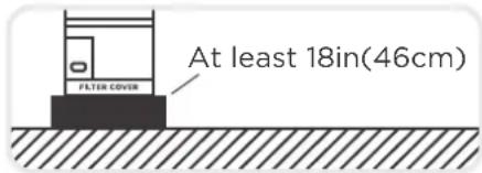
text_image
At least 18in(46cm) FILTER COVER☑ Place air handler so that heating elements are at least 18 inches (46 cm) above the floor for a garage installation. Failure to follow these instructions can result in death, explosion, or fire.
Must support the weight of the indoor unit.

√ The structure that the equipment is suspended from must support the weight of the indoor unit.

WARNING
There must be an airtight seal between the bottom of the air handler and the return air plenum. Use fiberglass sealing strips, foil duct tape, caulking, or equivalent sealing method between the plenum and the air handler cabinet to ensure a tight seal. Return air must not be drawn from a room where this air handler or any gas-fueled appliance (i.e., water heater), or carbon monoxide-producing device (i.e., wood fireplace) is installed.
Preparation and precautions for indoor unit installation
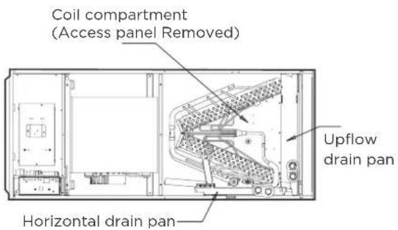
text_image
Coil compartment (Access panel Removed) Upflow drain pan Horizontal drain pan
WARNING
- Please apply sealant around the places where the wires, refrigerant pipes and condensate pipes enter the cabinet.
- Use duct tape or flexible sealant to seal closed anyspace around the holes where the drain lines exit the cabinet. Warm air must not be allowed to enter through any gaps or holes in the cabinet.
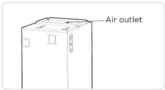
text_image
Air outlet
NOTICE
- Remove all accessories and packing in the air outlet before installation.
Recommended Distances Between the Indoor Unit
The distance between the mounted indoor unit should meet the specifications illustrated in the following diagram.
Horizontal installations
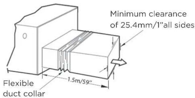
text_image
Minimum clearance of 25.4mm/1" all sides Flexible duct collar 1.5m/59"The outlet side pipe length 1.5m/59".
Vertical installations

text_image
or HOTTER GROUND
text_image
BASO-BEEM 100mm 25mm 30mm 40mm 50mmFixing instructions: When installed vertically (upward or downward), the lower end of the air outlet needs to be connected to the L-shaped metal air duct and fastened by screws.
Indoor unit parts installation size

text_image
C B A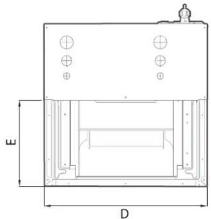
natural_image
Technical line drawing of a mechanical housing or enclosure with dimension labels D and E (no text or symbols present)(unit: mm/inch)
Model A Model B
| Dimensions\Model(Btu/h) | 12K-24K | 30K-48K | 60K 60K | |
| Length of A | mm | 1143 | 1245 | 1346 |
| inch | 45 | 49 | 53 | |
| Length of B | mm | 533 | 533 | 533 |
| inch | 21 | 21 | 21 | |
| Length of C | mm | 445 | 534 | 622 |
| inch | 17-1/2 | 21-1/50 | 24-1/2 | |
| Length of D | mm | 400 | 490 | 580 |
| inch | 15-3/4 | 19-5/16 | 22-27/32 | |
| Length of E | mm | 260 | 260 | 260 |
| inch | 10-1/4 | 10-1/4 | 10-1/4 | |
| Dimensions\Model(Btu/h) | ||
| Length of A | mm | 1245 |
| inch | 49 | |
| Length of B | mm | 533 |
| inch | 21 | |
| Length of C | mm | 534 |
| inch | 21-1/50 | |
| Length of D | mm | 490 |
| inch | 19-5/16 | |
| Length of E | mm | 260 |
| inch | 10-1/4 | |
Recommended size of filter

text_image
t W D(unit: mm/inch)
| Model(Btu/h) 18K-24K 30K-48K 60K | ||||
| Length of W | mm | 406.4 | 495.3 | 584.2 |
| inch | 16 | 20 23 | ||
| Length of D | mm | 508 | 508 | 508 |
| inch | 20 | 20 | 20 | |
| Length of t | mm | 25.4 25.4 | 25.4 | |
| inch | 1 | 1 | 1 | |
Installation Position Requirements

text_image
24inch(min)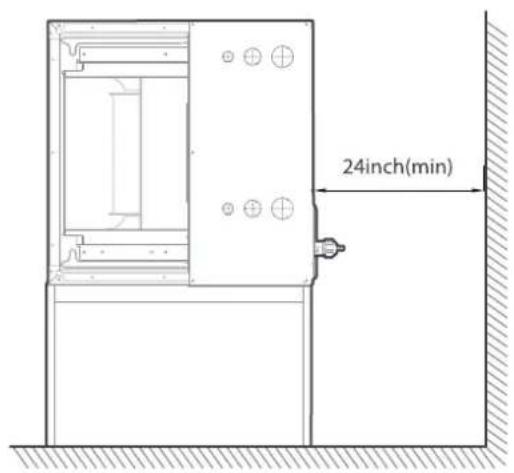
text_image
24inch(min)Horizontal installationsVertical installa

It should be assembled accordance to the instructions.
It should be insulated and use a Vapor Barrier.

It should be Flexible suspension mounted and not fastened

It should be fabricated and installed in accordance with local and/or national codes.
More Requirements
- Air supply and return may be handled in one of several ways best suited to the installation (See table for dimensions for duct inlet and outlet connections). The vast majority of problems encountered with combination cooling systems can be linked to improperly designed or installed duct systems. It is therefore highly important to the success of an installation that the duct system be properly designed and installed. Use flexible duct collars to minimize the transmission of vibration/noise into the conditioned space. Where return air duct is short, or where sound could potentially to be a problem, sound absorbing liner should be used inside the duct.
- Duct must be insulated where it runs through an unconditioned space during the cooling season. The use of a vapor barrier is recommended to prevent absorption of moisture from the surrounding air into the insulation.
- The supply air duct connection should be properly sized by use of a transition to match unit opening.
- All ducts should be suspended using flexible hangers and never fastened directly to the structure. This unit is not designed for nonducted (freeblow) applications.
- Duct work should be fabricated and installed in accordance with local and/or national codes.

CAUTION
A field-fabricated secondary drain pan, with a drain pipe to the outside of the building, is required in all installations over a finished living space or in any area that may be damaged by overflow from the main drain pan. In some localities, local codes may require a secondary drain pan for any horizontal installation.
Selection of installation direction
Different installation directions
The units can be installed in a vertical (down and up) and Horizontal(right and left) configuration.

natural_image
Line drawing of a refrigerator with front panel and side door (no text or symbols)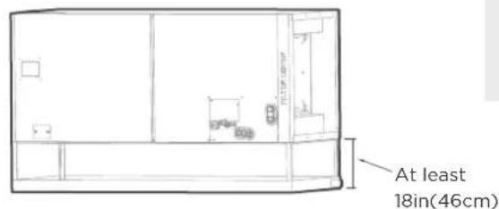
text_image
At least 18in(46cm)HorizontalVertical up

NOTICE
Airflow direction of different installation directions

natural_image
Technical line drawing of a mechanical assembly with top and side views (no text or symbols)
Upflow Downflow

natural_image
Technical line drawing of a mechanical assembly with internal components and mounting holes (no text or symbols)

natural_image
Technical line drawing of a mechanical assembly with directional arrows indicating movement (no text or symbols)Horizontal left

natural_image
Technical line drawing of an electronic device interior with directional arrows indicating flow or movement (no text or symbols present)Horizontal right

NOTICE
Vertical up and horizontal left installation does not need to change the direction of evaporator.
Connecting the wire and pipes(pipes and drainage pipes)
Please follow these steps to perform Vertical down installation and Horizontal right installation:

natural_image
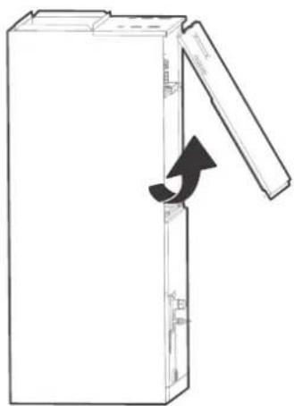
Line drawing of an open refrigerator with a door open, showing internal components and a circular component inside (no text or symbols)Step 1
Open the upper cover.
Step 2
Open the cover of the electronic control box.
Step 3
Connect the wire according to the wiring diagram.
Step 4
Connect the pipes and install the drainage pipes.
Down flow and horizontal right instructions

NOTICE
The unit may be installed in one of the upflow, downflow, horizontal left or horizontal right orientations.
text_image
回路盒 GY/端Step 1
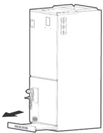
Remove the filter door, then take the filter off.
natural_image
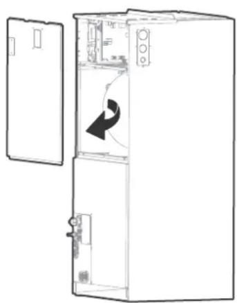
Line drawing of an open industrial refrigerator with a black arrow indicating a component (no text or symbols present)Step 2
Remove the upper cover assembly.
text_image
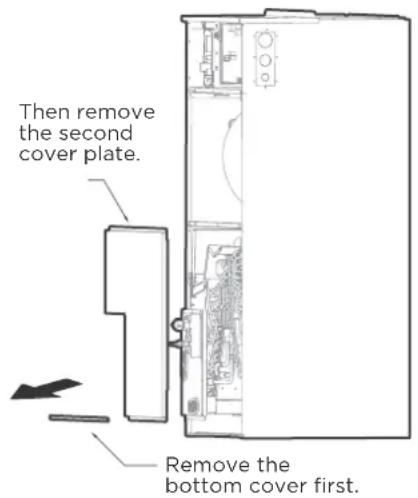
Then remove the second cover plate. Remove the bottom cover first.Step 3
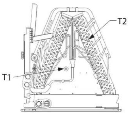
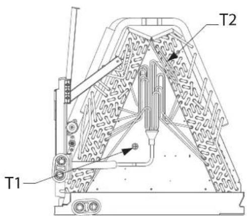
Remove evaporator cover plate.
Step 4
Indication of the position of each temperature temperature sensor of the evaporator, confirm your model.
18-24K model

text_image
T1 T230-48K model
text_image
T1 T260K model
text_image
T1 T2Step 5
Unplug temperature sensors T1,T2 from the control board.
T1: Room temperature sensor
T2: Evaporator central sensor plug

text_image
Technical diagram of a server rack with labeled components T1 and T2, showing internal layout and component details.
NOTICE
T1 is only available for some models.
Step 6
Remove T1,T2 sensor wire ties.
natural_image
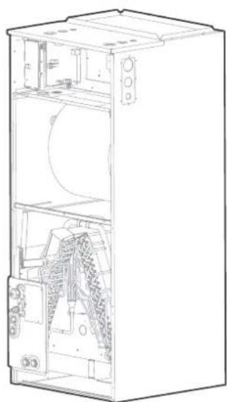
Technical line drawing of an open industrial refrigerator with internal components (no text or symbols)Step 6
Take out the evaporator and drain pan and rotate 180° (when your equipment need to be vertical downed configuration).

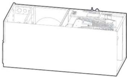
natural_image
Technical line drawing of an open industrial machine with internal components and a directional arrow indicating motion (no text or symbols present)Step 7
Adjust the mounting parts position according to the direction of equipment.

text_image
Technical diagram showing two views of a device with labeled components and directional arrows indicating assembly or operation.Step 8
Reinstall the evaporator and drain pan.

natural_image
Technical line drawing of an open refrigerator with internal compartments and a door, showing no text or symbols.Step 9
Reinstall T1, T2 sensor plug and tie up the sensor wires.

flowchart
graph TD
    A["Cut the foam gasket"] --> B["Remove knockouts as shown in the figure."]
    B --> C["Hook the wire into the buckle and go down from the wire slot."]
    C --> D["Replace foam gasket over wires."]

NOTICE
The wire body needs to pass through the wire groove from the drain pan and be stuck on the hook of the drain pan.
Step 10
The evaporator is assembled in place.
natural_image
Line drawing of an open rectangular electronic device with internal components (no text or symbols)Step 11
Use cable ties to fix the room temperature sensor as shown in the figure.
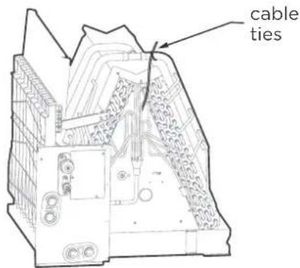
text_image
cable tiesStep 12
Reinstall evaporator cover plate.
natural_image
Line drawing of a multi-tiered refrigerator with doors, wheels, and ventilation slots (no text or labels)Step 13
Connect the wire according to the wiring diagram.
Step 14
Reassemble the upper cover and Reinstall the filter, filter cover plate.

natural_image
Line drawing of an open refrigerator with door, ventilation slots, and a scroll wheel (no text or symbols)Step 15
Connect the pipes and install the drainage pipes.

CAUTION FOR ALL PIPES INSTALLATION
• Insulate all piping to prevent condensation, which could lead to water damage.
- The drainpipe is used to drain water away from the unit. If the drainpipe is bent or installed incorrectly, water may leak and cause a water-level switch malfunction.
- In HEAT mode, the outdoor unit will discharge water. Ensure that the drain hose is placed in an appropriate area to avoid water damage and icy conditions on walkways.
- DO NOT pull the drainpipe forcefully. This could disconnect it.

NOTICE
If installed above a finished living space, a secondary drain pan (as required by many building codes), must be installed under the entire unit and its condensate drain line must be routed to a location such that the user will see the condensate discharge.

NOTICE ON PURCHASING PIPES
Installation requires pvc pipe or other suitable material per local and national codes, which can be obtained at your local hardware store or dealer.

WARNING
- After removal of drain pan plug(s), check drain hole(s) to verify that drain opening is fully open and free of any debris. Also check to make sure that no debris has fallen into the drain pan during installation that may plug up the drain opening. Seal around the exiting drain pipe, liquid and suction lines to prevent infiltration of humid air.
- On units of this type, where the blower “draws” rather than “blows” air through the coil, traps must be installed in the condensate drain lines (primary and auxiliary, if used). Traps prevent the blower from drawing air through the drain lines into the air supply.
Vertical Installations
These units operate with a negative pressure at the drain connections and a drain trap is required. The trap needs to be installed as close to the unit as possible. Make sure the top of the trap is below the connection to the drain pan to allow complete drainage of the pan.
Vertical discharge

text_image
Primary drain Main drain hole Overflow drain hole FILTER COVER
text_image
>50mm(2") Anti-syphon air vent >50mm(2") Vent T Lean over 1/50 Drain Trap >50mm(2") >50mm(2")
NOTICE
Horizontal runs must also have an anti-siphon air vent(standpipe) install ahead of the horizontal run to eliminate air trapping.
NOTE ON DRAINPIPE INSTALLATION
- The Figure shows how to trap or plug all drains during vertical discharge.
- The Figure shows how to trap or plug all drains during right-hand discharge.
- The seal plug are supplied as accessories and should be screwed tightly only by hand.
- Incorrect installation could cause water to flow back into the unit and flood

CAUTION
The drainpipe outlet should be at least 5cm(1.9in) above the ground. If it touches the ground, the unit may become blocked and malfunction.
REFRIGERANT PIPING CONNECTION
WARNING
All field piping must be completed by a licensed technician and must comply with the local and national regulations.
- When the air conditioner is installed in a small room, measures must be taken to prevent the refrigerant concentration in the room from exceeding the safety limit in the event of refrigerant leakage. If the refrigerant leaks and its concentration exceeds its proper limit, hazards due to lack of oxygen may result.
- When installing the refrigeration system, ensure that air, dust, moisture or foreign substances do not enter the refrigerant circuit. Contamination in the system may cause poor operating capacity, high pressure in the refrigeration cycle, explosion or injury.
- Ventilate the area immediately if there is refrigerant leakage during the installation. Leaked refrigerant gas is both toxic and may be flammable. Ensure there is no refrigerant leakage after completing the installation work
Notes on pipe length and elevation
The maximum length and drop height based on models.(Unit:m/ft.)
| Capacity (Btu/h) | MaxLength of piping | Maximum drop height | ||
| ft. | m | ft. | m | |
| 18k | 98.4 | 30 | 65.6 | 20 |
| 24k/30k | 164 | 50 | 82 | 25 |
| 36k/48k/60k | 213 | 65 | 98.4 | 30 |
Ensure that the length of the refrigerant pipe, the number of bends, and the drop height between the indoor and outdoor units meets the requirements
| Name Shape | Quantity(PC) | ||
| Connecting pipe assembly | Liquid side | 6.35(1/4in) | Parts you must purchase separately.Consult the dealer about the proper pipe size of the unit you purchased. |
| 9.52(3/8in) | |||
| Gas side | 12.7(1/2in) | ||
| 16(5/8in) | |||
| 19(3/4in) | |||
| 22(7/8in) | |||
CAUTION
Oil traps
If oil flows back into the outdoor unit's compressor, this might cause liquid compression or deterioration of oil return. Oil traps in the rising gas piping can prevent this.
An oil trap should be installed every 6m(20ft) of vertical suction line riser
installed every 10m(32.8ft) of vertical
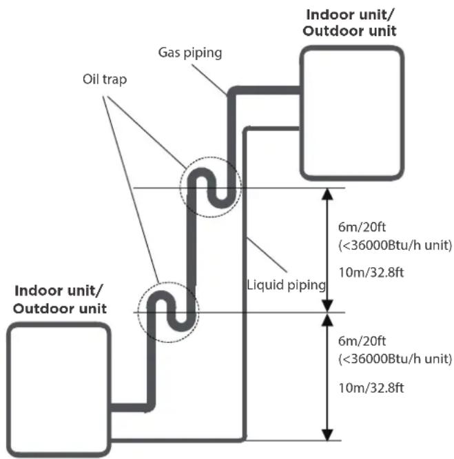
text_image
Oil trap Gas piping Indoor unit/ Outdoor unit 6m/20ft (<36000Btu/h unit) 10m/32.8ft Liquid piping 6m/20ft (<36000Btu/h unit) 10m/32.8ft Indoor unit/ Outdoor unitConnection Instructions—Refrigerant Piping
Step 1: Cut pipes
When preparing refrigerant pipes, take extra care to cut and flare them properly. This will ensure efficient operation and minimize the need for future maintenance.
Measure the distance between the
• indoor and outdoor units.
Using a pipe cutter, cut the pipe a
- little longer than the measured distance.
Make sure that the pipe is cut at a
• perfect 90° angle.

text_image
90° Oblique Rough Warped
DO NOT DEFORM PIPE WHILE CUTTING
Be extra careful not to damage, kink, or deform the pipe while cutting. This will drastically reduce the heating performance
Step 2: Remove burrs
Burrs can affect the air-tight seal of refrigerant piping connection. They must be completely removed.
- Hold the pipe at a downward angle to prevent burrs from falling into the pipe.
- Using a reamer or deburring tool, remove all burrs from the cut section of the pipe.

text_image
Point down Pipe ReamerStep 3: Flare pipe ends
Proper flaring is essential to achieve an airtight seal.
• After removing burrs from cut pipe, seal the ends with PVC tape to prevent foreign materials from entering the pipe.
• Sheath the pipe with insulating material.
- Place flare nuts on both ends of pipe. Make sure they are facing in the right direction, because you can't put them on or change their direction after flaring.
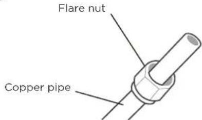
text_image
Flare nut Copper pipe- Remove PVC tape from ends of pipe when ready to perform flaring work.
- Clamp flare from on the end of the pipe. The end of the pipe must extend beyond the flare form.
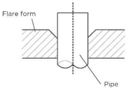
text_image
Flare form Pipe- Place flaring tool onto the form.
- Turn the handle of the flaring tool clockwise until the pipe is fully flared.
PIPING EXTENSION BEYOND FLARE FORM
| Pipe gauge | Tightening torque | Flare dimension(A) (Unit:mm/Inch) | Flare shape | |
| Min. Max. | ||||
| ∅ 6.35 (∅ 1/4") | 18-20 N.m (180-200kgf.cm) | 8.4/0.33 | 8.7/0.34 | 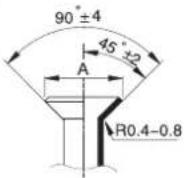 |
| ∅ 9.52 (∅3/8") | 32-39 N.m (320-390kgf.cm) | 13.2/0.52 | 13.5/0.53 | |
| ∅ 12.7 (∅ 1/2") | 49-59 N.m (490-590kgf.cm) | 16.2/0.64 | 16.5/0.65 | |
| ∅ 16 (∅ 5/8") | 57-71 N.m (570-710kgf.cm) | 19.2/0.76 | 19.7/0.78 | |
| ∅ 19 (∅ 3/4") | 67-101 N.m (670-1010kgf.cm) | 23.2/0.91 | 23.7/0.93 | |
| ∅ 22 (∅ 7/8") | 85-110 N.m (850-1100kgf.cm) | 26.4/1.04 | 26.9/1.06 | |
- Remove the flaring tool and flare form, then inspect the end of the pipe for cracks and even flaring.
Step 4: Connect pipes
Connect the copper pipes to the indoor unit first, then connect it to the outdoor unit. You should first connect the low-pressure pipe, then the highpressure pipe.
- When connecting the flare nuts, apply a thin coat of refrigeration oil to the flared ends of the pipes.
- Align the center of the two pipes that you will connect.
- Tighten the flare nut snugly by hand.
• Using a wrench, grip the nut on the unit tubing. - While firmly gripping the nut, use a torque wrench to tighten the flare nut according to the torque values in above table.

NOTICE
Use both a spanner and a torque wrench when connecting or disconnecting pipes to/from the unit.

text_image
Torque wrench
CAUTION
Ensure to wrap insulation around the piping. Direct contact with the bare piping may result in burns or frostbite.
- Make sure the pipe is properly connected. Over tightening may damage the bell mouth and under tightening may lead to leakage.

NOTICE
MINIMUM BEND RADIUS
Carefully bend the tubing in the middle according to the diagram below.
DO NOT bend the tubing more than 90° or more than 3 times.
Use appropriate tool
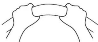
natural_image
Simple line drawing of two hands holding a scroll (no text or symbols)min-radius 10cm(3.9)
• After connecting the copper pipes to the indoor unit, wrap the power cable, signal cable and the piping together with binding tape.

NOTICE
DO NOT intertwine or cross the signal cable with any other wiring.
- Thread this pipeline through the wall and connect it to the outdoor unit.
• Insulate all the piping, including the valves of the outdoor unit. - Open the stop valves of the outdoor unit to start the flow of the refrigerant between the indoor and outdoor unit.
CAUTION
Check to make sure there is no refrigerant leak after completing the installation work. If there is a refrigerant leak, ventilate the area immediately and evacuate the system (refer to the Air Evacuation section of this manual).
Air-Handler Air Conditioners Refrigerant Piping Connection
Correct Refrigerant piping Connecting installation methods
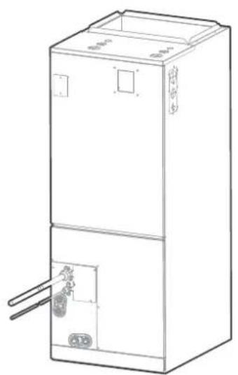
natural_image
Line drawing of a multi-tiered industrial refrigerator with doors and control panel (no text or symbols)Plan 1 P
natural_image
Line drawing of a two-tier industrial electrical cabinet with control panel and buttons (no text or symbols)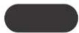
Heating performance
After the unit is installed, wrap the piping and brass fitting with foam tape.
text_image
Foam Tape 回流CO2球INSTALLATION OF ELECTRIC AUXILIARY HEAT MODULE
(ONLY FOR HEAT FUNCTION MODELS)

NOTICE
Installation must be performed by an licensed contractor. Please make necessary precaution when performing the installation operation.
Accessories Preparations for Installation
| Name Name | Quantity | Quantity | |
| Manual | 2 | Silicone breaker cover | 1 |
| Foam gasket | 1 | Electric auxiliary heating wiring diagram | 1 |
| Screws | 7 | Circuit breaker label | 1 |
Model size selection
For installations requiring supplemental heating, the optional Electric Auxiliary Heat Module is available in sizes from 3kW to 25kW to accommodate appropriate sizing given the specific heat load and electrical requirements of each installation. Please refer to the table below for selection of available sizes of each model, being sure to avoid improper matching.
Only use matched modules certified for use with model. Please refer to the Electric Auxiliary Heat Model specification for additional details to ensure proper selection and installation.
Before installation, please confirm the electric auxiliary heat module and supplied accessories are complete and free of any damage. Do not attempt to install if damage is present.
Electric Auxiliary Heat Module installation and Wiring Operation
Step 1
Open the upper cover.
natural_image
Diagram of a door handle with an arrow indicating clockwise motion (no text or symbols)Step 2
Use tools to remove the knock-out holes of upper cover.

natural_image
Simple line drawing of a rectangular object with a small protrusion and an arrow pointing to its top-right corner (no text or symbols)Step 3
Remove the terminal block and power wires, loosen the screws, and remove the electric auxiliary heating cover.
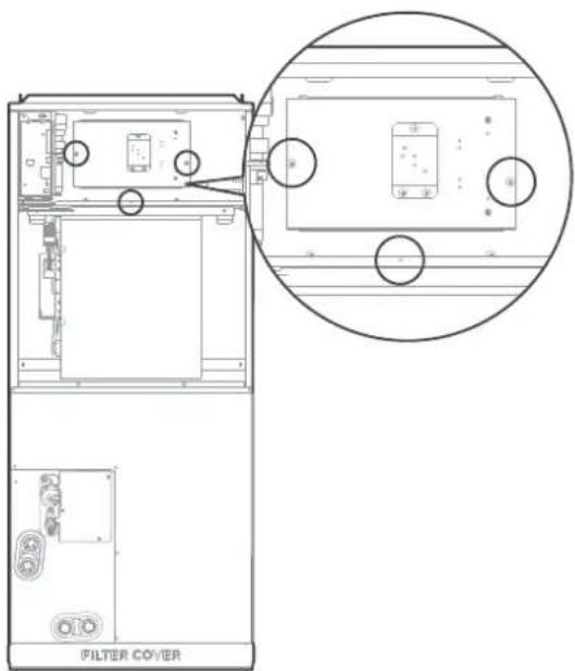
text_image
FILTER COVERStep 4
Install the electric auxiliary heating assembly the front, and note that the support assembly must lock into the support holes in the back of the cabint.
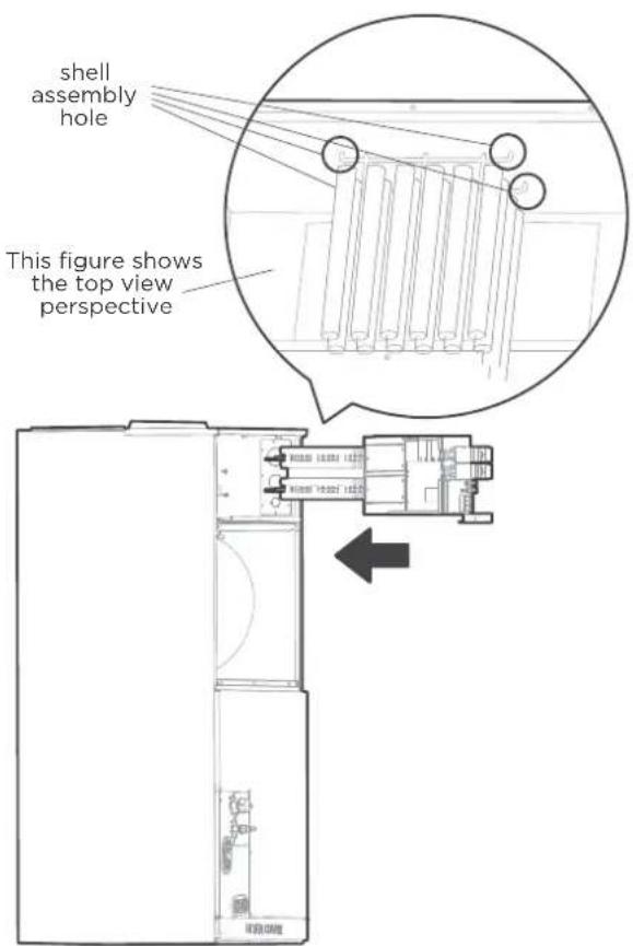
text_image
shell assembly hole This figure shows the top view perspectiveStep 5
Tighten the mounting screws.
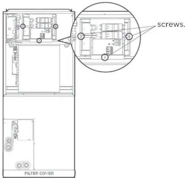
text_image
screws. FILTER COVERStep 6
Wire according to the wiring nameplate. Apply the wiring diagram to the inside cover wiring is completed for future reference and maintenance.
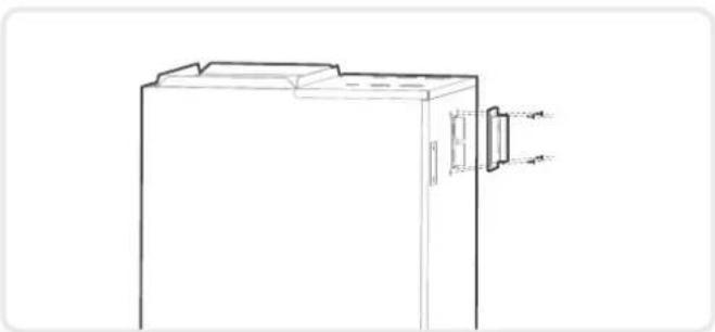
Step 7
Install the upper cover, and the silicone breaker cover.
natural_image
Technical line drawing of a cabinet or enclosure with mounting bracket and door, showing internal structure (no text or symbols)Step 8
After installing the electric auxiliary heat module, apply the circuit breaker label near the silicone breaker cover that was just applied.
CONFIRMATION OF INDOOR UNIT

NOTICE
Electric auxiliary heating wiring diagram packed with the accessories.
If branch circuit wire lenght exceeds 100 ft, consult NEC 210-19a to determine maximum wire length.
Use 2% voltage drop.
After the electric heating wiring is connected, please confirm before power on:
- Check all wiring and ensure secure connection of all wiring.
- Ensure that wire size is properly selected per NEC or local codes.
| Specifications | Number of circuit breakers | Number of relays | Number of power cord groups | Number of power cord grounding screws |
| 3kW | 1 | 1 | 2 | 2 |
| 5kW | 1 | 1 | 2 | 2 |
| 8kW | 1 | 2 | 2 | 2 |
| 10kW | 1 | 2 | 2 | 2 |
| 15kw | 2 | 3 | 3 | 3 |
| 20kW | 2 | 4 | 3 | 3 |
| 25kW | 3 | 5 | 4 | 4 |
Units without electrical heat
| UNIT SIZE | Rated current(A) | MIN CKT AMPSVOITS-PHASE | BRANCH CIRCUIT | ||
| MIN WIRE SIZE AWG* | FUSE/CKT BKR AMPS | ||||
| 18K | 208/230-1 | 2.0 | 2.5 | 14# | 15.0 |
| 24K | 208/230-1 | 3.0 | 4.0 | 14# | 15.0 |
| 30K | 208/230-1 | 3.5 | 4.5 | 14# | 15.0 |
| 36K | 208/230-1 | 4.0 | 5.0 | 14# | 15.0 |
| 48K | 208/230-1 | 6.0 | 7.5 | 14# | 15.0 |
| 60K | 208/230-1 | 7.0 | 9.0 | 14# | 15.0 |
Use copper wire only to connect unit. If other than uncoated (non-plated) 75°C copper wire (solid wire for 10 AWG and smaller, stranded wire for larger than 10 AWG) is used consult applicable tables of the National Electric Code (ANSI/NFPA 70).

NOTICE
The specification may be different between different models, please refer to indoor unit's nameplate.
Auxiliary Heater Electrical Date
| Heater Part No. | Heater KW | Internal Circuit Protection | CIRCUIT 1 208/230V | CIRCUIT 2 | CIRCUIT 2 | ||||||
| Heater Amps | MCA (1) | MOCP (2) | Heater Amps | MCA (1) | MOCP (2) | Heater Amps | MCA (1) | MOCP (2) | |||
| EAH-03B(UL) | 3 | Ckt Bkr | 10.8/12.0 | 14.0/16.0 | 15.0/20.0 | / | / | / | / | / | / |
| EAH-05B(UL) | 5 | Ckt Bkr | 18.0/20.0 | 23.0/27.0 | 25.0/30.0 | / | / | / | / | / | / |
| EAH-08B(UL) | 8 | Ckt Bkr | 28.8/32.0 | 37.0/42.0 | 40.0/45.0 | / | / | / | / | / | / |
| EAH-10B(UL) | 10 | Ckt Bkr | 36.0/40.0 | 46.0/53.0 | 50.0/60.0 | / | / | / | / | / | / |
| EAH-15B(UL) | 15 | Ckt Bkr | 18.0/20.0 | 23.0/27.0 | 25.0/30.0 | 36.0/40.0 | 46.0/53.0 | 50.0/60.0 | / | / | / |
| EAH-20B(UL) | 20 | Ckt Bkr | 36.0/40 | 46.0/53.0 | 50.0/60.0 | 36.0/40.0 | 46.0/53.0 | 50.0/60.0 | / | / | / |
| EAH-25B(UL) | 25 | Ckt Bkr | 18.0/20.0 | 23.0/27.0 | 25.0/30.0 | 36.0/40.0 | 46.0/53.0 | 50.0/60.0 | 36.0/40.0 | 46.0/53.0 | 50.0/60.0 |
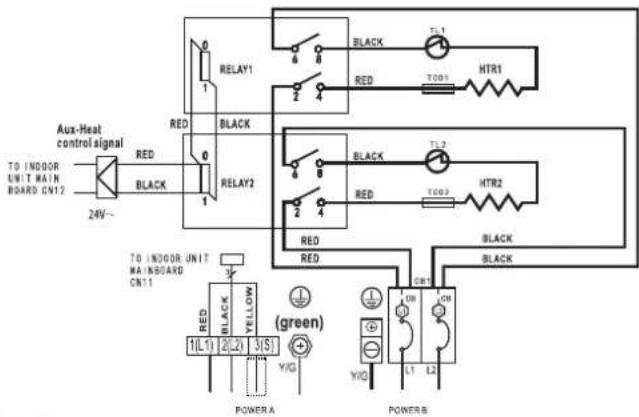
3KW/5KW HEAT KIT
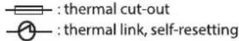
- :thermal cut-out
- :thermal link, self-resetting

text_image
Aux-Heat control signal RED 0 24V~ BLACK RELAY1 6 8 RED TCO1 HTR1 BLACK TL1 TO INDOOR UNIT MAINBOARD cn12 TO INDOOR UNIT MAINBOARD cn11 BLACK RED YELLOW (green) POWER A POWER B 1(L1) 2(L2) 3(S) Y/G Y/G CB1 L1 L2NOTE1:
This symbol indicates the element is optional. The wiring type of the actual unit shall prevail.
NOTE2:
Please attach the nameplate to the cover of the electric control box. All the round holes located on the plate represent numbers. Please refer to the installation Manual for details.
| Round hole number | Relay number | Round hole number | Circuit breaker number |
| RELAY 1 | CB1 | ||
NOTE3: TO BE WIRED IN ACCORDANCE WITH NEC AND LOCAL CODES. NOTE4: POWER A.B.C.D ARE DIFFERENT POWERS.
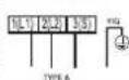
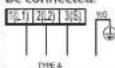
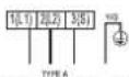
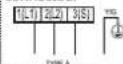
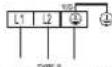
The wiring mode of power supply A shall be based on the type of original wiring terminal of AHU; for type A, S position must be connected to the ourdoor S; for type B, S position shall not be connected.

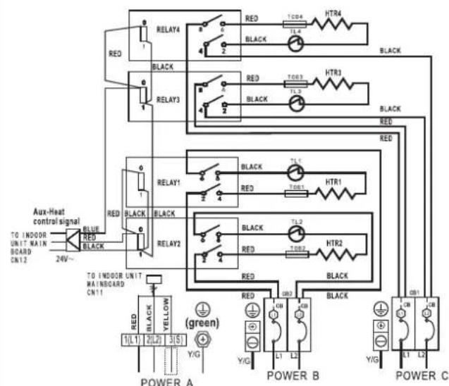
15KW HEAT KIT
- thermal cut-out
- thermal link, self-resetting

text_image
Aux-Heat control signal TO INDOOR UNIT MAIN BOARD CN12 24V~ BLUE BLACK RELAY4 RED T003 HTR3 BLACK TL3 BLACK T001 HTR1 BLACK TL1 BLACK T002 HTR2 BLACK TL2 BLACK T009 BLACK RED RED T002 BLACK TO INDOOR UNIT MAINBOARD CN11 RED BLACK YELLOW (green) L1 L2 3 S1 YIG POWER A POWER B POWER C YIG L1 L2 YIG L1 L2NOTE1:
This symbol indicates the element is optional, The wiring type of the actualunit shall prevail. NOTE2:
Please attach the nameplate to the cover of the electric control box. All the round holes located on the plate represent numbers. Please refer to the installation Manual for details.
| Round hole number | Relay number | Round hole number | Circuit breaker number |
| RELAY 1 | CB1 | ||
| RELAY 2 | CB2 | ||
| RELAY 4 | |||
NOTE3: TO BE WIRED IN ACCORDANCE WITH NEC AND LOCAL CODES. NOTE4: POWER A,B,C,D ARE DIFFERENT POWERS.
The wiring mode of power supply A shall be based on the type of original wiring terminal of AHU; for type A, S position must be connected to the outdoor S; for type B, S position shall not be connected.
8KW/10KW HEAT KIT
- :thermal cut-out
- :thermal link, self-resetting
text_image
Aux-Heat control signal TO INDOOR UNIT MAIN BOARD CN12 24V~ RED BLACK RELAY1 BLACK T1-1 RED TOD1 HTR1 RELAY2 BLACK T1-2 RED TOD2 HTR2 BLACK RED TOD3 BLACK TO INDOOR UNIT MAINBOARD CN11 RED BLACK YELLOW (green) POWER A Y/G Y/G L1 L2 POWER BNOTE1:
This symbol indicates the element is optional. The wiring type of the actual unit shall prevail.
NOTE2:
Please attach the nameplate to the cover of the electric control box. All the round holes located on the plate represent numbers. Please refer to the Installation Manual for details.
| Round hole number | Relay number | Round hole number | Circuit breaker number |
| RELAY 1 | C61 | ||
| × | RELAY 2 | ||
| × × × × × × × × × × × × × × × × × × × × × × × × × × × × × × × × × × × × × × × × × × × × × × × | |||
| × × × × × × × × × × × × × × × × × × × × × × × × × × × × × × × × × × × × × × × × × × × × × × |
NOTE3: TO BE WIRED IN ACCORDANCE WITH NEC AND LOCAL CODES. NOTE4: POWER A B C D ARE DIFFERENT POWERS.
The wiring mode of power supply A shall be based on the type of original wiring terminal of AHU; for type A, S position must be connected to the ourdoor S; for type B, S position shall not be connected.

20KW HEAT KIT
- :thermal cut-out
- :thermal link, self-resetting
text_image
Aux-Heat control signal TO INDOOR UNIT MAIN BOARD CN12 24V~ BLUE RED BLACK RELAY4 BLACK RELAY3 BLACK RELAY1 BLACK RELAY2 BLACK TOD4 HTR4 BLACK TOD3 HTR3 BLACK TOD1 HTR1 TOD2 HTR2 BLACK TLD TLD TLD TLD TLD TLD TLD TLD TLD TLD TLD TLD TLD TLD TLD TLD TLD TLD TLD TLD TLD TLD TLD TLD TLD TLD TLD TLD TLD TLD TLD TLD TLD TLD TLD TLD TLD TLD TLD TLD TLD TMD TLD TMD TLD TMD TLD TMD TLD TMD TLD TMD TLD TMD TLD TMD TLD TMD TLD TMD TLD TMD TLD TMD TLD TMD TLD TMD TLD TMD TLD TMD TLD TMD TLD TMD TLD TMD TLD TMD TLD TMS TLD TMS TLD TMS TLD TMS TLD TMS TLD TMS TLD TMS TLD TMS TLD TMS TLD TMS TLD TMS TLD TMS TLD TMS TLD TMS TLD TMS TLD TMS TLD TMS TLD TMS TLD TMS TLD TMS TLD TMD TLD TMD TLD TMD TLD TMD TLD TMD TLD TMD TLD TMD TLD TMD TLD TMD TLD TMD TLD TMD TLD TMD TLD TMD TLD TMD TLD TMD TLD TMD TLD TMD TLD TMD TLD TMD TLD TMT TLD TMT TLD TMT TLD TMT TLD TMT TLD TMT TLD TMT TLD TMT TLD TMT TLD TMT TLD TMT TLD TMT TLD TMT TLD TMT TLD TMT TLD TMT TLD TMTNOTE1:
This symbol indicates the element is optional, The wiring type of the actual unit shall prevail. NOTE2:
Please attach the nameplate to the cover of the electric control box. All the round holes located on the plate represent numbers. Please refer to the installation Manual for details.
| Round hole number | Relay number | Round hole number | Circuit breaker number |
| RELAY 1 | CB1 | ||
| RELAY 2 | CB2 | ||
| RELAY 3 | |||
| RELAY 4 | |||
NOTE3: TO BE WIRED IN ACCORDANCE WITH NEC AND LOCAL CODES. NOTE4: POWER A,B,C,D ARE DIFFERENT POWERS.
The wiring mode of power supply A shall be based on the type of original wiring terminal of AHU; for type A, S position must be connected to the ourdoor S; for type B, S position shall not be connected.
25KW HEAT KIT

flowchart
graph TD
    A["TO INDOOR UNIT MAINBOARD CN12"] --> B["BLUE RED"]
    A --> C["BLACK RED"]
    D["Aux-Heat control signal 24V~"] --> E["RELAY5"]
    D --> F["RELAY4"]
    D --> G["RELAY3"]
    D --> H["RELAY1"]
    D --> I["BLACK BLACK"]
    J["POWER A"] --> K["RED 1(L1) 2(L2) 3(S)"]
    K --> L["Y/G"]
    M["POWER B"] --> N["RED CB3 L1 L2"]
    N --> O["Y/G"]
    P["POWER C"] --> Q["RED CB2 L1 L2"]
    Q --> R["Y/G"]
    S["POWER D"] --> T["CB1 L1 L2"]
    U["Black"] --> V["RED TC05 TL5 HTR5"]
    V --> W["BLACK"]
    X["Black"] --> Y["RED TC04 TL4 HTR4"]
    Y --> Z["BLACK"]
    AA["Black"] --> AB["RED TC03 TL3 HTR3"]
    AB --> AC["BLACK"]
    AD["Red"] --> AE["RED TC01 HTR1"]
    AE --> AF["BLACK"]
    AG["Red"] --> AH["RED TC02 HTR2"]
    AH --> AI["BLACK"]
    AJ["Red"] --> AK["RED TC01 TL1"]
    AK --> AL["BLACK"]
    AM["Red"] --> AN["RED TC03 TL3"]
    AN --> AO["BLACK"]
NOTE1: □
This symbol indicates the element is optional, The wiring type of the actual unit shall prevail.
NOTE2:
Please attach the nameplate to the cover of the electric control box. All the round holes located on the plate represent numbers. Please refer to the Installation Manual for details.
NOTE3: TO BE WIRED IN ACCORDANCE WITH NEC AND LOCAL CODES.
NOTE4: POWER A,B,C,D ARE DIFFERENT POWERS.
| Round hole number | Relay number | Round hole number | Circuit breaker number |
| ○ | RELAY 1 | ○ | CB1 |
| ○○ | RELAY 2 | ○○ | CB2 |
| ○○○ | RELAY 3 | ○○○ | CB3 |
| ○○○○ | RELAY 4 | ||
| ○○○○○ | RELAY 5 |
The wiring mode of power supply A shall be based on the type of original wiring terminal of AHU; for type A, S position must be connected to the outdoor S; for type B, S position shall not be connected.

OUTDOOR UNIT INSTALLATION
NOTICE
Install the unit by following local switches and regulations, there may be differ slightly between different regions.
Select the installation location of outdoor units
Before installing the outdoor unit, you must choose an appropriate location. The following are standards that will help you choose an appropriate location for the unit.
Proper installation locations meet the following standards:

text_image
60cm(24in) above 30cm(12in) on left 60cm(24in) on right 30cm(12in) from back wall 200cm(79in) in front Front view Top view√ Meets all spatial requirements shown in Installation Space Requirements above.

natural_image
Abstract gear and chain link icon symbol (no text or labels)√ Firm and solid—the location can support the unit and will not vibrate.

natural_image
Gray icon of a person with a megaphone, no text or symbols present√ Noise from the unit will not disturb other people.

text_image
15cm(6in)√ The outdoor unit must be installed on risers of at least 15cm(6in) in height or per local code to get unit above local mean snow fall.

natural_image
Simple line drawing of a window with horizontal lines inside, no text or symbols present√ Good air circulation and ventilation.
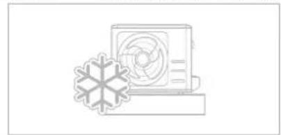
natural_image
Simple line drawing of a refrigerator with a snowflake on the side (no text or symbols)√ Where snowfall is anticipated, take appropriate measures to prevent ice buildup and coil damage.
DO NOT install unit in the following locations:
∅ Near an obstacle that will block air inlets and outlets.
∅ In a location that is exposed to large amounts of dust.
∅ Near animals or plants that will be harmed by hot air discharge.
Near any source of combustible gas
Near a public street, crowded areas, or where noise from the unit will disturb others.
CAUTION:
If the unit is exposed to heavy wind:
Install unit so that air outlet fan is at a 90^ angle to the direction of the wind. If needed, build a barrier in front of the unit to protect it from extremely heavy winds. See Figures below.
If the unit is frequently exposed to heavy rain or snow:
Build a shelter above the unit to protect it from the rain or snow. Be careful not to obstruct air flow around the unit.

text_image
Strong wind Strong wind90^ angle to the direction of the wind
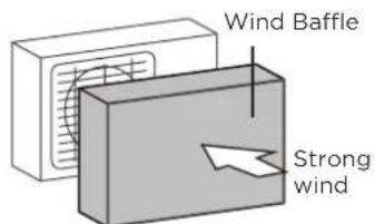
text_image
Wind Baffle Strong windBuild a wind Baffle to protect the unit
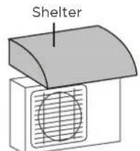
text_image
ShelterBuild a shelter to protect the unit
Install drain fitting(Heat pump unit only)
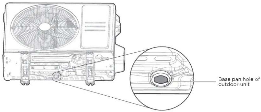
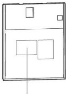
text_image
Base pan hole of outdoor unitFind out the base pan hole of outdoor unit.

text_image
Seal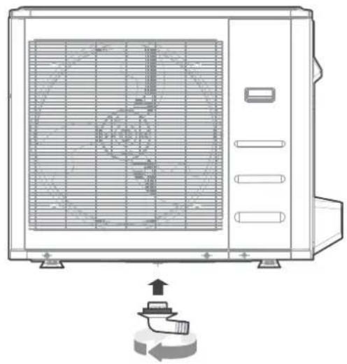
natural_image
Line drawing of a dual-panel air conditioner unit with fan blades and control panel, showing internal airflow direction (no text or symbols)Fit the rubber seal on the end of the drain fitting that will connect to the outdoor unit.
Insert the drain fitting into the hole in the base pan of the unit. The drain fitting will click in place.
Connect a drain hose extension (not included) to the drain fitting to redirect water from the unit during heating mode.

IN COLD CLIMATES
In cold climates, make sure that the drain hose is as vertical as possible to ensure swift water drainage. If water drains too slowly, it can freeze in the hose and flood the unit.
Anchor outdoor unit
The outdoor unit can be anchored to the ground or to a wall-mounted bracket with bolt(M10). Prepare the installation base of the unit according to the dimensions below.
Outdoor Unit Types and Specifications

Front view Top view
| Outdoor Unit Dimensions | Mounting Dimensions | ||||||||
| W | H | D | A B | ||||||
| mm inch | mm inch mm | inch mm | inch mm Inch | ||||||
| 805 | 31-11/16 | 554 | 21-13/16 | 330 | 13 | 511 | 20-1/8 | 317 | 12-1/2 |
| 890 | 35 | 673 | 26-1/2 | 342 | 13-15/32 | 663 | 26-1/8 | 354 | 13-15/16 |
| 946 | 37-1/4 | 810 | 31-29/32 | 410 | 16-5/32 | 673 | 26-1/2 | 403 | 15-7/8 |
| 952 | 37-1/2 | 1333 | 52-1/2 | 415 | 16-11/32 | 634 | 24-35/36 | 404 | 15-29/32 |
(unit: mm/inch)

text_image
25 cm / 9.8" or more 25 cm / 9.8" or more 300 cm / 118" or more 150 cm / 59" or more 60 cm / 23.6" or more 300 cm / 118" or more H L A Rows of The relationRows of series installation
The relations between H, A and L are as follows.
| L | A | |
| 25 cm / 9-13/16in or more | ||
| L > H | Can not be installed | |
If you will install the unit on the ground or on a concrete mounting platform, DO THE FOLLOWING:
Mark the positions for four expansion bolts based on dimensions chart.
Pre-drill holes for expansion bolts.
Place a nut on the end of each expansion bolt.
Hammer expansion bolts into the pre-drilled holes.
Remove the nuts from expansion bolts, and place outdoor unit on bolts.
Put washer on each expansion bolt, then replace the nuts.
Using a wrench, tighten each nut until snug.

WARNING
WHEN DRILLING INTO CONCRETE, EYE PROTECTION IS RECOMMENDED AT ALL TIMES.
If you will install the unit on a wall-mounted bracket, DO THE FOLLOWING:
Mark the position of bracket holes based on dimensions chart.
Pre-drill the holes for the expansion bolts.
Place a washer and nut on the end of each expansion bolt.
Thread expansion bolts through holes in mounting brackets, put mounting brackets in position, and hammer expansion bolts into the wall.
Check that the mounting brackets are level.
Carefully lift unit and place its mounting feet on brackets.
Bolt the unit firmly to the brackets.
If allowed, install the unit with rubber isolator pads o reduce vibrations and noise.

CAUTION
Make sure that the wall is made of solid brick, concrete, or of similarly strong material. The wall must be able to support at least four times the weight of the unit.
WIRING PRECAUTIONS
WARNING
BEFORE PERFORMING ANY ELECTRICAL WORK, READ THESE WARNINGS.
All wiring must comply with local and national electrical codes, regulations and must be installed by a licensed electrician.
All electrical connections must be made according to the Electrical Connection Diagramlocated on the panels of the indoor and outdoor units.
If there is a serious safety issue with the power supply, stop work immediately. Explain your reasoning to the client, and refuse to install the unit until the safety issue is properly resolved.
Power voltage should be within 90-110% of rated voltage. Insufficient power supply can cause malfunction, electrical shock, or fire.
Installation of an external surge suppressor at the outdoor disconnect is recommended.
If connecting power to fixed wiring, a switch or circuit breaker that disconnects all poles and has a contact separation of at least 1/8in (3mm) must be incorporated in the fixed wiring. The qualified technician must use an approved circuit breaker or switch.
Only connect the unit to an individual branch circuit. Do not connect another appliance to that circuit.
Make sure to properly ground the air conditioner.
Every wire must be firmly connected. Loose wiring can cause the terminal to overheat, resulting in product malfunction and possible fire.
Do not let wires touch or rest against refrigerant tubing, the compressor, or any moving parts within the unit.
To avoid getting an electric shock, never touch the electrical components soon after the power supply has been turned off. After turning off the power, always wait 10 minutes or more before you touch the electrical components.
Make sure that you do not cross your electrical wiring with your signal wiring. This may cause distortion, interference or possibly damage to circuit boards.
No other equipment should be connected to the same power circuit.
Connect the outdoor wires before connecting the indoor wires.
WARNING
BEFORE PERFORMING ANY ELECTRICAL OR WIRING WORK, TURN OFF THE MAIN POWER TO THE SYSTEM.
OUTDOOR UNIT WIRING

WARNING
Before performing any electrical or wiring work, turn off the main power to the system.
Step 1: Prepare the cable for connection.
- You must first choose the right cable size.
- Using wire strippers, strip the rubber jacket from both ends of the signal cable to reveal approximately 15cm (5.9") of wire.
- Strip the insulation from the ends.
- Stranded wire requires u-lugs or ring terminals to be crimped onto the ends of the wire.

NOTICE
When connecting the wires, strictly follow the wiring diagram found inside the electrical box cover. Choose the cable type according to the local electrical switches and regulations. Please choose the right cable size according to the Minimum Circuit Ampacity indicated on the nameplate of the unit.
Step 2: Remove the electric cover.
Remove the electric cover of the outdoor unit. If there is no cover on the outdoor unit, take off the bolts from the maintenance board and remove the protection board.

text_image
Cover ScrewStep 3: Connect the u-lugs to the terminals
Match the wire colors/labels with the labels on the terminal block. Firmly screw the u-lug of each wire to its corresponding terminal.
- Clamp down the cable with the cable clamp.
- Insulate unused wires with electrical tape. Keep them away from any electrical or metal parts.
- Reinstall the cover of the electric control box.
In North America
- Remove the wire cover from the unit by loosening the 3 screws.
- Remove caps on the conduit panel.
- Mount the conduit tubes (not included) on the caonduit panel.
- Properly connect both the power supply and low voltage lines to the corresponding terminals on the terminal block.
- Ground the unit in accordance with local switches.
- Be sure to size each wire allowing several inches longer than the required length for wiring.

text_image
Terminal block Over 1-9/16" (40mm) Connecting cable Power supply cord Conduit panel Wire Cover Please select the appropriate through-hole according to the diameter of the wire.
WARNING
ISOLATE THE POWER SUPPLY LEADS AND COMMUNICATION LEADS BY THE STRAIN RELIF AND KEEP POWER SUPPLY LEADS AWAY FROM COMMUNICATION LEADS.
INDOOR UNIT WIRING

CAUTION
- While connecting the wires, please strictly follow the wiring diagram.
- The refrigerant circuit can become very hot. Keep the interconnection cable away from the copper tube.
Step 1: Prepare the cable for connection.
- Using wire strippers, strip the insulating jacket from both ends of the signal cable to reveal about 15cm (5.9") of the wire.
- Strip the insulation from the ends of the wires.
Step 2: Open the front panel of the indoor unit.
Using a screwdriver, remove the cover of the electric control box on your indoor unit.
Step 3: Connect the wires to the terminals.
- Thread the power cable and the signal cable through the wire outlet
- Match the wire colors/labels with the labels on the terminal block. Firmly screw the wires of each wire to its corresponding terminal. Refer to the Serial Number and Wiring Diagram located on the cover of the electric control box.
natural_image
Simple line drawing of a rectangular device with three internal square components and a vertical line (no text or symbols)Wiring diagram
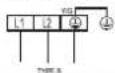
Type A
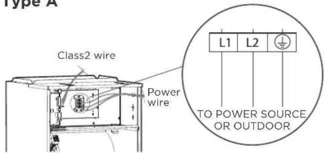
text_image
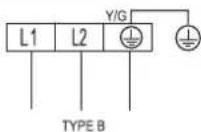
Type A Class2 wire Power wire L1 L2 TO POWER SOURCE OR OUTDOORType B
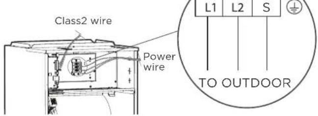
text_image
Class2 wire Power wire L1 L2 S TO OUTDOOR
WARNING
ISOLATE THE POWER SUPPLY LEADS AND COMMUNICATION LEADS BY THE STRAIN RELIF AND KEEP POWER SUPPLY LEADS AWAY FROM COMMUNICATION LEADS.
- Clamp down the cable with the cable clamp. The cable must not be loose or pull on the u-lugs.
- Reattach the electric box cover.
- Clamp down the cable with the cable clamp. The cable must not be loose or pull on the u-lugs.
- Reattach the electric box cover

CAUTION
- While connecting the wires, please strictly follow the wiring diagram.
- The refrigerant circuit can become very hot. Keep the interconnection cable away from the copper tube.
SPECIFIC WIRING METHODS

WARNING
Please refer to the wiring nameplate for the wiring method. Do not connect the power cord to the communication line, as this may damage the system.
Connection method A: Connection method B:
Refer to the wiring method of internal and external machine communication and wired controller as follows:
(A)
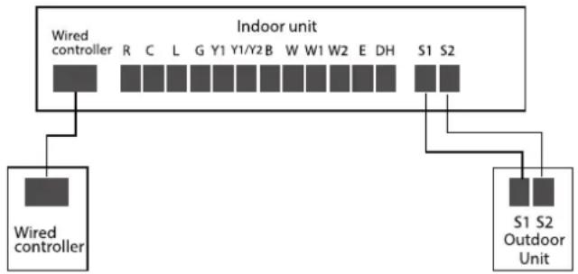
flowchart
graph TD
    A["Indoor unit"] --> B["Wired controller"]
    A --> C["S1 S2 Outdoor Unit"]
    B --> D["R"]
    B --> E["C"]
    B --> F["L"]
    B --> G["G"]
    B --> H["Y1"]
    B --> I["Y1/Y2"]
    B --> J["B"]
    B --> K["W"]
    B --> L["W1"]
    B --> M["W2"]
    B --> N["E"]
    B --> O["DH"]
    B --> P["S1"]
    B --> Q["S2"]
(B)

flowchart
graph TD
    A["Indoor unit"] --> B["Wired controller"]
    A --> C["L1(1) L2(2) S(3)"]
    A --> D["L1(1) L2(2) S(3) Outdoor Unit"]
    B --> E["Terminal R"]
    B --> F["Terminal C"]
    B --> G["Terminal L"]
    B --> H["Terminal G"]
    B --> I["Terminal Y1"]
    B --> J["Terminal Y1/Y2"]
    B --> K["Terminal B"]
    B --> L["Terminal W"]
    B --> M["Terminal W1"]
    B --> N["Terminal W2"]
    B --> O["Terminal E"]
    B --> P["Terminal DH"]
To use a 24V thermostat, you need to refer to the following wiring:
(A)
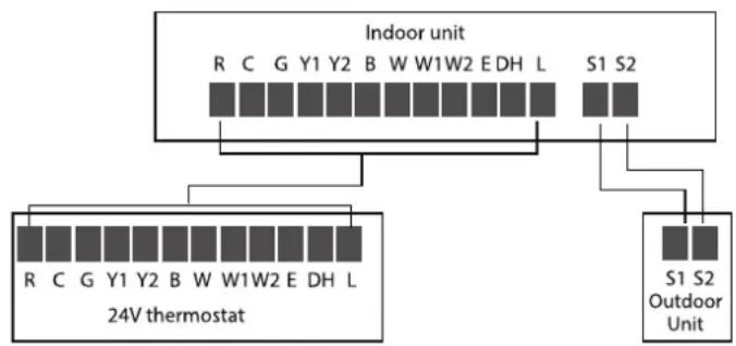
flowchart
graph TD
    A["Indoor unit"] --> B["24V thermostat"]
    B --> C["R C G Y1 Y2 B W W1W2 E DH L S1 S2"]
    A --> D["S1 S2 Outdoor Unit"]
    style A fill:#f9f,stroke:#333
    style B fill:#ccf,stroke:#333
    style C fill:#cfc,stroke:#333
    style D fill:#fcc,stroke:#333
(B)

flowchart
graph TD
    A["Indoor unit"] --> B["24V thermostat"]
    A --> C["L1(1)L2(2)S(3)"]
    A --> D["L1(1)L2(2)S(3) Outdoor Unit"]
    B --> E["R C G Y1 Y2 B W W1W2 E DH L"]
    C --> F["L1(1)L2(2)S(3)"]

NOTICE
The wiring method of the thermostat and the internal machine refers to the wiring of the non-communication scheme.
Connection method C:
Cooling and Fixed-speed Type Only System Wiring Diagram:
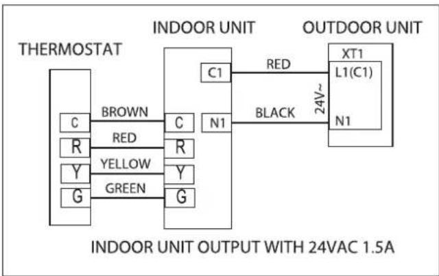
flowchart
graph LR
    A["INDOOR UNIT"] --> B["THERMOSTAT"]
    B --> C["BROWN"]
    B --> D["RED"]
    B --> E["Y"]
    B --> F["GREEN"]
    B --> G["C1"]
    B --> H["N1"]
    B --> I["BLACK"]
    I --> J["OUTDOOR UNIT"]
    J --> K["XT1"]
    J --> L["L1(C1)"]
    J --> M["N1"]
    N["INDOOR UNIT OUTPUT WITH 24VAC 1.5A"]

NOTICE
Suggestion: It is suggested that you use was a thermostat from Honeywell, series of non-programmabled thermostats, including the TH5220D.
Optional function wiring:
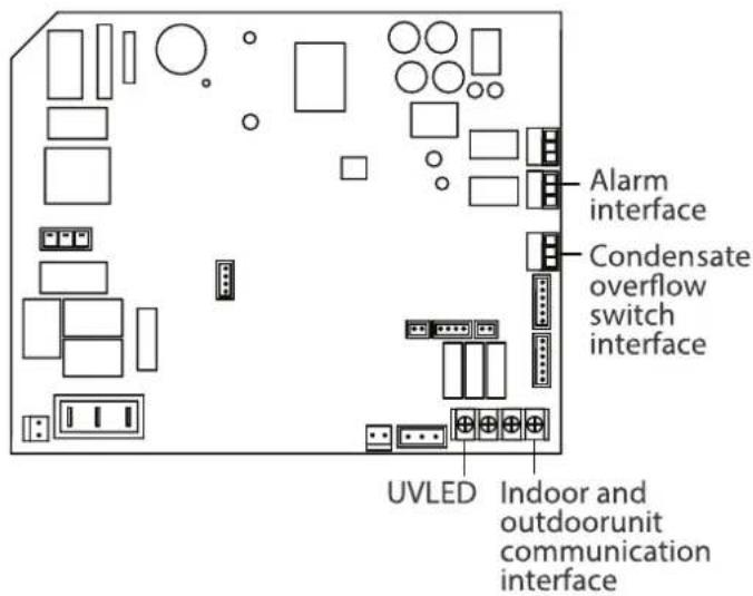
text_image
Alarm interface Condensate overflow switch interface UVLED Indoor and outdoorunit communication interfaceCondensate overflow switch:
The unit will accommodate a remote condensate overflow switch. To enable, remove jumper J1, and connect the installer provided condensate overflow device to CN5 per below. When an overflow condition is present, the device should open connection signaling the unit to turn o the system.
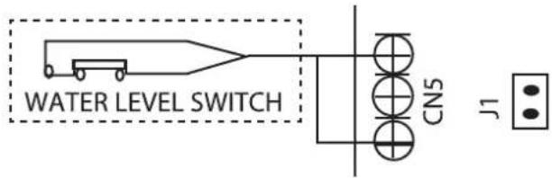
text_image
WATER LEVEL SWITCH CN5 J1The fault warning:
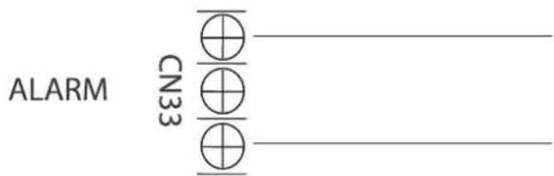
text_image
ALARM CN33Alarm output:
An alarm output (CN33) can be utilized if actions are required when a fault is present. This is a passive outlet port, so you will need to input a voltage signal. The relay is normally-open for normal operation, and closed when a fault condition is active.
Humidifier control:
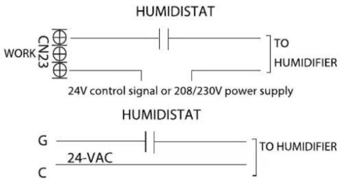
text_image
HUMIDISTAT WORK CN23 TO HUMIDIFIER 24V control signal or 208/230V power supply HUMIDISTAT G TO HUMIDIFIER C 24-VACTo connect a humidifier, utilize the passive signal "WORK" output (CN23) port as well as the G and C wires on the controller, and wire the humidistat and humidifier per above wiring diagram. When the fan is running, the CN23 relay will be closed, which will allow power to the humidifier when the humidistat is below humidity setpoint. If the thermostat or zone controller has an HUM interface, connect the humidifier directly to the HUM and C ports.
Dehumidification control wiring

text_image
S4 ON 1 2 DH R HUMIDISTATDehumidification control requires external Humidistat at DH and R. Set S4-2 as OFF. When the humidity rises and exceeds the set value of the Humidistat, the 24V signal of DH changes to OV, the cooling system starts the dehumidification operation, and the air volume drops to 80% of the nominal cooling air volume.
UV, fresh air or ion generator wiring

text_image
work CN23 UV, fresh air or ion generator, etc24V control signal or 208/230V power supply
The WORK port is linked with the fan. When the fan is running, the relay is closed; if an active 24V signal is required, it can be directly connected to the G and C ports.
Control logic
Indoor unit connector
| Connector | Purpose |
| R | 24V Power Connection |
| C | Common |
| G | Fan Control |
| Y1 | Low Cooling |
| Y/Y2 | High Cooling |
| B | Heating Reversing Valve |
| W | Heating control |
| W1 | Stage 1 Electric Heating |
| W2 | Stage 2 Electric Heating |
| E/AUX | Emergency Heating |
| DH/DS/BK | Dehumidification/Zoning control |
| L | System Fault Signal |
LED display
The control displays unit status as well as any active fault codes on the LED display. If the unit is functioning normally, the LED will display current temperature setpoint. When a fault code is active, the display will flash quickly the active fault code. Please refer to the fault code table located in the troubleshooting section of the manual for detailed fault code information.
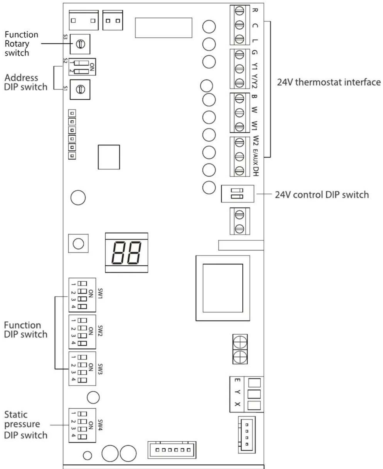
text_image
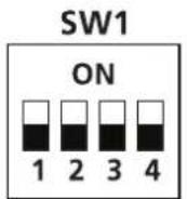
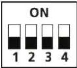
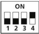
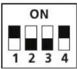
Function Rotary switch Address DIP switch 24V thermostat interface 24V control DIP switch Function DIP switch Static pressure DIP switchFunction DIP switch settings: Function combination table of SW1-1 and SW1-4:
The 24V thermostat mode needs to refer to the following settings:


| SW4-1 | 000 is the default 000/001/010/011/100/101/110/111,internal machines with different abilities, electric heating and PSC classification for use. |
| SW4-2 | |
| SW4-3 |
Indoor unit dial code
| Control typeSW | Stand alone or full system | |
 | Free match Free match | |
 | Wired controller | Full system |
 | 24V Thermostat | Full system |
 | 24V Thermostat | Stand alone |
| No. | Dial Code | Control Scenario | Function ON OFF Note | |||
| 1 SW1-2 1,2 Anti-cold blow protection option NO [Default] YES | ||||||
| 2 | SW1-3 | 1,2,3 | Single cooling / heating and and cooling options | Cooling | [Default] Cooling & Heating | |
| 3 SW2-1 | 1 | Compressor Running (demand working with heat pump+ Electric heat) | Compressor slower speed | [Default] Faster Compressor | Only affects compressor and W1 | |
| 4 SW2-1 | 2 | Temperature differential to activate first stage auxiliary heat(the GAP of T1 and Ts),Wire controller demand with heat pump+Electric heat working together | 2°F °C | °F °C | ||
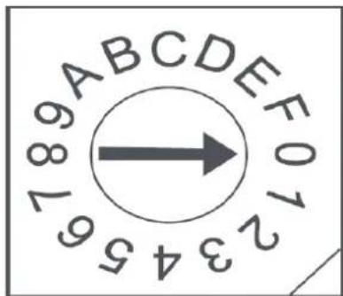
| 5 | SW2-2 | 2 | Electric heat on delay | YES | [Default]NO | |
| 6 | SW2-3 | 2 | Electric auxiliary heating delay to start time | 30 minutes | [Default] 15 minutes | Based on SW2-2 is ON |
| 7 SW2-4 | 2 | Compressor/Auxiliary heat outdoor ambient lockout | The compressor will not operate if the outdoor temperature is lower than the temperature represented by S3 | [Default] The heater will not operate if the outdoor temperature is greater than the temperature represented by S3 | SW2-4 and S3 need to working together | |
| 8 | Rotary Switch S3 | 2 | Set outdoor temperature Limitation (for auxiliary heating or compressor) | 0 means that the temperature protection is not turned on, the dial range is 1 through F, 1 equals -4°F and it increased up to 46°F based on table "A" | ||
| 9 SW3-1 | 1 | Maximum continuous runtime allowed before system automatically stages up capacity to satisfy set point. This adds 1 to 5°F to the user set point in the calculated control point to increase capacity and satisfy user set point | 30 minutes | [Default] 90 minutes | ||
| 10 | SW3-2 | 1 | Cooling and heating Y/Y2 temperature differential adjustment. | Compressor slower speed | [Default] Faster Compressor | Only affects compressor |
| 11 | SW3-3 | 1 | Compressor Running (demand working with heat pump+ Electric heat) | Compressor slower speed | [Default] Faster Compressor | Only affects compressor and W2 |
| 12 | SW3-3 | 2 | Temperature differential to activate second stage auxiliary heating(the GAP of T1 and Ts)Wire controller demand with heat pump+Electric heat working together | 4°F °C | °F °C | |
| 13 | SW3-4 1,3 | Fan speed of cooling mode when 24V Thermostat is applied for | Turbo | High | ||
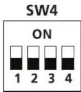
| 14 | SW4 | 1,2,3 | Electric heat nominal CFM adjustment | Available settings are 000/001/010/011. Each digit corresponds an individual swith position.For example [SW4-1 OFF, SW4-2 ON, SW4 -3 OFF] = 010See table 11 for the corresponding CFM adjustment | ||
| 15 | S4-1 | 1,3 | Default ON | [Default] For single stage supplemental heat, W1 and W2 are connected | For dual stage supplemental heat, W1 and W2 are controlled Independently. | |
| 16 | S4-2 | 1,3 | DH function selection | [Default] Dehumidification control not available | Dehumidification feature is enabled through thermostat | |
NOTICE: The SW4 DIP switch is only for Certified service technicians to debug and use, please do not touch it.
Table A
| Control Scenario | 24V Tstat, S1+S2 1 | |
| Wired Controller S1+S2 2 | ||
| Full 24V 3 |
text_image
123456987 186ABCCDEF01| S3 S3 ( ) S3 ( )F | °C | |
| 0 OFF OFF | ||
| 1 -4 -20 | ||
| 2 -0 -18 | ||
| 3 3 -16 | ||
| 4 7 -14 | ||
| 5 | 10 | -12 |
| 6 | 14 | -10 |
| 7 | 18 | -8 |
| 8 | 21 | -6 |
| 9 | 25 | -4 |
| A | 28 | -2 |
| B | 32 | 0 |
| C | 36 | 2 |
| D | 39 | 4 |
| E | 43 | 6 |
| F | 46 | 8 |
Outdoor unit DIP Switch setting
| NO. | Dial code | Features | ON | OFF |
| 1 | SW-1 | Metering device location | Outdoor throttling (normally closed single-way solenoid valve is not powered on) | Indoor throttling (normally closed single-way solenoid valve store) |
| 2 | SW-2 | Communication dial code | 24V communication scheme | 485 communication scheme |
| 3 | SW-3 | Strong cold and strong heat function | The cooling/heating target pressure compensation value is valid | The cooling/heating target pressure compensation value is invalid |
| 4 | SW-4 | Function to be defined |
Address DIP switch:
Address dialing S1+S2: When the user uses the centralized controller, the address dialing is required.
Network address: The address silkscreen is NET address, which is composed of a 16-bit address rotary code S2 plus a two-digit DIP switch S1 [Set during engineering installation, no network function does not need to be set] When S2 is 00 (the dialing code is not connected), the network address value is the value of S2; When S2 is 10 (corresponding to the switch of the hardware connected to the 10K resistor), the network address value is S2 plus 32; Determined by dial code S2 1-10K 2-5.1K When S2 is 01 (corresponding to the dial code of the 5.1K resistor connected to the hardware is turned on), the network address value is the value of S2 plus 16; When S2 is 11 (all dialing codes are on), the network address value is the value of S2 plus 48.
Determined by dial code S2 1-10K 2-5.1K
| Dial code selection | Website address | |
 | S2 + 48 | |
 | S2 + 32 | |
 | S2 + 16 | |
 | S2 | |

NOTICE
The SW4 DIP switch is only for Certified service technicians to debug and use, please do not touch it.
| Capacity | External Static Pressure Range | Fan speed Electric | heater kit | 24V thermostat Wired controller | Airflow volume (CFM) | |||
| DIP Switch | 24V terminal engaged DIP | Switch Mode | ||||||
| 0 - 0.80 in. w.g. | Cooling Turbo — SW3-4=ON Y2/Y — Cool 618 | |||||||
| Cooling High — SW3-4=OFF Y2/Y — Cool 576 | ||||||||
| Cooling Medium — — Y1 | — Cool 529 | |||||||
| Cooling Low | — — | — | — Cool 488 | |||||
| Heat Pump Turbo | — — | — | — Heat 565 | |||||
| Heat Pump High | — | — | B+Y2/Y, W | — | Heat | 541 | ||
| Heat Pump Medium | — | — | Y1 | — | Heat | 435 | ||
| Heat Pump Low | — | — | — | — | Heat | 400 | ||
| Electric heater kit 0(Default) | 10KW | SW4-1=OFF SW4-2=OFF SW4-3=OFF | W1, W2, AUX | SW4-1=OFF SW4-2=OFF SW4-3=OFF | Heat + AUX, AUX | 653 | ||
| Electric heater kit 1 10KW, 8KW | SW4-1=OFF SW4-2=OFF SW4-3=ON | W1, W2, AUX | SW4-1=OFF SW4-2=OFF SW4-3=ON | Heat + AUX, AUX | 624 | |||
| Electric heater kit 2 | 8KW | SW4-1=OFF SW4-2=ON SW4-3=OFF | W1, W2, AUX | SW4-1=OFF SW4-2=ON SW4-3=OFF | Heat + AUX, AUX | 594 | ||
| Electric heater kit 3 | 5KW, 3KW | SW4-1=OFF SW4-2=ON SW4-3=ON | W1, W2, AUX | SW4-1=OFF SW4-2=ON SW4-3=ON | Heat + AUX, AUX | 565 | ||
| 0 - 0.80 in. w.g. | Cooling Turbo — SW3-4=ON Y2/Y — Cool 824 | |||||||
| Cooling High — SW3-4=OFF Y2/Y — Cool 759 | ||||||||
| Cooling Medium — — Y1 | — Cool 694 | |||||||
| Cooling Low | — — | — | — Cool 629 | |||||
| Heat Pump Turbo | — | — | — | — | Heat | 788 | ||
| Heat Pump High | — | — | B+Y2/Y, W | — | Heat | 753 | ||
| Heat Pump Medium | — | — | Y1 | — | Heat | 641 | ||
| Heat Pump Low | — | — | — | — | Heat | 524 | ||
| Electric heater kit 0(Default) | 15KW | SW4-1=OFF SW4-2=OFF SW4-3=OFF | W1, W2, AUX | SW4-1=OFF SW4-2=OFF SW4-3=OFF | Heat + AUX, AUX | 871 | ||
| Electric heater kit 1 | 15KW, 10KW | SW4-1=OFF SW4-2=OFF SW4-3=ON | W1, W2, AUX | SW4-1=OFF SW4-2=OFF SW4-3=ON | Heat + AUX, AUX | 841 | ||
| Electric heater kit 2 | 10KW, 8KW | SW4-1=OFF SW4-2=ON SW4-3=OFF | W1, W2, AUX | SW4-1=OFF SW4-2=ON SW4-3=OFF | Heat + AUX, AUX | 818 | ||
| Electric heater kit 3 | 5KW | SW4-1=OFF SW4-2=ON SW4-3=ON | W1, W2, AUX | SW4-1=OFF SW4-2=ON SW4-3=ON | Heat + AUX, AUX | 788 | ||
| 0 - 0.80 in. w.g. | Cooling Turbo — SW3-4=ON Y2/Y — Cool 988 | |||||||
| Cooling High — SW3-4=OFF Y2/Y — Cool 894 | ||||||||
| Cooling Medium — — Y1 | — Cool 806 | |||||||
| Cooling Low | — — | — | — Cool 712 | |||||
| Heat Pump Turbo | — | — | — | — | Heat | 918 | ||
| Heat Pump High | — | — | B+Y2/Y, W | — | Heat | 876 | ||
| Heat Pump Medium | — | — | Y1 | — | Heat | 665 | ||
| Heat Pump Low | — | — | — | — | Heat | 453 | ||
| Electric heater kit 0(Default) | 15KW | SW4-1=OFF SW4-2=OFF SW4-3=OFF | W1, W2, AUX | SW4-1=OFF SW4-2=OFF SW4-3=OFF | Heat + AUX, AUX | 1088 | ||
| Electric heater kit 1 | 15KW, 10KW | SW4-1=OFF SW4-2=OFF SW4-3=ON | W1, W2, AUX | SW4-1=OFF SW4-2=OFF SW4-3=ON | Heat + AUX, AUX | 1029 | ||
| Electric heater kit 2 | 10KW, 8KW | SW4-1=OFF SW4-2=ON SW4-3=OFF | W1, W2, AUX | SW4-1=OFF SW4-2=ON SW4-3=OFF | Heat + AUX, AUX | 976 | ||
| Electric heater kit 3 | 5KW | SW4-1=OFF SW4-2=ON SW4-3=ON | W1, W2, AUX | SW4-1=OFF SW4-2=ON SW4-3=ON | Heat + AUX, AUX | 918 | ||
| Capacity | External Static Pressure Range | Fan Speed Electric | heater kit | 24V thermostat Wired controller | Airflowfl volume (CFM) | |||
| DIP Switch 24V terminal engaged DIP | Switch Mode | |||||||
| 36K | 0 - 0.80 in. w.g. | Cooling Turbo | — SW3-4=ON Y2/Y — Cool | 1188 | ||||
| Cooling High | — SW3-4=OFF Y2/Y — Cool | 1082 | ||||||
| Cooling Medium | — — Y1 — Cool | 971 | ||||||
| Cooling Low | — — | — | — Cool | 865 | ||||
| Heat Pump Turbo | — — | — | — Heat | 1112 | ||||
| Heat Pump High | — — | B+Y2/Y | W — Heat | 1059 | ||||
| Heat Pump Medium | — — Y1 — Heat | 794 | ||||||
| Heat Pump Low | — — | — | — Heat | 582 | ||||
| Electric heater kit 0(Default) | 20KW | SW4-1=OFF SW4-2=OFF SW4-3=OFF | W1, W2, AUX | SW4-1=OFF SW4-2=OFF SW4-3=OFF | Heat + AUX, AUX | 1306 | ||
| Electric heater kit 1 | 15KW | SW4-1=OFF SW4-2=OFF SW4-3=ON | W1, W2, AUX | SW4-1=OFF SW4-2=OFF SW4-3=ON | Heat + AUX, AUX | 1241 | ||
| Electric heater kit 2 | 10KW, 8KW | SW4-1=OFF SW4-2=ON SW4-3=OFF | W1, W2, AUX | SW4-1=OFF SW4-2=ON SW4-3=OFF | Heat + AUX, AUX | 1176 | ||
| Electric heater kit 3 | 5KW, 8KW | SW4-1=OFF SW4-2=ON SW4-3=ON | W1, W2, AUX | SW4-1=OFF SW4-2=ON SW4-3=ON | Heat + AUX, AUX | 1112 | ||
| 48K | 0 - 0.80 in. w.g. | Cooling Turbo | — SW3-4=ON Y2/Y — Cool | 1471 | ||||
| Cooling High | — SW3-4=OFF Y2/Y — Cool | 1282 | ||||||
| Cooling Medium | — — Y1 — Cool | 1094 | ||||||
| Cooling Low | — — | — | — Cool | 906 | ||||
| Heat Pump Turbo | — — | — | — Heat | 1471 | ||||
| Heat Pump High | — — | B+Y2/Y | W — Heat | 1306 | ||||
| Heat Pump Medium | — — Y1 — Heat | 1141 | ||||||
| Heat Pump Low | — — | — | — Heat | 976 | ||||
| Electric heater kit 0(Default) | 20KW | SW4-1=OFF SW4-2=OFF SW4-3=OFF | W1, W2, AUX | SW4-1=OFF SW4-2=OFF SW4-3=OFF | Heat + AUX, AUX | 1741 | ||
| Electric heater kit 1 | 15KW | SW4-1=OFF SW4-2=OFF SW4-3=ON | W1, W2, AUX | SW4-1=OFF SW4-2=OFF SW4-3=ON | Heat + AUX, AUX | 1653 | ||
| Electric heater kit 2 | 10KW, 8KW | SW4-1=OFF SW4-2=ON SW4-3=OFF | W1, W2, AUX | SW4-1=OFF SW4-2=ON SW4-3=OFF | Heat + AUX, AUX | 1559 | ||
| Electric heater kit 3 | 8KW | SW4-1=OFF SW4-2=ON SW4-3=ON | W1, W2, AUX | SW4-1=OFF SW4-2=ON SW4-3=ON | Heat + AUX, AUX | 1471 | ||
| 60K | 0 - 0.80 in. w.g. | Cooling Turbo | — SW3-4=ON Y2/Y — Cool | 1806 | ||||
| Cooling High | — SW3-4=OFF Y2/Y — Cool | 1582 | ||||||
| Cooling Medium | — — Y1 — Cool | 1359 | ||||||
| Cooling Low | — — | — | — Cool | 1135 | ||||
| Heat Pump Turbo | — — | — | — Heat | 1659 | ||||
| Heat Pump High | — — | B+Y2/Y | W — Heat | 1582 | ||||
| Heat Pump Medium | — — Y1 — Heat | 1247 | ||||||
| Heat Pump Low | — — | — | — Heat | 976 | ||||
| Electric heater kit 0(Default) | 25KW | SW4-1=OFF SW4-2=OFF SW4-3=OFF | W1, W2, AUX | SW4-1=OFF SW4-2=OFF SW4-3=OFF | Heat + AUX, AUX | 2171 | ||
| Electric heater kit 1 | 15KW, 20KW | SW4-1=OFF SW4-2=OFF SW4-3=ON | W1, W2, AUX | SW4-1=OFF SW4-2=OFF SW4-3=ON | Heat + AUX, AUX | 2029 | ||
| Electric heater kit 2 | 10KW, 15KW | SW4-1=OFF SW4-2=ON SW4-3=OFF | W1, W2, AUX | SW4-1=OFF SW4-2=ON SW4-3=OFF | Heat + AUX, AUX | 1894 | ||
| Electric heater kit 3 | 10KW | SW4-1=OFF SW4-2=ON SW4-3=ON | W1, W2, AUX | SW4-1=OFF SW4-2=ON SW4-3=ON | Heat + AUX, AUX | 1753 | ||

NOTICE
The constant airflow volume motor is applied. So the airflow volume is constant at all ESP within stated range.
POWER SPECIFICATIONS
Cooling and Heating power specifications(for North America models)
| MODEL(Btu/h) | 18K 24K | 30K | |||
| POWER(outdoor) | PHASE | 1 Phase | |||
| FREQUENCY AND VOLT | 208/230V,60Hz | ||||
| INPUT CIRCUIT FUSE | INDOOR UNIT(A) 6.3A 6.3A 6.3A OUTDOOR UNIT(A) 30A 30A 30A | ||||
| LINES GAUGE | OUTDOOR UNIT POWER LINE | LINE QUANTITY | 2+Ground | ||
| LINE DIAMETER(AWG) | 14 12 | 12 | |||
| OUTDOOR-INDOOR SIGNAL LINE | LINE QUANTITY | —— | |||
| LINE DIAMETER(AWG) | —— | ||||
| THERMOSTAT SIGNAL LINE | LINE QUANTITY | —— | |||
| LINE DIAMETER(AWG) | 18 | ||||
| INDOOR-OUTDOOR CONNECTION LINE | LINE QUANTITY | 4 | |||
| LINE DIAMETER(AWG) | 16 | ||||
| MODEL(Btu/h) | 36K | 48K | 60K | ||
| POWER(outdoor) | PHASE | 1 Phase | |||
| FREQUENCY AND VOLT | 208/230V,60Hz | ||||
| INPUT CIRCUIT FUSE | INDOOR UNIT(A) 16A 16A 16A | 60A 60A 60AOUTDOOR UNIT(A) | |||
| LINES GUGE | OUTDOOR UNIT POWER LINE | LINE QUANTITY | 2+Ground | ||
| LINE DIAMETER(AWG) | STD 12HH 8 | STD 10HH 8 | STD 10HH NA | ||
| OUTDOOR-INDOOR SIGNAL LINE | LINE QUANTITY | 2 | |||
| LINE DIAMETER(AWG) | 20 | ||||
| THERMOSTAT SIGNAL LINE | LINE QUANTITY | —— | |||
| LINE DIAMETER(AWG) | 18 | ||||
| INDOOR-OUTDOOR CONNECTION LINE | LINE QUANTITY | 3 | |||
| LINE DIAMETER(AWG) | 16 | ||||
AIR EVACUATION
NOTICE
When opening valve stems, turn the hexagonal wrench until it hits against the stopper. Do not try to force the valve to open further.
Preparations and precautions
Air and foreign matter in the refrigerant circuit can cause abnormal rises in pressure, which can damage the air conditioner, reduce its efficiency, and cause injury. Use a vacuum pump and manifold gauge to evacuate the refrigerant circuit, removing any non-condensable gas and moisture from the system. Evacuation should be performed upon initial installation and when unit is relocated.
BEFORE PERFORMING EVACUATION
√ Check to make sure the connective pipes between the indoor and outdoor units are connected properly.
☑ Check to make sure all wiring is connected properly.
Evacuation Instructions
- Connect the charge hose of the manifold gauge to service port on the outdoor unit's low pressure valve.
- Connect another charge hose from the manifold gauge to the vacuum pump.
- Open the Low Pressure side of the manifold gauge. Keep the High Pressure side closed.
- Turn on the vacuum pump to evacuate the system.
- Run the vacuum for at least 15 minutes, or until the Compound Meter reads -750 Micron HG(-10Pa).
Outdoor unit
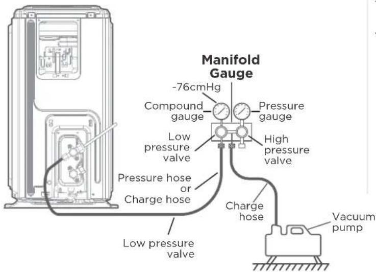
text_image
Manifold Gauge -76cmHg Compound gauge Pressure gauge Low pressure valve High pressure valve Pressure hose or Charge hose Charge hose Low pressure valve Vacuum pump- Close the Low Pressure side of the manifold gauge, and turn off the vacuum pump.
- Wait for 5 minutes, then check that there has been no change in system pressure.
- If there is a change in system pressure, refer to Gas Leak Check section for information on how to check for leaks. If there is no change in system pressure, unscrew the cap from the packed valve (high pressure valve).
- Insert hexagonal wrench into the packed valve (high pressure valve) and open the valve by turning the wrench in a 1/4 counterclockwise turn. Listen for gas to exit the system, then close the valve after 5 seconds.
- Watch the Pressure Gauge for one minute to make sure that there is no change in pressure. The Pressure Gauge should read slightly higher than atmospheric pressure.
- Remove the charge hose from the service port.

text_image
Flare nut valve body valve stem Cap- Using hexagonal wrench, fully open both the high pressure and low pressure valves.
- Tighten valve caps on all three valves (service port, high pressure, low pressure) by hand. You may tighten it further using a torque wrench if needed.
NOTE ON ADDING REFRIGERANT

CAUTION
DO NOT mix refrigerant types.
Some systems require additional charging depending on pipe lengths. The standard pipe length varies according to local regulations. For example, in North America, the standard pipe length is 7.5m (25'). In other areas, the standard pipe length is 5m (16'). The refrigerant should be charged from the service port on the outdoor unit's low pressure valve. The additional refrigerant to be charged can be calculated using the following formula:
| Liquid Side Diameter | |||
| 6.35(1/4") | 9.52(3/8") | 12.7(1/2") | |
| R410A:(metering device in the indoor unit) | (Total pipe length-standard pipe length)x30g(0.32oZ)/m(ft) | (Total pipe length-standard pipe length)x65g(0.69oZ)/m(ft) | (Total pipe length-standard pipe length)x115g(1.23oZ)/m(ft) |
| R410A:(metering device in the outdoor unit) | (Total pipe length-standard pipe length)x15g(0.16oZ)/m(ft) | (Total pipe length-standard pipe length)x30g(0.32oZ)/m(ft) | (Total pipe length-standard pipe length)x65g(0.69oZ)/m(ft) |
| R32 : | (Total pipe length-standard pipe length)x12g(0.13oZ)/m(ft) | (Total pipe length-standard pipe length)x24g(0.26oZ)/m(ft) | (Total pipe length-standard pipe length)x40g(0.42oZ)/m(ft) |
TEST RUN

CAUTION
Failure to perform the test run may result in unit damage, property damage, or personal injury.
Before test run
A test run must be performed after the entire system has been completely installed. Confirm the following points before performing the test:
a) Indoor and outdoor units are properly installed.
b) Piping and wiring are properly connected.
c) No obstacles near the inlet and outlet of the unit that might cause poor performance or product malfunction.
d) Refrigeration system does not leak.
e) Drainage system is unimpeded and draining to a safe location.
f) Insulation of piping and duct is properly installed.
g) Grounding wires are properly connected.
h) Length of the piping and additional refrigerant capacity have been recorded.
i) Power voltage is the correct voltage for the air conditioner
Test run instructions
- Open both the liquid and gas service valves.
- Turn on the main power switch and allow the unit to warm up.
- Set the air conditioner to COOL mode.
- For the Indoor Unit
a. Double check to see if the room temperature is being registered correctly.
b. Ensure the manual buttons on the indoor unit works properly.
c. Check to see that the drainage system is unimpeded and draining smoothly.
d. Ensure there is no vibration or abnormal noise during operation.
- For the Outdoor Unit
a. Check to see if the refrigeration system is leaking.
b. Make sure there is no vibration or abnormal noise during operation.
c. Ensure the wind, noise, and water generated by the unit do not disturb your neighbors or pose a safety hazard.
- Drainage Test
a. Ensure the drainpipe flows smoothly. New buildings should perform this test before finishing the ceiling.
b. Turn on the main power switch and run the air conditioner in COOL mode.
c. Check to see that the water is discharged. It may take up to one minute before the unit begins to drain depending on the drainpipe.
d. Make sure that there are no leaks in any of the piping.
e. Stop the air conditioner. Turn off the main power switch and reinstall the test cover.

NOTICE
If the unit malfunctions or does not operate according to your expectations, please refer to the Troubleshooting section of Service Manual before calling customer service.
The design and specifications are subject to change without prior notice for product improvement.
Consult with the sales agency or manufacturer for details. Any updates to the manual will be uploaded to the service website, please check for the latest version.
24V SIGNAL CHART
| 24V input terminal | ||||||||||||
| Mode | Priority G | Y1 Y/Y2 B | W W1 W2 E | AUX DH/DS | /BK Fan speed | Display | ||||||
| OFF | /0 0 0 | 0 0 0 0 0 | * | OFF | ||||||||
| FAN | 7 | 1 0 0 | * | 0 0 0 0 | 1 | * | Low | |||||
| Cooling stage 1 | 6 | * | 1 0 0 0 | 0 0 0 1 Mid | 2 | |||||||
| Cooling stage 2 | * | * | 1 0 0 0 | 0 0 1 | High | 3 | ||||||
| Dehumidification | * | 1 0 0 0 | 0 0 0 0 Low | 4 | ||||||||
| Dehumidification | * | * | 1 0 0 0 | 0 0 0 Low 5 | ||||||||
| Heat pump stage 1 | 5 | * | 1 0 1 0 | 0 0 0 1 Mid | 6 | |||||||
| Heat pump stage 2 | * | * | 1 1 0 0 | 0 0 1 | High | 7 | ||||||
| Heat pump stage 2 | ** | ** | 1 0 0 0 | 1 | High | |||||||
| Electric heater kit 1 | 3 | * | 0 | 0 | * | 0 1 0 0 | * | Turbo | 8 | |||
| Electric heater kit 2 | * | 0 | 0 | * | 0 0 1 0 | * | Turbo | |||||
| Electric heater kit 1 and kit 2 | * | 0 | 0 | * | 0 1 1 0 | * | Turbo 9 | |||||
| Heat pump stage 1 + Electric heater kit 1 | 4 | * | 1 0 1 0 | 1 0 0 1 | Turbo | 10 | ||||||
| Heat pump stage 1 + Electric heater kit 2 | * | 1 0 1 0 | 0 1 0 1 | Turbo | ||||||||
| Heat pump stage 2 + Electric heater kit 1 | * | * | 1 1 0 1 | 0 0 1 | Turbo | |||||||
| Heat pump stage 2 + Electric heater kit 1 | ** | ** | 1 1 0 0 | 1 | Turbo | |||||||
| Heat pump stage 2 + Electric heater kit 2 | * | * | 1 1 0 0 | 1 0 1 | Turbo | |||||||
| Heat pump stage 2 + Electric heater kit 2 | ** | ** | 1 0 1 0 | 1 | Turbo | |||||||
| Heat pump stage 1 + Electric heater kit 1 and kit 2 | * | 1 0 1 0 | 1 1 0 1 | Turbo | 11 | |||||||
| Heat pump stage 2 + Electric heater kit 1 and kit 2 | * | * | 1 1 0 1 | 1 0 1 | Turbo | |||||||
| Heat pump stage 2 + Electric heater kit 1 and kit 2 | ** | ** 1 | 1 1 0 1 Turbo | |||||||||
| Emergency heat | 1 | ** | ** | ** | * | 1 | * | Turbo | 12 | |||
| Heating zone control | 2 | * | 1 0 1 0 | * | * | 0 0 Low | 13 | |||||
| Heating zone control | * | * | 1 1 0 | * | * | 0 0 Low | ||||||
| Heating zone control | ** | ** | 1 | * | * | 0 0 Low | ||||||
| Heating zone control | * | 0 | 0 | * | 0 1 0 0 | 0 Low | ||||||
| Heating zone control | * | 0 | 0 | * | 0 0 1 0 | 0 Low | ||||||
| Heating zone control | * | 0 | 0 | * | 0 1 1 0 | 0 Low | ||||||
| Note:1: 24V signal0: No 24V signal*: 1 or 0.The AUU will turn off if the 24V input cannot meet the table. | ||||||||||||
Matching With Multi Zone Outdoor Unit
When matching with multi zone outdoor unit, the indoor unit cannot be started due to the mode conflict in the following cases.
| Mode Of AHU Mode Of other IDU zones Mode Conflict Unit | ||
| Fan | Heating/ Electric heat/Emergency heat | AHU |
| Cooling | AHU | |
| Dehumidification | AHU | |
| Heating | Fan/Cooling/Dehumidification | Other IDU zones |
| Electric heat | Other IDU zones | |
| Emergency heat | Other IDU zones | |
| Note:When Heating reaches the temperature and shuts down with other IDU zones heating normally, the AHU fan will stop running, and the Fan-ON mode is invalid.The heat pump will start synchronously when Emergency heat or Electric heat is started.When two AHU units are connected by multi zone outdoor unit, the above rules are applicable while one of the AHU unit regarded as other IDU zones. | ||