
MHS60S - Range hood MIDEA - Free user manual and instructions
Find the device manual for free MHS60S MIDEA in PDF.


| Product Type | Range hood (cooker hood) |
| Brand | Midea |
| Model | MHS60S |
| Dimensions (W x D x H) | 423 mm x 88 mm (body) |
| Minimum Installation Height | 650 mm above cooking surface |
| Exhaust Pipe Diameter | 120 mm or 150 mm |
| Number of Motors | 2 (double motor) |
| Fan Speeds | 2 (Low and High) |
| Lighting | LED module, 3W, 220-240V, E14 base |
| Controls | Sliding switch (motor off/low/high, light on/off) |
| Operating Modes | Ducted (exhaust) or recirculation (with charcoal filter) |
| Air Discharge | External (ducted) or internal (recirculation) |
| Grease Filter Type | Metal self-supporting, washable |
| Grease Filter Cleaning | Every 2 months (or more often for heavy use), dishwasher safe |
| Charcoal Filter Type | Activated charcoal, not washable |
| Charcoal Filter Replacement | Every 4 months (or more often for heavy use) |
| Max Number of Hob Elements | 4 |
| Electrical Supply | 230V ~ 50Hz (typical, check rating plate) |
| Safety Features | Anti-backflow valve, earthing required, thermal cut-out |
| Included Accessories | Check valve, screws, wall plugs, charcoal filter (optional) |
| Disposal | EU WEEE directive – separate collection required |
Frequently Asked Questions - MHS60S MIDEA
User questions about MHS60S MIDEA
0 question about this device. Answer the ones you know or ask your own.
Ask a new question about this device
Download the instructions for your Range hood in PDF format for free! Find your manual MHS60S - MIDEA and take your electronic device back in hand. On this page are published all the documents necessary for the use of your device. MHS60S by MIDEA.
USER MANUAL MHS60S MIDEA
natural_image
Exterior view of a white air conditioner unit with ventilation slots and a recessed panel (no text or symbols visible)
SAVE THESE INSTRUCTIONS CAREFULLY
Read these instructions carefully before using your cooker hood, and keep it carefully. If you follow the instructions, your cooker hood will provide you with many years of good service.

The instructions for Use apply to several versions of this appliance. Accordingly, you find descriptions of individual features that do not apply to your specific appliance.
INSTALLATION
● The manufacturer will not be held liable for any damages resulting from incorrect or improper installation.
● The minimum safety distance between the cooker top and the extractor hood is 650 mm (some models can be installed at a lower height, please refer to the paragraphs on working dimensions and installation).
- Check that the mains voltage corresponds to that indicated on the rating plate fixed to the inside of the hood.
- For Class I appliances, check that the domestic power supply guarantees adequate earthing.
- Connect the extractor to the exhaust flue through a pipe of minimum diameter 120mm. The route of the flue must be as short as possible.
- Do not connect the extractor hood to exhaust ducts carrying combustion flumes (boilers, fireplaces, etc.).
- If the extractor is used in conjunction with non-electrical appliances (e.g. gas burning appliances), a sufficient degree of aeration must be guaranteed in the room in order to prevent the backflow of exhaust gas. The kitchen must have an opening communicating directly with the open air in order to guarantee the entry of clean air. When the cooker hood is used in conjunction with appliances supplied with energy other than electric, the negative pressure in the room must not exceed 0,04 mbar to prevent fumes being drawn back into the room by the cooker hood.
- In the event of damage to the power cable, it must be replaced by the manufacturer or by the technical service department, in order to prevent any risks.
- If the instructions for installation for the gas hob specify a greater distance specified above, this has to be taken into account. Regulations concerning the discharge of air have to be fulfilled.
USE
● The extractor hood has been designed exclusively for domestic use to eliminate kitchen smells.
● Never use the hood for purposes other than for which it has been designed.
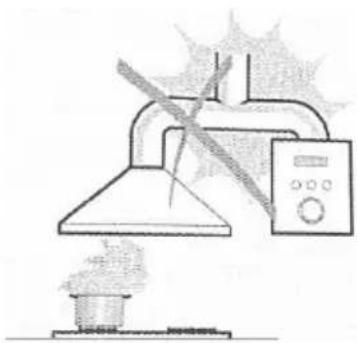
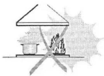
● Never leave high naked flames under the hood when it is in operation.
- Adjust the flame intensity to direct it onto the bottom of the pan only, making sure that it does not engulf the sides.
- Deep fat fryers must be continuously monitored during use: overheated oil can burst into flames.
● Do not flame under the range hood; risk of fire.
- This appliance can be used by children aged from 8 years and above and persons with reduced physical, sensory or mental capabilities or lack of experience and knowledge if they have been given supervision or instruction concerning use of the appliance in a safe way and understand the hazards involved.
● Children should be supervised to ensure that they do not play with the appliance.
● Cleaning and user maintenance shall not be made by children without supervision.
● "CAUTION: Accessible parts may become hot when used with cooking appliances".
MAINTENANCE
- Switch off or unplug the appliance from the mains supply before carrying out any maintenance work.
● Clean and/or replace the Filters after the specified lime period (Fire hazard).
● Clean the hood using a damp cloth and a neutral liquid detergent.
● The appliance uses 4 hob elements at most.

The symbol is packaging indicates that this product may not be treated as household waste. Instead it shall be handed over to the applicable collection point for the recycling of electrical and electronic equipment. By ensuring this product is disposed of correctly, you will help prevent potential negative consequences for the environment and human health, which could otherwise be caused by inappropriate waste handling of this product. For more detailed information about recycling of this product, please contact your local city office, your household waste disposal service or the shop where you purchased the product.
natural_image
Simple line drawing of a laboratory setup with a conical flask, heating element, and control panel (no text or symbols)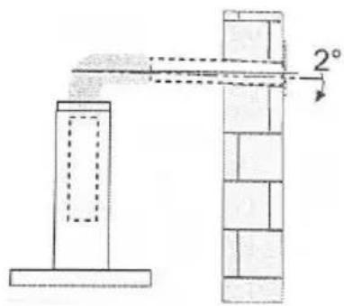
natural_image
Simple line drawing of a campfire setup with a stove and fire, no text or symbols present| Ref. | Qty. | Product Components |
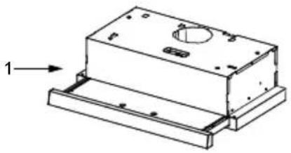
| 1 | 1 | Hood Body, complete with: Controls, Light, Blower, Filter. |
| 2 | 1 | Check valve |
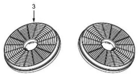
| 3 | 2 | The Activated Charcoal filter (1 / 2 optional) |
| 4 | 4 | Screws 5×50 |
| 5 | 4 | Wall Plugs |
natural_image
Technical line drawing of a mechanical housing or enclosure with mounting base and internal components (no text or symbols)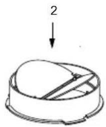
natural_image
Simple line drawing of a dome-shaped object with a downward arrow labeled '2' pointing to its top surface (no text or symbols beyond the number)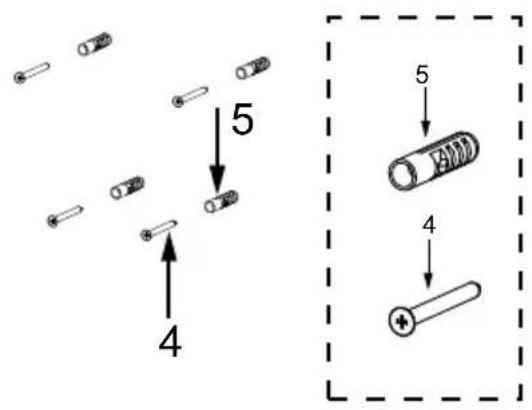
natural_image
Two circular fan-like structures with radial blades, one labeled with number 3 (no text or symbols on the fan itself)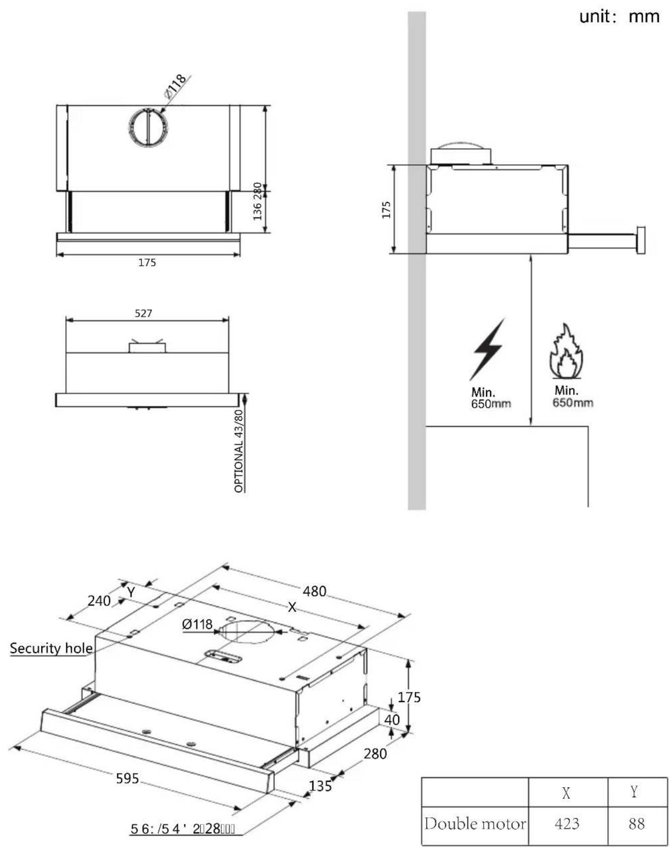
| X | Y | |
| Double motor | 423 | 88 |
METHOD 1
natural_image
Technical line drawing of a mechanical housing assembly with mounting brackets and internal components (no text or symbols)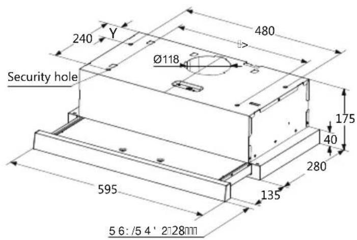
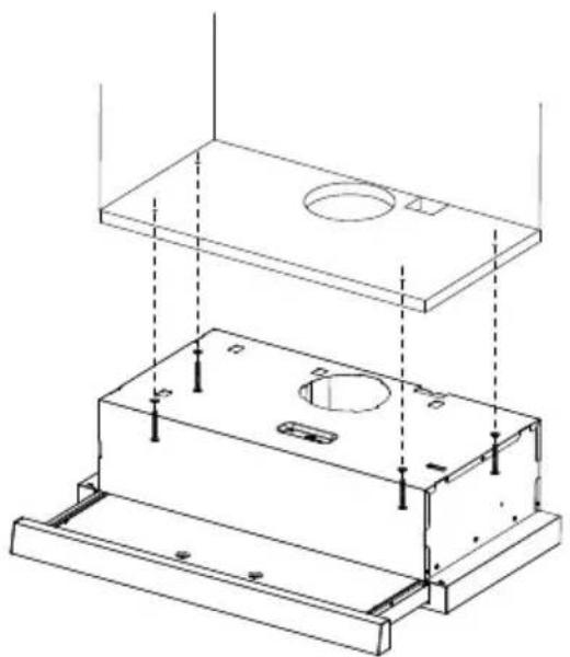
- According to the figure, make sure the position of hood in the cabinet. The wood strips should be line up with the 4 keyholes slots on the top of the range hood. On the cabinet, install 4 screws (supplied) according to the relative position of 4 key holes on the bottom of hood. The extent of screwing should be convenience to the next installation.
●Hang the hood and let it's 4 key holes aim at screws, the 4 screws should be in the narrow parts of key holes. Screws should be fasten firmly, make sure that the installation between the hood and cabinet is enough fasten.
● Install screws in the security holes, in case of front and back moving of hood, so that the using is safer.

Information
When cutting or drilling into wall or ceiling, do not damage electrical wiring or other hidden utilities.
METHOD 2
natural_image
Technical line drawing of a mechanical housing or enclosure with mounting base and internal components (no text or symbols)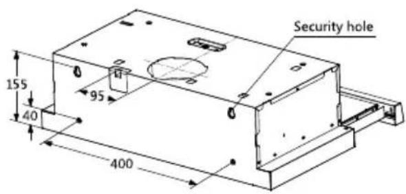
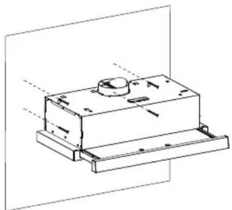
z In the installation surface in cabinet don't adapt to install the cooker hood, then as per fig, fix the position of cooker hood on the wall.
z ☐ On the wall, install 2 screws ( supplied ) according to the relative position of 2 key holes on the back of hood.
z The extent of screwing should be convenience to the next installation.
z Also install screws in the security holes, in case of front and back moving of hood, so that the using is safer.
Installation of hoods built in combi cabinets is the same as previous method.

Information
Congratulations on the purchase our cooker hood which is designed to include many superior features that permit you the fullest expression of your living. Before installing and/or using the cooker hood carefully read all the instruction.
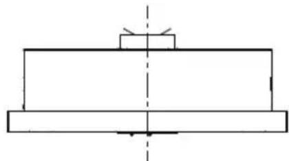
natural_image
Pure mechanical assembly diagram showing two stacked plates with a central shaft and alignment lines (no text or symbols)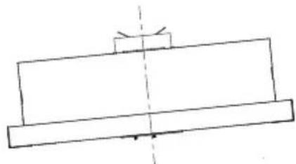
natural_image
Simple line drawing of a mechanical component with a central axis and two horizontal plates (no text or symbols)Right Wrong

Information
The cooker hood must not be installed and connected to flues where other appliances are installed and which run off other energy supplied different to electricity(water heater boiled cookers(range/agas)etc.).
CONNECTIONS
DUCTED VERSION AIR EXHAUST SYSTEM
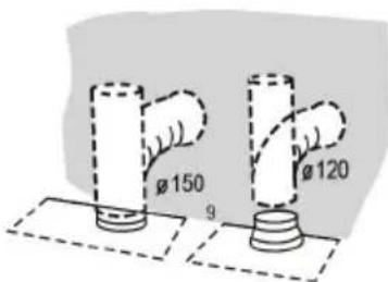
When installing the ducted version, connect the hood to the chimney using either a flexible or rigid pipe 150 or 120 mm, the choice of which is left to the installer.
- To install a 120 mm air exhaust connection, insert the reducer flange 3 on the hood body outlet.
● Fix the pipe 4 in position using sufficient pipe clamps (not supplied). - Remove possible charcoal filters.
Operation
Check beforehand
Check the safe condition of the appliance:
- Check whether there are visible defects.
- Check that all parts of the appliance have been securely fitted.
Switching on/off
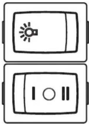
● In the right part of the cooker hood.
● There are 2 speeds for the motor and on off switch of the lamp.
- Locker switch for operation.
Motor Operation
• [ ○]=Off
• [ ]=Low Power Setting
• [ ||]=High Power Setting
Light Operation
• [ ]=Off
• [☀️]=On
natural_image
Two identical rectangular panels with a central icon: one with a light bulb and another with two circular symbols (no text or labels)CHECK VALVE INSTALLATION
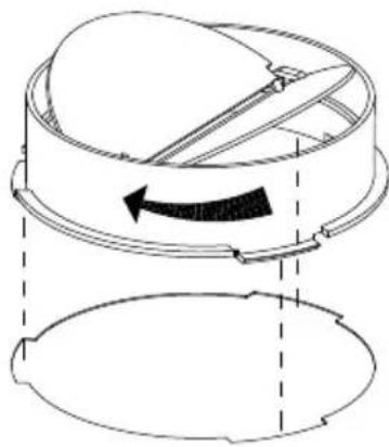
Hold on check valve with your hands, align the box gap, put in the check valve, and then spin to a certain angle until three angles of the valve are stuck. Installation is complete.
natural_image
Technical line drawing of a mechanical component with an arrow indicating rotation or movement (no text or symbols)GREASE FILTERS
CLEANING METAL SELF-SUPPORTING GREASE FILTERS
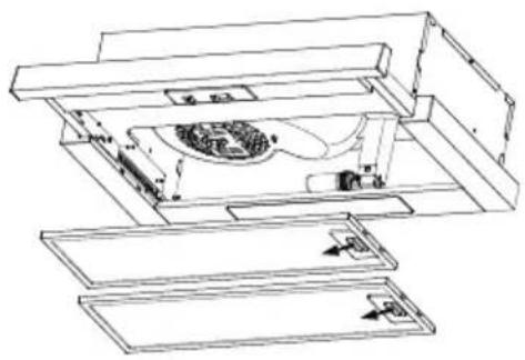
- The filters must be cleaned every 2 months of operation, or more frequently for particularly heavy usage, and can be washed in a dishwasher.
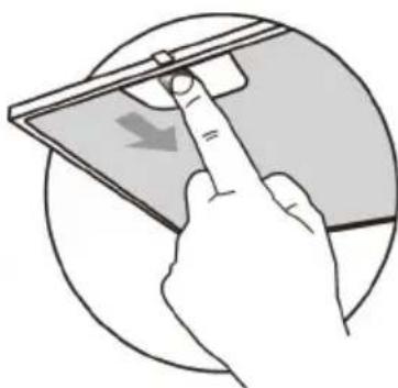
● Pull the comfort panels to open them. - Remove the filters one by one pushing them towards the back side of the hood unit and simultaneously pulling downwards.
- Any kind of bending of the filters has to be avoided when washing them. Before fitting them again into the hood make sure that they are completely dry. (The color of the filter surface may change throughout the time but this has no influence to the filter efficiency).
- When fitting the filters into the hood pay attention that they are mounted in correct position the handle facing outwards.
- Close the comfort panel.
natural_image
Hand holding a tablet device with a scroll, showing a downward arrow (no text or symbols)ACTIVATED CHARCOAL FILTER (RECIRCULATION VERSION)
REPLACING THE ACTIVATED CHARCOAL FILTER
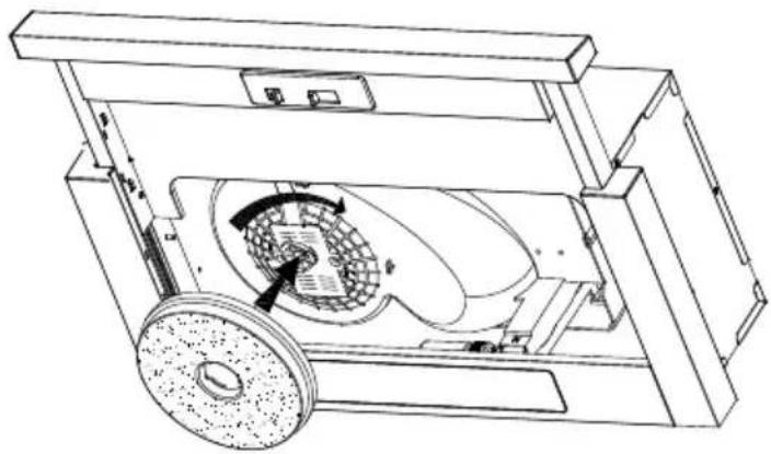
These filters are not washable and cannot be regenerated, and must be replaced approximately every 4 months of operation, or more frequently with heavy usage.
- Remove the metal grease filters
- Remove the saturated activated charcoal filter.
● Fit the new filters. - Replace the metal grease filters.
natural_image
Technical line drawing of a mechanical device with internal components and directional arrows (no text or symbols)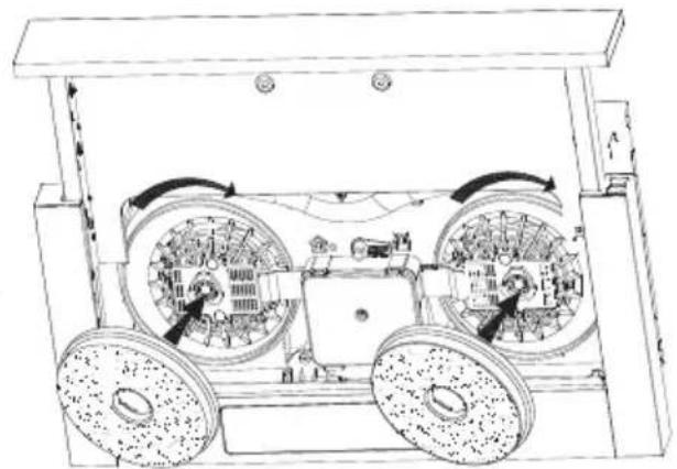
natural_image
Technical line drawing of a vehicle chassis with wheels and wheel rim (no text or symbols)
,QIRUP DWLRQ
When activated carbon filter attached, the suction power will be lowered.
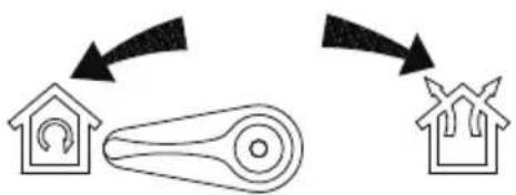
flowchart
graph TD
    A["House with gear icon"] --> B["Gear mechanism"]
    B --> C["House with gear icon"]
Venting knob position
| Extraction-air mode:Turn the venting knob heremeans venting outside | |
| Circulating-air mode:Turn the venting knob heremeans recirculation |
LIGHT REPLACEMENT
- When changing the light bulbs, the contacts are live.
- Before changing the light bulbs(s), unplug the appliance from the mains or switch off the circuit breaker in the fuse box.
1. Remove the grease filter.
natural_image
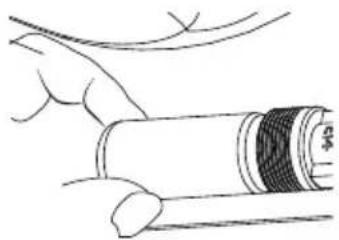
Technical line drawing of a mechanical assembly with internal components (no text or symbols)2. You can remove the lamp by rotating the lamp, the replacement of the lamp specifications refer to the table below.
| Max Power Voltage Picture Lamp Cap ILCOS D code | |||||
| LED module | 3W 220-240V | E14 | DBL-3-H-E14-35 | ||
natural_image
Illustration of a hand holding a cylindrical object with a bandage, no text or symbols presentDISPOSAL OF OLD ELECTRICAL APPLIANCES
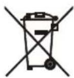

The European directive 2012/19/EU on Waste Electrical and Electronic Equipment (WEEE), requires that old household electrical appliances must not be disposed of in the normal unsorted municipal waste stream. Old appliances must be collected separately in order to optimize the recovery and recycling of the materials they contain, and reduce the impact on human health and the environment.
The crossed out "wheeled bin" symbol on the product reminds you of your obligation, that when you dispose of the appliance, it must be separately collected.
Consumers should contact their local authority or retailer for information concerning the correct disposal of their old appliance.
| Fault | Cause | Solution |
| Light on, but motor does not work | The blades are blocked. | |
| The capacitor is damaged. | Replace capacitor. | |
| The motor is damaged. | Replace motor. | |
| The internal wiring of motor is cut off/disconnected. An unpleasant smell may be produced. | Replace motor. | |
| Both light and motor do not work | Apart from the above mentioned, check the following: | |
| Light damaged. | Replace lights. | |
| Power cord loose. | Connect the wires as per the electric diagram. | |
| Oil leakage | Outlet and the air ventilation entrance are not tightly sealed. | Take down the outlet and seal with glue. |
| Leakage from the connection of U-shaped section and cover. | Take U-shaped section down and seal with soap or paint. | |
| Vibration | The blade, if damaged, can cause vibrating. | Replace the blade. |
| The motor is not tightly fastened. | Fasten the motor tightly. | |
| The cooker hood is not tightly fixed. | Fixed the cooker hood tightly. | |
| Insufficient suction | The distance between the cooker hood and the cooker top is too large. | Readjust the distance. |
| Too much ventilation from open doors or windows. | Choose a new place to install the appliance or close some doors / windows. | |
| The machine inclines | The fixing screws are not tight enough. | Tighten the fixing screw and make it horizontal. |
| The hanging screws are not tight enough | Tighten the hanging screw and make it horizontal. | |
- INSTALLATION
- USE
- MAINTENANCE
- METHOD 1
- Information
- METHOD 2
- Right Wrong
- CONNECTIONS
- DUCTED VERSION AIR EXHAUST SYSTEM
- Operation
- Switching on/off
- Motor Operation
- Light Operation
- CHECK VALVE INSTALLATION
- GREASE FILTERS
- ACTIVATED CHARCOAL FILTER (RECIRCULATION VERSION)
- ,QIRUP DWLRQ
- LIGHT REPLACEMENT
- Remove the grease filter.
- You can remove the lamp by rotating the lamp, the replacement of the lamp specifications refer to the table below.
- DISPOSAL OF OLD ELECTRICAL APPLIANCES
Brand : MIDEA
Model : MHS60S
Category : Range hood