
KF-875 - Measurement Megger - Free user manual and instructions
Find the device manual for free KF-875 Megger in PDF.


| Product Type | Digital Insulation Resistance Tester (Megohmmeter) |
| Brand | Megger |
| Model | KF-875 |
| Category | Measurement |
| Dimensions | 280 x 120 x 60 mm |
| Weight | 1.2 kg |
| Power Supply | 8 x AA batteries (included) or optional rechargeable battery pack |
| Insulation Resistance Ranges | Up to 2000 MΩ |
| Test Voltages | 100V, 250V, 500V, 1000V selectable |
| Voltage Measurement | AC/DC up to 600V |
| Continuity Test | Yes, with audible buzzer |
| Display | Large backlit LCD with bar graph |
| Safety Category | CAT IV 600V |
| IP Rating | IP54 (dust and splash resistant) |
| Data Storage | Up to 1000 readings with time stamp |
| Communication | USB and Bluetooth (optional) |
| Auto-Ranging | Yes |
| Auto-Off | Yes, programmable |
| Operating Temperature | -10°C to 50°C |
| Standards | IEC 61010-1, IEC 61557 |
| Accessories Included | Test leads, alligator clips, carrying case, batteries, user manual |
| Cleaning | Wipe with a soft damp cloth; do not use solvents |
| Calibration | Recommended annually |
| Reparability | Service by authorized Megger centers only |
Frequently Asked Questions - KF-875 Megger
User questions about KF-875 Megger
0 question about this device. Answer the ones you know or ask your own.
Ask a new question about this device
Download the instructions for your Measurement in PDF format for free! Find your manual KF-875 - Megger and take your electronic device back in hand. On this page are published all the documents necessary for the use of your device. KF-875 by Megger.
USER MANUAL KF-875 Megger
natural_image
Laboratory instrument with red and black components, labeled 'MEGGER' KF 975 (no visible text or symbols on device body)Contents
Chapter 1 Introduction----5
1.1 Instrument Description---- 5
1.2 Principle of Measurement---- 6
1.3 Instrument Connections----7
Chapter 2 Safety Information----8
2.1 General Safety Points----8
2.2 Electrical Safety----8
2.3 Solvent and Chemical Safety---- 8
2.4 Recycling and Disposal 8
Chapter 3 Instrument Setup 9
3.1 Receiving a Megger KF-875----9
3.1.1 Packaging----9
3.1.2 Checks----9
3.1.3 Location----9
3.2 Connecting the Power Supply---- 9
3.3 Setting Up the Glassware---- 10
3.3.1 Glassware Assembly---- 10
3.3.2 Connecting to the Megger KF-875---- 10
3.3.3 Filling and Changing Reagents---- 11
3.4 Loading the Printer---- 13
3.5 Connecting a USB Device---- 14
Chapter 4 Basics of Operation----15
4.1 Switching ON and OFF---- 15
4.2 Setting the Date and Time---- 15
4.3 Preconditioning---- 16
Chapter 5 Running a Test 17
5.1 Example Applications---- 17
5.2 Water Standard Test---- 17
5.3 How to Run a Test---- 17
5.4 Drift Rate Compensation---- 18
5.5 Overtitration----19
Chapter 6 Results----20
6.1 Printout Explanation---- 20
Chapter 7 Maintenance----21
7.1 Reagent Life 21
7.2 Cleaning the Glassware---- 21
Chapter 8 Technical Specifications----23
Chapter 9 Parts List 24
Chapter 10 Troubleshooting 25
Chapter 11 Conformity and Warranty 26
11.1 Declaration of Conformity---- 26
11.2 Quality Control---- 26
11.3 Customer Support and Service---- 26
11.4 Warranty----27
11.5 Warranty Exemptions----27
Chapter 1 Introduction
1.1 Instrument Description
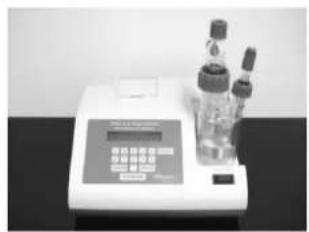
The KF-875 model has a small footprint, is easy to use, and supplied complete with a specifically designed low drift cell which is also suitable for outdoor use. The built-in battery and carry case, provide the versatility required by the laboratory and also the ease of use and portability required by the field engineer. Preprogrammed for typical transformer oil analysis calculation parameters (injection volume of 1.0ml and SG of 0.875)
Aquamax KF reagents have been specially formulated for use with KF-875 titrators. Reagent A (anode) is suitable for most routine applications and is especially useful for water content determination of oil samples, e.g. transformer oils, crude oils, etc. This anode reagent is supplied in “single shot” bottles of 100ml – No measuring of volumes required – No mixing of other solvents required. Reagent C (cathode) is supplied in “single shot” 5ml vials.
The carry case provides the portability required by the field engineer. The KF-875 can be transported, complete with glassware assembled, ready for immediate use on arrival at destination. Power cords, syringes, etc., can all be carried inside the carry case lid which has a special compartment for this purpose.
To obtain the full benefits that this instrument can offer it is recommended that you read this user manual before assembling the unit.
(All KF-875 power supplies are double insulated units that do not need an earth (ground) connection. These units are sealed and conform to CSA(LR84459), UL listings and CE requirements. KF-875 titrators only require a low voltage 15V input to the electronic / control circuitry. The moulded plastic casing of the instrument also provides additional insulation.)

natural_image
Laboratory instrument with red and metallic components, no visible text or symbols on the device itself1.2 Principle of Measurement
Karl Fischer titration is simply a means to measure water content of samples. Modern instruments, such as the Megger KF-875, use the Coulometric principle, whereby the water present in the sample is coulometrically titrated to a predefined end point at which there is a minute excess of free iodine present. Stoichiometrically, 1 mole of water will react with 1 mole of iodine, so that 1 milligram of water is equivalent to 10·71 coulombs of electricity. Combining the Coulometric technique with Karl Fischer titration, Megger KF Titrators determine the water content of the sample by measuring the amount of electrolysis current necessary to produce the required iodine. This is an absolute technique which does not require calibration of the reagents.

chemical
Chemical reaction equations showing sulfonation and hydrolysis of a diazo compound to form isocyanate and methyl sulfonateUsing the latest pulse current technology and our patented "ACE" control system, (Patent No.GB2370641), the Megger KF-875 automatically selects the appropriate titration speed dependent upon the amount of water present in the sample. The titration speed is reduced as the end point is approached, and when the titration is completed the instrument prints out and displays the results.
SCHEMATIC OF TYPICAL TITRATION

line
| Time | Electrolysis Current | Detector Signal | |------|----------------------|-----------------| | START | 0 | 0 | | END | 1 | 1 |1.3 Instrument Connections
Various ports are located on the back plate of the instrument. Below is a list of ports that can be found:
(1) Power Supply Port
The power supply port is for connecting to an 18V mains power supply, using the supplied power adaptor.
(2) RS232 Port
For updating Titrator software, connecting to other equipment for remote controlling (software specific protocols to be provided).
(3) USB/A Port
For exporting results data to a Removable Flash Drive (memory stick), when running sample tests in the field or remote locations, and subsequent transfer to PC at a later date for loading onto Results Manager files.
(4) USB/B Port
For connecting directly to PC to export data to Results Manager and enable results to be saved on files for future reference. (See Results Manager User Manual section).
Chapter 2 Safety Information
2.1 General Safety Points

This product is in conformity with the EU Directives 2004/108/EC and 2006/95/EC. This is based upon the compliance of the products with the harmonised standards: BS EN 61000-6-1:2007; BS EN 61010-2-030:2010; and BS EN 61326-1:2013.

This product is manufactured in accordance to RoHS following the EU Directive 2011/65/EU; it does not contain any of the restricted substances in concentrations and applications banned by this directive.
2.2 Electrical Safety

The Megger KF-875 Moisture Meter complies with the international standard IEC 61010. Only operate this instrument within the mains voltage supply that is specified on the back of the instrument, an incorrect mains supply can damage the instrument. Never open the housing of the instrument, only GR Scientific personnel who are trained to service the instrument can open the housing. There is risk of electrocution if live components are touched.
Always ensure the instrument is disconnected from the mains power supply when connecting or disconnecting cables from the back of the instrument, as electrostatic discharge can build up.
2.3 Solvent and Chemical Safety

When using flammable or irritant solvents and chemicals, follow suitable safety measures to protect yourself and others around. Always use the instrument in a well ventilated area, clean up spilled fluids immediately, and keep flame sources away from the work area. Always follow the safety instructions of the chemical manufacturer and apply the correct countermeasures that are required.
2.4 Recycling and Disposal

This instrument is covered by the WEEE (Waste Electronic and Electrical Equipment) Directive 2012/19/EU to prevent the negative and harmful effects on the environment and public health. For more information on how to dispose of the instrument safely, please contact your local authority, your local waste disposal company or Megger directly.
Chapter 3 Instrument Set Up
3.1 Receiving a Megger KF-875
3.1.1 Packaging
The Megger KF-875 is packaged in suitable protective packaging to ensure that no damage occurs during transit, only this packaging is suitable for the safe transportation during transit. Please keep this packaging as transit of the instrument may need to occur in the future.
3.1.2 Checks
Once you have received the instrument, immediately check to make sure that there is no damage and no parts are missing. A delivery note will be included within the package to use to compare with the shipment.
Ensure that inside the shipment has a calibration certificate for the instrument, if not please request this from the manufacturer.
3.1.3 Location
Locate the instrument within the work area where it is free from excessive:
- vibrations
- direct sunlight
- contamination from chemicals
- explosive environments
- corrosive atmospheres
- major temperature fluctuations
3.2 Connecting the Power Supply
The Megger KF-875 is powered by an external mains source, with a power pack to ensure this connection is the correct voltage of 18V DC for the instrument. Damage may occur beyond repair and the user may be subjected to electric static shocks if the incorrect power is supplied.
Note: Refer to Chapter 2 for more safety information.

To avoid risk of electrocution, make sure the I/O switch is set to OFF before connecting the power supply.
3.3 Setting Up the Glassware
3.3.1 Glassware Assembly


natural_image
Clear glass laboratory gas collection bottle with red capets and tubing (no visible text or labels)3.3.2 Connecting to the Megger-KF 875 Moisture Meter

(1) Position the titration vessel on the Titrator.

natural_image
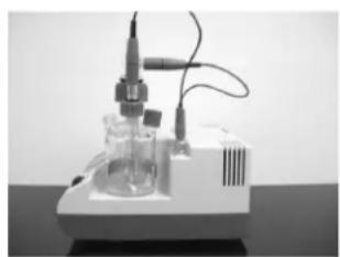
Three medical or laboratory glassware items on a dark surface, no visible text or symbols(2) Position the electrodes on the titration vessel and tighten by hand.
Note: The glass joints do not require PTFE sleeves or grease. The special screw fittings seal the vessel from the atmosphere and are easily released, even after several weeks.
natural_image
Laboratory equipment with digital display and two laboratory glassware on a dark surface (no visible text or symbols)
natural_image
Hand holding a laboratory glassware device on a digital display stand (no visible text or symbols)(4) Place the stirrer bar inside the titration vessel.
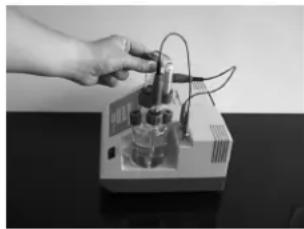
(3) Connect the generator and detector leads to the vessel and then to the BNCs.

natural_image
Close-up of a gloved hand using a laboratory instrument with glassware and test tubes (no visible text or symbols)t
natural_image
Laboratory setup with a glassware and test tube mounted on a base, no visible text or symbols(5) Fit injection septas into the injection port caps and screw tightly by hand onto the injection ports.
(6) Position the drying tube with desiccant and tighten by hand.
natural_image
Hand operating a laboratory instrument with wires and components (no visible text or symbols)The assembled titration cell is now ready to be charged with reagents prior to use. Please be sure to assemble correctly every time the cell is cleaned or re-filled. It is recommended that the Titrator is NOT switched on until after the titration vessel has been charged with reagents. This will avoid damage being caused to the electrodes by the stirrer bar. Avoid twisting the electrode leads otherwise they may become damaged.
3.3.3 Filling and Changing Reagents
Megger KF-875 Titrators have been designed to operate with all major Coulometric Karl Fischer reagents. For most routine applications generator electrodes with frit/diaphragm are used in conjunction with 100ml of anode reagent and 5ml of cathode reagent. We strongly recommend using Aquamax KF A and C Reagents as these have been specially formulated for oil samples.
When analysing Transformer oils, Crude oils and other petroleum products, there are specially formulated anode reagents which contain other solvents to improve sample miscibility and solubility are recommended. There are also single Coulometric reagents available for use with fritless generator electrodes. Although we do not recommend these for oil sample analysis.
Note: When analysing samples of Ketones, amines or others which may interfere with the reaction it is advisable to use specialised reagents which can be obtained from various suppliers.
Although reagents can be poured into the titration vessel whilst it is located on the Titrator, we recommend that the vessel, electrodes and electrode leads are removed from the instrument whilst this procedure is performed to avoid reagent spillage onto the instrument casing.
Note: Any spillage onto the instrument casing should be wiped off immediately to avoid damage or staining.

natural_image
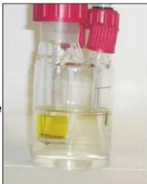
Hand in blue glove holding a small object over a glass flask containing red liquid (no text or symbols visible)Remove the drying tube and injection septa. Using the funnel supplied, charge the titration vessel with 100ml anode reagent (this is approximately to the bottom line on the vessel).

natural_image
Hand in blue glove pouring liquid into a glass vial with red and yellow components (no text or symbols visible)Also using the funnel, charge the inner chamber of the generator electrode with 5ml of cathode reagent. (This is not required if using fritless generator electrode).
Note: It is not necessary to clean the funnel between reagents.
Reconnect the drying tube and injection septa so that the titration vessel is sealed from ingress of atmospheric moisture.
Locate the complete titration vessel onto the Titrator and connect the electrode leads onto the appropriate sockets
There are some bi-products formed in the cathode chamber which can react with the iodine in the anode chamber and this can cause longer preconditioning times. It is advisable to have the cathode reagent 2-3mm lower than the anode reagent when first charging the titration vessel to speed up preconditioning.
natural_image
Transparent plastic bottle with red and yellow liquid, no visible text or symbolsThe Megger-875 Titrator is now ready to be switched on.
3.4 Loading the Printer
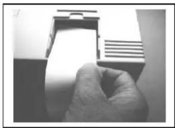
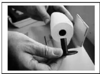
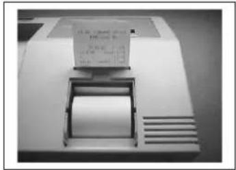
To load the paper into the printer, first open the paper roll holder lid above the print head and remove the old roll and rollers. Now fit rollers to new paper roll, load as shown and insert the paper into the slot at the rear of the print head. As soon as the printer sees the paper it will automatically load it. To avoid damage to the printer mechanism it is advisable to only use the correct part number thermal paper rolls.

natural_image
Close-up of a white electronic device with ventilation grilles and a handle, no visible text or symbolsCut the end of the paper roll at a slight angle as shown. This will make it easier to feed into the printer mechanism.
natural_image
Close-up of a hand holding a small electronic device component (no visible text or symbols)The mechanism has optical sensors which detect the paper and will auto feed.

Schematic of paper feed.
natural_image
Close-up of hands holding a rolled document with a metal clip, no visible text or symbolsFit the paper bobbin onto both sides of paper roll.

natural_image
Close-up of a hand holding a rolled document or scroll, with no visible text or symbols.Locate paper roll into the compartment.
3.5 Connecting a USB Device
To use the memory store, insert Flash Drive into USB port A, the Titrator will see it and a symbol will appear on the display.
The symbol will appear blacked out while the drive is being written to and then clear when idle.
The drive should only be removed when in the idle mode.
To read data saved on the drive insert it into a PC USB port. Start Results Manager, load selected file and then save in the format you require. Refer to Chapter 7 Results Manager.
Chapter 4 Basics of Operation
4.1 Switching ON and OFF
The Megger KF-875 Moisture Meter has one I/O switch and is powered by either a mains power supply using an adaptor, or a built-in battery for power.
Note: Refer to Chapter 3.2 for power supply connections.

To avoid risk of electrocution, make sure the I/O switch is set to OFF before connecting the power supply from a mains source.
4.2 Setting the Date and Time
(1) Switch on the Megger KF-875 and wait for it to display the following:
Megger KF-875
v2.6n
Press START
(2) Hold down the [START] key until the Megger KF-875 displays:
Set Date/Time:
DD/MM/YYYY
HH:MM:SS
(3) Use the [ . ] move the cursor across the screen.
(4) Use the numerical keys to set / alter the required number.
(5) When completed press the [ENTER] to save the changes and exit.
4.3 Preconditioning
(1) Assemble glassware (see Assembly Instructions)
(2) Charge vessel and generator electrode with reagents (see Filling & Changing Reagents)
(3) Locate assembled titration vessel onto the Megger KF-875
(4) Connect the electrode leads
(5) Connect mains lead / power cord
(6) Switch ON (using switch on rear panel) and wait for display to show:

Note: If required adjust the stirrer speed using the arrow keys on the front of the instrument.
(1) Press [START] and allow the instrument to precondition (equilibrate).

At the end of the precondition period the display will show:

After the initial drift has been calculated, in micrograms of water per minute, the Megger KF-875 is ready for operation.
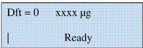
The background drift value will usually slowly decrease with time as the titration vessel becomes drier and more stable. Although it is possible for the Titrator to be used at high drift values, it is advisable to wait until the drift value is below 20 g/minute, and stable, before commencing, especially for low water content samples in the ppm ranges.
The lower and more stable the drift - the more accurate the result.
Chapter 5 Running a Test
5.1 Example Applications
Transformer/Insulating Oils
(ASTM D 1533, BS EN 60814, IEC 60814)
Due to the viscosity of these samples, and the fact that typical water content levels are in the range 5 – 40 ppm, it is usually necessary to inject sample volumes of 1 ml. This means that up to 50 samples would fill the titration cell. Provided that the other criteria governing reagent life, (total water titrated and reagent age), have not been reached, then it is possible to switch off the Titrator and allow the oil to separate from the reagent. The oil can then be siphoned off and the instrument switched on again. After this operation it may take up to 30 minutes before the instrument settles down to a stable baseline. If it takes longer than 30 minutes then it is advisable to clean the cell and recharge with fresh reagents.
5.2 Water Standard Test
In principle, standardization of a Megger KF-875 is not necessary since the water titrated is a direct function of the coulombs of electricity consumed. However it is recognised that reagent performance can deteriorate with use over time and it is recommended that the Titrator is regularly monitored by introducing a known quantity of water that is representative of the typical range of water concentrations being determined in samples. Several of the ASTM methods for water content of crude oil and petroleum products suggest injecting between 1.0 l and 10 l distilled water to check reagent performance.
Each of these methods requires that the result be recorded in micrograms of water, not as a calculated ppm or percentage.
5.3 How to Run a Test
Example: Transformer oil sample by V/SG
Result Format = mg/kg
Calculation Mode = V/SG
Sample Volume = 1.0 ml
Sample SG = 0.875
ANALYSIS METHOD
(1) Confirm that KF-875 is in Ready mode.
(2) Flush 1.0ml syringe several times (minimum 6 times) with sample.
(3) Fit luer needle and flush through with sample.
(4) Draw sample into syringe beyond the 1.0ml marking.
(5) Invert syringe so that any air bubbles can be ejected through the needle and adjust syringe plunger to the 1.0 ml mark.
(6) Wipe off excess sample from outside of needle using a clean, dry tissue or paper towel.
(7) Pierce needle through injection septa of titration vessel (1 - 2 cm).
(8) Press START.
(9) Push needle into anode reagent and inject sample.
(10) Withdraw needle from titration vessel.
(11) Read result, in mg/kg (ppm) water, on display and printout.
(12) Repeat steps 2 - 11 if duplicate result required.
5.4 Drift Rate Compensation
At the start of any titration, the drift value in the top left corner of the screen (in micrograms per minute), is stored in memory. This ensures that the displayed result is corrected for any ingress of atmospheric moisture during the titration period.
Whilst in the Ready condition, the Megger KF-875 continually compensates for any drift caused by atmospheric moisture ingress or reagent decomposition and displays this information, which is updated every 10 seconds. If the drift value is above 30 g /minute the display will show “Drift Warning START to continue.” This is a warning that the value is high, however the instrument can still be used by simply pressing [START] to continue.
Drift Warning
START to continue
Provided the drift rate is stable then it usually acceptable to continue operation. The Aquamax titration cell design can provide drift values down to less than 5 g /minute but can also operate at much higher values. The maximum drift value is 60 g /minute but we recommend operating up to a maximum of 25 whenever possible.
If the drift value is above 60 g per minute the display will read:
"EXCESS DRIFT - SEE INSTRUCTION MANUAL"
Most common causes of excess drift are:
– Titration vessel not properly sealed (check septa & fittings)
- Reagents almost depleted (clean & recharge the cell)
– Sample introduced before pressing [START] key
- Trace moisture on cell walls
If excess drift occurs, switch the instrument off, remove titration cell from clamp, gently swirl the anode reagent around the cell walls, replace cell in clamp, switch instrument on and allow to precondition.
5.5 Overtitration
If the detector electrode senses too much lodine in the titration cell, usually caused by instrument being left unoperated for a long period, the display will read :-
"OVERTITRATION - SEE INSTRUCTION MANUAL"
Simply add 3 - 5 microlitres of water, or a small amount of a known wet sample, until the detector signal bars on bottom left of display are activated. Then the instrument will automatically carry out its precondition.
Chapter 6 Results
6.1 Printout Explanation
The KF875 prints the calculated results in ppm (mg/Kg) along with time and date of the titration and run number. The KF875 automatically increments the next run number every time you press the start button. The run counter is reset to zero when power is switched off and back on again. A duplicate set of results can be printed out simply by holding down the Start button for 3 seconds. Results memory is cleared after duplicate print out or when power is switched off.
Print Out Example
Megger KF 875
V xxxx
Serial No. 71000
Calibrated DD/MM/YYYY
Run Date
Run: 1 Run Time F
Nett Count 0.0 g
Drift 00
Result Format mg/kg
Calculation Mode V/SG
Volume 1.0000 ml
Density 0.8750
Res: 0.0 mg/kg
Run: 2 Run Time F
Nett Count 0.0 μg
Drift 00
- Titrator model
- Software version
- Titrator serial number
- Date Titrator calibrated
- Date sample run
- Run no. and time of analysis (F = generator with frit)
- Nett microgram count (after drift correction)
- Drift value at start of titration
– Result format selected - Calculation mode selected
- Sample volume
- Sample density
– Calculated result water content - Subsequent runs of the same sample and calculation parameters show run number, run time, nett count.
- Drift value.
Chapter 7 Maintenance
7.1 Reagent Life
There are three main factors which govern the life of Coulometric reagents, and therefore, the frequency of cleaning and recharging the titration cell:
(1) The physical size of the titration cell allows for 50 – 60mL of sample to be added. For the analysis of most liquid samples (e.g. solvents) Megger KF-875 Titrators normally only requires a few micro litres to be injected, therefore the maximum volume of 50 – 60mL should not become a limiting factor. (Oil samples are an exception and are dealt with elsewhere in this manual).
(2) The total amount of water that can be analysed before saturation of the reagents varies slightly from one reagent manufacturer to another. Typically a 100 ml charge of Anode reagent will analyse up to 1 gm water, whilst a 5 ml charge of Cathode reagent will analyse up to 250 mg water. Considering that the injected sample volume is normally small, and also that the analysis is usually for the determination of low levels of water, these water capacity values are not normally a limiting factor.
(3) Similar to all other Karl Fischer reagents, Coulometric reagents will deteriorate when exposed to sunlight and with increases in temperature. Placing the instrument in direct sunlight or near to a heat duct can decrease the reagent life. As reagents age, the titration speed will reduce and the drift value will increase.
7.2 Cleaning the Glassware

IMPORTANT
The platinum mesh and wires of the electrodes are fragile and can be easily bent or broken. Extreme care MUST be taken when disassembling, cleaning and reassembling the titration cell. The generator electrode is the most expensive part of the KF glassware.
DO NOT USE BRUSH TO CLEAN INSIDE ELECTRODE AS THIS COULD DAMAGE CONNECTIONS.
Coulometric reagents are flammable and toxic, so care should always be taken when handling them and when cleaning the glassware. Whenever possible this should be done in a safe area, e.g. inside a fume cupboard. Reagents should not be recharged while the titration cell is still attached to the Titrator.
Under normal circumstances the titration cell can be used for a large number of samples before having to replenish the reagents. The glassware only requires simple cleaning procedure, normally just rinsing with solvent, drying and then re-charging with fresh reagent. Once the reagents have been exhausted, or when the titration cell maximum volume has been reached, it should simply be necessary to:
(1) DISASSEMBLE titration cell (disconnect leads from Titrator).
(2) EMPTY the titration cell and generator electrode.
(3) RINSE all parts with methanol. Do not use brush on electrodes.
(4) DRY all parts.
(5) REASSEMBLE glassware.
(6) RECHARGE with fresh reagents.
If the cell is heavily contaminated then it may be necessary to clean it more thoroughly. For oil samples, cleaning with chloroform or xylene is suggested, whilst for salt deposits a water wash may be required. Use whichever solvent is most suited for the sample type. The titration vessel can even be cleaned with hot soapy water and a bottle-brush.
However, after cleaning with suitable solvent, all glassware parts, MUST be rinsed inside and out with methanol.
They can then be dried with a warm air blower, such as a domestic hair dryer, placed in a low temperature oven at 40 – 50 °C, or left in a desiccator.
After being fully dried, reassemble the titration cell and charge with fresh reagents.
THE MORE THOROUGHLY THAT THE TITRATION CELL IS CLEANED AND DRIED, THE FASTER THE INSTRUMENT WILL STABILISE READY FOR OPERATION AFTER RECHARGING REAGENTS.
Under normal conditions, the Megger KF-875 should be ready for operation within 5 – 10 minutes after reassembly, however it could take considerably longer before to completely stabilise if the drying procedure has not been properly carried out.
GENERATOR ELECTRODE - ACID WASH PROCEDURE
If the frit of the generator electrode has become blocked or severely stained with samples such as crude oils, then it may occasionally be necessary to use an acid wash procedure.
(1) Rinse the empty generator electrode with Xylene or other suitable solvent.
(2) Place the electrode in a 250ml conical flask, ensure the electrode is suspended and not resting on the platinum mesh. Add 10ml Xylene to the inner cathode chamber and leave to stand for 10 minutes. Remove the Xylene.
(3) Repeat using 10ml of Methanol then gently swirl to remove residual solvent and remove.
(4) Add 10ml deionised water to inner cathode chamber and allow to stand for 30 minutes.
(5) Remove any remaining water, add 10ml 50/50 HCL and allow to stand for 1 hour. Top up any loss of HCL through the frit. After 1 hour carefully pour the acid into a flowing water stream in the sink, ensuring that the breather hole midway down the side of the electrode is positioned at the top when pouring acid out.
(6) Thoroughly rinse the electrode using a wash bottle containing deionised water. Add 10ml deionised water to the inner chamber and allow to stand for 30 minutes.
(7) Remove any remaining water, add 10ml Methanol and allow to stand for 10 minutes. Ensure that the outer surfaces of the electrode do not come in contact with waste solution gathering in the bottom of the vessel.
(8) Drain remaining solvent from inner chamber and dry electrode.
Note: Wear safety goggles and protective gloves when handling acid.
Chapter 8 Technical Specifications
Electrolysis Control: Patented "ACE" Control System GB2370641
End Point Detection: AC Polarisation
End Point Indication: Visual Display/Print Out/Acoustic Beep
Titration Vessel: Low Drift Cell Design, no grease or PTFE sleeves required
Measuring Range: Possible 1μg – 200mg Water Typical 1μg – 10mg Water
Moisture Range: 1ppm – 100% Water
Max. Sensitivity: 0.1μg
Max. Titration Speed: 2.24mg per minute
Max. Current: 400ma
Drift Compensation: Automatically Controlled
Precision: 10-100μg ± 3μg, 100μg -1mg ± 3μg, above 1mg ± 0.3%
Start Delay Time: 0-30 minutes, user selectable
End Delay Time: 0-30 minutes, user selectable
Calculation Modes: Weight/weight (W/w) Weight/Dilution Ratio (W/K) Volume/Density (V/SG) Volume/volume (V/v) (User Programmable)
Display Format: g, mg/kg, ppm, %
Print Format: g, mg/kg, ppm, %
Statistics: Max, Mean, Min values up to 99 runs
Method Storage: 10 User Programmable Methods
Sample ID Number: User Programmable
Stirrer Speed: Microprocessor Controlled – User Selectable
Languages: Multi Languages – User Selectable
Calendar/Clock: Analysis Time & Date Print Out
Data Outputs: USB & RS232 Ports
Removable Data Storage: Flash Drive (memory stick)
Data Entry: 18 Key Touchpad
Display: 40 Character Alphanumeric Backlit LCD
Printer: 42 Character High Speed Thermal Printer
Power Supply: 90-264V AC, 47-63Hz
Battery Life: 8 Hours Running Time from Fully Charged
Unit Dimensions: 250 x 245 x 120 mm
Weight: 3kg
Chapter 9 Parts List
Part No: 6111-636
All the following parts are included as standard, but can also be purchased as single items.
18V Power Adaptor
In-Car Adaptor
Glassware Set LDC Twin Port
Comprises of:
Desiccant Tube LDC & Cap
Pack Injection Septa (10 pack)
Molecular Sieve
Stirrer Bar
Polypropylene Funnel
Paper Roll (Thermal) Single
Luer Needle 19 Gauge (Screw Fit)
Gas Tight 1.0ml Syringe
Carry Case
Chapter 10 Troubleshooting
Overtitration
Detector senses too much lodine. Usually caused by old reagents or stirrer switched off. Check stirrer speed.
Add 3-5 micro litres of water until detector bars activate, and allow to precondition.
Excess Drift
Indicates excess moisture ingress or condensation on cell walls. Switch OFF. Remove titration cell from clamp and gently swirl anode reagent around the cell walls. Reconnect, switch ON, and allow to Precondition.
Long Preconditioning Time
Normally caused by glassware not being sufficiently dried before assembly. Re-clean glassware and electrodes, dry thoroughly and charge with fresh reagents.
Progressively Lower Results for Same Sample
Moisture contamination of syringe. Flush syringe and needle with sample several times before beginning new test.
Poor Repeatability for Same Sample
Sample size probably too small or moisture contamination of syringe. Increase sample size and flush syringe and needle several times before beginning new test.
Warning Letters on Print Out
Warning letters will be printed after time of each analysis to signify the following:
U – Uncalibrated
E – Calibration expired
B – Battery level low
A - ACE system active
Note: The software version is displayed on the Titrator immediately after the unit is switched on.
Chapter 11 Conformity and Warranty
11.1 Declaration of Conformity

This Megger product are in conformity with the EU Directives:
• 2004/108/EC Electromagnetic Compatibility Directive
• 2006/95/EC Low Voltage Directive
This is based upon the compliance of the products with the harmonised standards:
- BS EN 61000-6-1:2007 Electromagnetic Compatibility. Generic immunity standard. Residential, commercial and light industry;
- BS EN 61010-2-030:2010 Safety requirements for electrical equipment for measurement, control and laboratory use. Particular requirements for testing and measuring circuits;
- BS EN 61326-1:2013 Electrical equipment for measurement, control and laboratory use. EMC requirements. General requirements.
11.2 Quality Control
The Megger KF-875 is adequately and professionally Quality Controlled to ensure that it is fully functional and to ensure that it meets all of the requirements that the instrument supports.
11.3 Customer Support and Service
For service requirements for Megger Instruments contact:
Megger Limited or Megger
Archcliffe Road Valley Forge Corporate Centre
Dover 2621 Van Buren Avenue
Kent CT17 9EN Norristown PA 19403
UK. USA.
Tel: +44 1304 502 243 Tel: +1 610 676 8579
Fax: +44 1304 207 342 Fax: +1 610 676 8625
Megger operate fully traceable calibration and repair facilities, ensuring your instrument continues to provide the high standard of performance and workmanship you expect. These facilities are complemented by a worldwide network of approved repair and calibration companies to offer excellent in-service care for your Megger products.
When an instrument requires recalibration, or in the event of a repair being necessary, a Returns Authorisation (RA) number must first be obtained from one of the addresses above.
You will be asked to provide the following information to enable the Service Department to prepare in advance the receipt of your instrument, and to provide the best possible service for you.
- Model, e.g. S1-554
- Serial number, to be found on the rear of the instrument or on the calibration certificate.
- Reason for return, e.g. Calibration required or repair.
-
Details of the fault if the instrument is to be repaired.
-
Make a note of the RA number. A returns label can be emailed or faxed to you.
-
Pack the instrument carefully to prevent damage in transit.
-
Ensure the returns label is attached, or that the RA number is clearly marked on the outside of the package and on any correspondence, before sending the instrument, freight paid, to Megger. Copies of the original purchase invoice and packing note should be sent simultaneously by airmail to expedite clearance through customs. In the case of instruments requiring repair outside the warranty period, an immediate quotation can be provided when obtaining the RA number.
-
You may track the progress of your return on line at www.megger.com.
Approved Service Centres
A list of Approved Service Centres may be obtained from the UK address above, or from the Megger website www.megger.com.
11.4 Warranty
Under the conditions of our warranty, all faults which are proved to be due to material, construction or manufacturing defects, which occur within 12 months of the delivery date, will be repaired or replaced, (at our discretion), free of charge at our premises. Freight costs will be chargeable along with any inspection work which was not necessitated by manufacturing or material defects. Breakages of glassware or electrodes are not covered by this guarantee. In the event of instrument failure during the warranty period, written authorisation must be obtained from the manufacturer prior to shipping. Any unauthorised prior repair or adjustments will automatically invalidate the warranty.
11.5 Warranty Exemptions
Some parts of the instrument and the accessories cannot be replaced under warranty. These include:
- Glass Vessels
- Syringes
- Electrodes
- Contents
- Chapter 1 Introduction----5
- Chapter 2 Safety Information----8
- Chapter 3 Instrument Setup 9
- Chapter 4 Basics of Operation----15
- Chapter 5 Running a Test 17
- Chapter 6 Results----20
- Chapter 7 Maintenance----21
- Chapter 8 Technical Specifications----23
- Chapter 9 Parts List 24
- Chapter 10 Troubleshooting 25
- Chapter 11 Conformity and Warranty 26
- Chapter 1 Introduction
- Instrument Description
- Principle of Measurement
- Instrument Connections
- Power Supply Port
- RS232 Port
- USB/A Port
- USB/B Port
- Chapter 2 Safety Information
- General Safety Points
- Electrical Safety
- Solvent and Chemical Safety
- Recycling and Disposal
- Chapter 3 Instrument Set Up
- Receiving a Megger KF-875
- Packaging
- Checks
- Location
- Connecting the Power Supply
- Setting Up the Glassware
- Glassware Assembly
- Connecting to the Megger-KF 875 Moisture Meter
- Filling and Changing Reagents
- Loading the Printer
- Connecting a USB Device
- Chapter 4 Basics of Operation
- Switching ON and OFF
- Setting the Date and Time
- Preconditioning
- Chapter 5 Running a Test
- Example Applications
- Transformer/Insulating Oils
- Water Standard Test
- How to Run a Test
- Example: Transformer oil sample by V/SG
- ANALYSIS METHOD
- Drift Rate Compensation
- Drift Warning
- START to continue
- Overtitration
- Chapter 6 Results
- Printout Explanation
- Print Out Example
- Chapter 7 Maintenance
- Reagent Life
- Cleaning the Glassware
- IMPORTANT
- DO NOT USE BRUSH TO CLEAN INSIDE ELECTRODE AS THIS COULD DAMAGE CONNECTIONS.
- THE MORE THOROUGHLY THAT THE TITRATION CELL IS CLEANED AND DRIED, THE FASTER THE INSTRUMENT WILL STABILISE READY FOR OPERATION AFTER RECHARGING REAGENTS.
- GENERATOR ELECTRODE - ACID WASH PROCEDURE
- Chapter 8 Technical Specifications
- Chapter 9 Parts List
- Chapter 10 Troubleshooting
- Overtitration
- Excess Drift
- Long Preconditioning Time
- Progressively Lower Results for Same Sample
- Poor Repeatability for Same Sample
- Warning Letters on Print Out
- Chapter 11 Conformity and Warranty
- Declaration of Conformity
- Quality Control
- Customer Support and Service
- Approved Service Centres
- Warranty
- Warranty Exemptions
Brand : Megger
Model : KF-875
Category : Measurement