
3166 - Measuring device Kyoritsu - Free user manual and instructions
Find the device manual for free 3166 Kyoritsu in PDF.


| Product Type | Digital Multimeter |
| Brand | Kyoritsu |
| Model | 3166 |
| Dimensions | 180 x 85 x 40 mm |
| Weight | 350 g (including battery) |
| Power Supply | 9V battery (6F22 or NEDA 1604) |
| AC Voltage Range | 0 to 600V |
| DC Voltage Range | 0 to 600V |
| AC Current Range | 0 to 10A |
| DC Current Range | 0 to 10A |
| Resistance Range | 0 to 40 MΩ |
| Capacitance Range | 0 to 100 µF |
| Frequency Measurement | Up to 1 MHz |
| Diode Test | Yes |
| Continuity Buzzer | Yes |
| Safety Rating | CAT III 600V, CAT II 1000V |
| Display | LCD, 6000 counts |
| Auto Range | Yes |
| Data Hold | Yes |
| Overload Protection | Yes |
| Maintenance and Cleaning | Wipe with dry cloth; avoid moisture and solvents |
| Spare Parts and Repairability | Replaceable battery and fuses; service by qualified technician |
Frequently Asked Questions - 3166 Kyoritsu
User questions about 3166 Kyoritsu
0 question about this device. Answer the ones you know or ask your own.
Ask a new question about this device
Download the instructions for your Measuring device in PDF format for free! Find your manual 3166 - Kyoritsu and take your electronic device back in hand. On this page are published all the documents necessary for the use of your device. 3166 by Kyoritsu.
USER MANUAL 3166 Kyoritsu
- This instruction manual contains warnings and safety rules that must be observed by the user to ensure safe operation of the instrument and retain it in safe condition. Therefore, read these operating instructions thoroughly and completely before using the instrument.
- The symbol on the instrument means that the user must refer to the relevant section of this instruction manual for safe operation of the instrument.
● Pay particular attention to all WARNINGS and CAUTIONS in this instruction manual. WARNING indicates warnings to avoid electrical shock and CAUTION indicates cautions to avoid damage to the instrument.
4-3 Insulation Resistance Measurement
⚠ WARNING
To avoid electrical shock, do not touch the test lead tips and the circuit under test during measurement.
CAUTION
To avoid damage to the instrument, insulation measurement must be performed on de-energized circuits only. Make sure that the circuits or equipment is disconnected before proceeding with an insulation test.
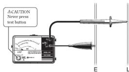
(1) Connect the test leads to the instrument and the circuit under test.

(2) Check the circuit under test is not energized as follows. Connect the test leads to the circuit under test and read a voltage value. If the circuit is live, the meter indicates the voltage. If the meter indicates 0V, the circuit is dead.
(3) Press test button. Read the red megaohm scale directly.
● Continuous Measurement
A lock down feature is incorporated on the test button. Pressing and turning it clockwise lock the test button in the continuous operating position.
- Always make sure to insert the plug of test leads fully into the terminal of the instrument
- Never exceed the maximum allowable input of any measuring range when making measurement.
- Make sure to never apply a voltage more than 600V AC or DC between the terminal of the instrument and earth.
- Never try to operate the instrument in an explosive atmosphere (i.e. in the presence of flammable gases or fumes, vapor or dust).
- Always inspect the instrument, test leads and accessories for any sign of damage or abnormality before every use. If abnormal conditions exist (e.g. broken test leads, cracked enclosure of the instrument), do not try to make measurements.
- Do not push the test button or lock it down while connecting test leads.
- Do not touch the circuit under test during insulation testing.
- Make sure to remove the test lead from the instrument and turn the power off before opening the battery compartment cover for battery replacement.
- Always turn the power off after use.
- Do not expose the instrument to the direct sun, dew fall, or extreme temperatures.
- Do not expose the instrument to a temperature of more than 50°C.
- Calibration and repair of any instrument should only be performed by qualified and trained service technicians.
- Do not install substitute parts or perform any unauthorized modification of the instrument. Return the instrument to your distributor for service and repair to ensure that safety features are maintained.
- The instrument must be used by a competent, trained person and operated in strict accordance with the instructions. KYORITSU will not accept liability for any damage or injury caused by misuse or noncompliance with the instructions or safety procedures. It is essential to read and understand the safety rules contained in the instructions. They must be observed when using the instrument.
2. Features
● AC voltage measurement can be made without depressing the test button.
● Battery check facility
● Uses only 4×1.5V battery type R6, AA or equivalent.
3. Specifications
● Measuring ranges accuracy(at 23±5°C, relative humidity 45-75%)
To release the lock turn the test button counter clockwise.
Never leave the test button locked down when not in use.
(4) Discharging capacitance of circuit under test. It is possible that capacitance has been stored in the circuit under test after insulation testing. To discharge the e circuit capacitance reverse the connection of the earth clip and line probe. Remaining electric charges can be observed on AC voltage warning range.
⚠ WARNING
Do not touch the circuit under test immediately after testing. Capacitance stored in the circuit may cause electric shock.
5. Battery Replacement
⚠ WARNING
To avoid shock hazard disconnect the test leads from the instrument.
To replace the batteries, first disconnect all test leads from the instrument. Open the battery compartment cover by unscrewing the metal captive screw to reveal battery compartment. The four 1.5V SUM-3(R6)type batteries are located in a compartment. Always replace all four batteries with new ones at the same time. Never mix old and new ones. Screw the battery compartment lid back on before using the instrument.
Fixing Screw

△CAUTION Install battery y in correct polarity as marked inside the case.
Insulation resistance ranges:
| MODEL 3165 MODEL 3166 | ||
| Test voltage | 500V 1000V | |
| Measuring range | 1000MΩ 2000MΩ | |
| Mid-scale value | 20MΩ 50MΩ | |
| Output voltage on open circuit | Rated test voltage +20% -0% | |
| Output short circuit current | 240μA max | 550μA max |
| Primary Effective Measuring Range | 1-500MΩ 2-1000MΩ | |
| Accuracy | ±5% of indicated value at primary effective measuring range±0.7% of scale length at 0 and ∞±10% of indicated value at other measuring range | |
AC Voltage Warning:
| Warning range 0-600V AC |
| Accuracy ± 3% of scale length |
Power supply 4×1.5V battery type SUM-3,R6,AA or equivalent Overload protection Insulation Resistance Ranges
Model 3165: 600V (DC+ACp-p) for 10 seconds Model 3166:1200V (DC+ACp-p) for 10 seconds AC Voltage Range
720V (DC+ACp-p) for 10 seconds
Operating temperature & humidity 0-40°C, relative humidity up to 85% Storage temperature & humidity -10-50°C, relative humidity up to 75% Withstand voltage 3700V AC for one minute between electrical
Insulation resistance More than 50MΩ at 1000V between electrical circuit and housing case Dimensions 90(L)×137(W)×40(D)mm Weight 330g Accessories Test leads Model 7025(1 set) Pouch for test leads (1 piece) Shoulder strap (1 piece) R6 batteries (4 pieces) Instruction manual (1 copy)
4. Operation
4-1 Preparation for testing
(1) Mechanical zero adjustment
Without pressing the Test button, check that the pointer lines up with
6. Notes on Housing Case & Accessories
6-1 Case Lid
Case lid can be fit under the housing case as illustrated bellow.
1) Open the case lid as shown.
2) Turn it 180 degrees.
3) Put the case lid under the housing case.
4) Hook it on to the housing case.
6-2 How to fit Neck Strap & Test lead Pouch
- Fit the neck strap as shown.

the mark on the red megaohm scale. If not, adjust it by rotating
the meter movement zero adjust with a screwdriver. (2) Test lead connection
(2) Test lead connection
Insert the test leads into the terminals of the instrument.
(3) Battery voltage check
Battery check LED flashes at insulation resistance testing to indicate
Battery check LED flashes at insulation resistance of normal battery condition.
Replace the batteries when the LED stops flashing.
Replace the batteries according to section 6 for battery replacement. (4) Text leads check
(4) Test leads check
Press and turn the Test button to lock it down. When the test leads are connected together, the pointer should move from the position towards the 0 position on the megaohm scale. If not, the leads may be faulty. Release the Test button after completion.
WARNING
4-2 AC Voltage Warning Function
When the Test button is pressed, take care not to touch the tip of the test lead where a high voltage is present in order to avoid possible shock hazard.
WARNING
Never depress the test button when voltage is present on the circuit under test.
(1) The presence of AC voltage can be detected. This function operates automatically when the test button is not depressed, i.e., in the up position.
(2) Using the test leads, connect EARTH terminal to the earth side of the
circuit under test and LINE terminal to th (3). Take the reading on the AC voltage scale.
- Fit the test lead pouch to the housing case as shown.

7. Servicing & Calibration
If this tester should fail to operate correctly. return to your distributor, stating exact nature of fault. Make sure that:-
a. Operating instructions have been followed
b. Leads have been inspected
c. Batteries have been checked. d. The unit is returned with all
d. The unit is returned with all accessory leads
Note: Since the meter cover has been given an anti-static treatment do not rub it strongly with dry cloth to remove dust or dirt. If electrostatic charges are present on the cover, wipe it with a soft cloth wet with anti-static solution.
KYOURITSU reserves the right to change specifications without prior notice.

KYORITSU ELECTRICAL
INSTRUMENTS
WORKS, LTD
No.5-20, Nakane 2-chome, Meguro-ku,
Tokyo, 152-0031 Japan
Phone: +81-3-3723-0131 Fax: +81-3-3723-0152
Fax: +81-3-3723-0152 Factory: Ehime Japan
www.kew-ltd.co.jp
8-14
92-1331B
- 4-3 Insulation Resistance Measurement
- ⚠ WARNING
- CAUTION
- Connect the test leads to the instrument and the circuit under test.
- Features
- Specifications
- Battery Replacement
- Fixing Screw
- Operation
- Notes on Housing Case & Accessories
- WARNING
- 4-2 AC Voltage Warning Function
- Servicing & Calibration
- KYORITSU ELECTRICAL
- INSTRUMENTS
Brand : Kyoritsu
Model : 3166
Category : Measuring device