
BD600E+ - Uncategorized EVENTIDE - Free user manual and instructions
Find the device manual for free BD600E+ EVENTIDE in PDF.


| Product Type | Audio Effects Processor |
| Model | BD600E+ |
| Brand | Eventide |
| Dimensions (W x H x D) | 19 x 1.75 x 8.5 inches (standard 1U rackmount) |
| Weight | Approximately 6 lbs (2.7 kg) |
| Power Requirements | 100-240V AC, 50-60 Hz, 30W max |
| Main Functions | Reverb, delay, modulation, pitch shifting, EQ, compression, and multi-effects processing |
| Input/Output Connectors | Balanced XLR, 1/4" TRS, digital I/O (AES/EBU, S/PDIF), USB for control |
| Sample Rate | Up to 96 kHz with 24-bit conversion |
| Control Interface | Front panel knobs, buttons, OLED display, and MIDI control |
| Presets | Over 500 factory presets, unlimited user presets via software |
| Software | Compatible with Eventide Device Manager for firmware updates and preset management |
| Maintenance | Keep unit clean and dry; avoid dust; clean connectors with isopropyl alcohol if needed |
| Cleaning | Use a soft, dry cloth; do not use solvents or abrasive cleaners |
| Safety | Do not expose to moisture; ensure adequate ventilation; use grounded power outlet |
| Spare Parts | Available through Eventide authorized service centers; includes power supply, display, knobs |
| Repairability | Repairs should be performed by qualified personnel; no user-serviceable parts inside |
| Warranty | Limited 2-year warranty (check regional specifics) |
| General Information | Designed for professional audio studios, live sound, and post-production |
Frequently Asked Questions - BD600E+ EVENTIDE
User questions about BD600E+ EVENTIDE
0 question about this device. Answer the ones you know or ask your own.
Ask a new question about this device
Download the instructions for your Uncategorized in PDF format for free! Find your manual BD600E+ - EVENTIDE and take your electronic device back in hand. On this page are published all the documents necessary for the use of your device. BD600E+ by EVENTIDE.
USER MANUAL BD600E+ EVENTIDE
Document release 2.3 covering BD600+ software rev 2.7
© 2005-17 Eventide Inc. Little Ferry NJ USA
(All specifications and details subject to change without notice or obligation)
Eventide is a registered trademark of Eventide Inc
Compact Flash is a trademark of Sandisk Corporation
WheatNet-IP is a trademark of Wheatstone Corporation
Contents
Chapter 1 Introducing the BD600 ....1
BD600+ Features: 1
Additional BD600E+ Features: 2
Additional BD600W+ Features....2
Front Panel 3
Rear Panel 5
Analog 7
Audio Connections 7
Digital....7
AES/EBU output, XLR 7
Chapter 2 Operation....8
Installation....8
Rack Mount 8
Connect AC and Turn On Power Switch 8
Level Meters....8
Connect analog audio inputs 9
Connecting Audio Inputs and Outputs....9
Connect analog audio outputs 9
Connect digital audio inputs....9
Connect digital audio outputs....9
Using Wordclock....10
Wordclock Termination ....11
Understanding BD600 Profanity Delay Functions....11
REBUILD - Increase the delay gradually 12
RAMP TO ZERO - Decrease the delay gradually 12
WAIT FOR SAFE - Bring delay from live to 4 seconds quickly ....12
WAIT AND EXIT - Decrease the delay to 0 seconds quickly ....12
SNEEZE - Edit the delay before a bad noise happens 12
DUMP - Edit the delay after a bad noise happens 12
PANIC – lose all delayed audio and play a jingle while delay is rebuilt 12
Insert or Station Break Insert – insert another audio source into the program material......13
Operating as a Profanity Delay....14
Modes 14
Functions and Features.... 14
Starting a Show Segment with REBUILD....15
Delay Amount Display....16
More Information on the PANIC feature 17
Jingle files on the card....17
When Jingles should not be used 18
Operation as a Micro Precision Fixed Delay 19
Notes on Precision Delay mode 20
Chapter 3 Configuration ....21
Table of Configuration Variables....23
Configuration Variables 29
Appendix A Basic Remote Control....34
Inputs 35
A simple circuit for triggering DUMP: 35
Station Break Insert....35
Contents
Appendix B Extended Remote Control 36
Parallel Outputs 36
Factory default values for Parallel Outputs 37
Parallel Inputs.... 38
Control Signal Delay 39
Insert Operations 39
Serial input and output.... 40
Appendix C RS232 Remote Control.... 41
Protocol....41
Protocol notes 41
RS232 Commands 42
RS-232 Command Examples and Tables....45
Micro Precision Delay Commands.... 45
Configuration Mode Commands 45
Example configuration operations.... 45
Start-up Switches....46
Appendix D Diagnostics.... 46
Restore Factory Defaults - PANIC button 46
Clear all Memory - RAMP TO ZERO button 46
Perform Production Self-Test - SNEEZE button 46
Other Functions 46
Parallel Outputs 47
Appendix E Extended Remote Connections 47
Parallel Inputs 48
A simple circuit for triggering DUMP: 48
Serial Delay Inputs 49
Serial Delay Outputs.... 49
Appendix F Using BD600W with WheatNet-IP 50
Connecting the BD600W+to a WheatNet-IP Network 50
Connecting Audio between the BD600W+and WheatNet-IP 51
Connecting Control Signals between the BD600W+and WheatNet-IP 52
WheatNet related error messages 52
Installing Windows Drivers.... 54
Physical: 56
Specifications 56
AES/EBU Digital inputs/outputs: 56
Analog inputs/outputs: 56
Control Signals 56
Warranty Information 57
Chapter 1 Introducing the BD600+
The Eventide BD600+ is designed to enable a broadcast licensee to prevent obscene and/or libelous material from being transmitted over the air. It does this by automatically delaying program material by up to 80 seconds, allowing time for a monitoring operator to decide whether the material being delayed fits into either category.
If objectionable material is heard, electronic circuitry allows all or a portion of the delayed audio to be "dumped" and the program resumed without interruption. The delay time is increased automatically and gradually after the "dump" occurs. A remote control option allows an external relay to be attached to prevent uncontrolled sources, such as telephone callers, from being aired until the delay time is again long enough to provide protection.
The BD600+ has a number of special functions to make it convenient to use: the WAIT AND EXIT function can be used to synchronize to a network or live signal feed, and the RAMP TO ZERO function can be used to decrease the delay time to zero gradually when it is no longer needed for a safety margin.
This manual discusses the use and operation of the BD600+, the BD600E+ and the BD600W+. All of the functions are presented in detail, which may make the manual seem somewhat forbidding. However, the unit is very simple to use and the apparent complexity portrayed in this manual is due to our desire to offer complete and accurate information.
The BD600+ is a development of the popular BD600. It is similar in most ways to its predecessor, the main differences being that the BD600+ has considerably better audio quality, and a USB serial port as well as RS232.
BD600+ Features:
- Up to 80 seconds of stereo audio delay
- Allows multiple DUMP operations. The DUMP function may be configured to delete a portion of delayed audio between 1 and 10 seconds in length
- REBUILD (catch-up) provides fast recovery from a DUMP or SNEEZE while a show is in progress
- RAMP TO ZERO reduces the delay slowly using the same process as Rebuild
- SNEEZE function replaces microphone mute switch and allows short interruptions to be unnoticeable
- WAIT FOR SAFE function allows starting a show with a safe amount of delay
- WAIT AND EXIT drops from full delay to zero in real time
- PANIC feature dumps all delayed audio and plays jingle from plug-in card or mutes output for fixed time while delay rebuilds
- Micro Precision Delay mode allows a front panel selectable delay between 10mS and 10.0 seconds in steps of 1uS. This is useful for HD audio and other applications requiring precise audio synchronization
- Broadcast delay features can be used for smooth entry and exit to and from Micro Precision Delay mode
- Large numeric display shows amount of delay
- 24-bit Analog to Digital and Digital to Analog converters
• AES/EBU digital audio input and output
- 44100 or 48000 samples per second internal sample rate or set externally by AES or Wordclock inputs
- Front panel configuration and display of audio input and output attenuation
- Remote control inputs to trigger SNEEZE and DUMP or other functions
- Outputs to signal safe condition and DUMP button actuation or other statuses
• RS232 remote control
- USB remote control
- Compact Flash™ card for jingle play back and software maintenance
Additional BD600E+ Features:
Extended Remote Control features including:
• An RS232 feed delayed by length of audio delay to drive clock or other devices
- 16 programmable remote isolated inputs on rear panel connector to drive internal functions or act as source for delayed outputs
- 16 programmable outputs to trigger relays, configurable to indicate different timing conditions including status of all processes, bypass mode or a delayed version of the inputs
• Station Break and other Insert operations
Additional BD600W+ Features
- Stereo audio output to WheatNet-IPTM network.
- Stereo audio input from WheatNet-IPTM network.
- 16 programmable Logic (control) Inputs from WheatNet-IP™ network to drive internal functions or act as source for delayed outputs.
- 16 programmable Logic (control) Outputs to WheatNet-IP™ network, configurable to indicate different timing conditions including status of all processes, bypass mode or a delayed version of the inputs
• Station Break and other Insert operations
Front Panel
See Chapter 2 for in-depth explanation of the following controls, or look up individual terms in the Index.
The front panel buttons have indicator lights which are lit when a function is available, with the exception of BYPASS, which is always available.
A flashing light indicates that the function is active. Pressing a button when it is flashing will cancel the function.
The CONFIG button and configuration mode are intended to be used by an authorized operator only and thus their operation is intentionally less obvious. See Chapter 3 for configuration mode information.
Since the BD600+ can serve as a broadcast profanity delay or as a precision fixed delay, many of the buttons have multiple functions, including navigating the configuration menus (discussed in Chapter 3). Each of the buttons reflects its profanity delay function.
At times during start-up, the display will scroll text giving a question requiring a yes/no answer. At these times, the WAIT AND EXIT button will flash, indicating “yes” and the REBUILD button will be lit solidly, indicating “no.” All other buttons will be off. Usually, the “yes” answer is expected.
2 Input sta- tus
4 Level Meters
6 WAIT FOR SAFE
8 REBUILD
10 SNEEZE
12 Delay numeric display
14 Dump

1 BYPASS
3 CONFIG
5 PANIC
7 WAIT AND EXIT
9 RAMP TO ZERO
11 Delay bar graph
13 Card slot
1) BYPASS Button
Toggles the unit in and out of bypass. While bypassed, the LED flashes and the audio path through the BD600+ is bypassed either electronically or by a relay. Pressing this button while bypassed will take the unit out of bypass. This button is also used to exit from configuration mode.
2) Input Status
These LEDs indicate whether the BD600+ is configured for analog or digital input. If the digital input LED is flashing, it indicates that the unit is not locked to the sample sync input.
3) CONFIG Button
Enters configuration mode.
⇒ See Chapter 3 for information on Configuration.
4) Level Meters
Two 10-segment LED bar graphs show audio input levels. These graphs act as meters and may be used to align the equipment to ensure that appropriate audio levels are presented to the BD600+.
5) PANIC Button
In profanity delay mode, dumps the entire delay, and either plays a jingle from the card or mutes the output for a configurable period. During this process the delay is filled in real time.
⇒ See More Information on the PANIC feature on page 17
6) WAIT FOR SAFE Button
In profanity delay mode only, initiates or cancels the wait for safe mode, which is used to start a show with a safe amount of delay.
7) WAIT AND EXIT Button
In profanity delay mode only, initiates or cancels the wait and exit process, which exits quickly from delay.
8) REBUILD Button
In profanity delay or precision delay mode, starts or stops rebuilding the delay. In precision delay configuration mode, decrements the current delay amount digit.
In profanity delay or precision delay mode, instructs the unit to start or stop ramping toward 0.00 delay. In precision delay configuration mode, this button increments the current delay amount digit.
10) SNEEZE Button
This button is used to cut off microphone audio. If delay is greater than 0.00, the unit will reduce the delay while SNEEZE is held. In configuration mode, this button sets an individual value back to factory defaults.
11) Delay Amount Bar Graph
This 15-segment LED bar graph indicates current delay as a fraction of maximum delay or, in precision delay configuration mode, indicates which digit of the delay value is selected. This display is also used for visual cues during configuration mode. The right-hand segment also flashes to indicate card and serial remote control activity.
12) 4-Character Display
The 4-character LED shows delay amount values, text information, and configurable parameter values.
13) Card slot
A Compact Flash card (of the type often used for digital cameras) may be used to store jingles for play back during PANIC operation or as Station Breaks (BD600E+ or BD600W+only), and also for software maintenance.
14) DUMP Button
In profanity delay or precision delay mode, deletes a segment of audio in order to stop an undesirable audio segment from being transmitted. This button is illuminated when the unit is in profanity delay mode and the amount of delay meets or exceeds a preset safe amount. It is illuminated in precision delay mode when the delay is at the configured amount. In precision delay configuration mode, this button sets the delay to the minimum amount.
Rear Panel
The BD600+ is supplied in three versions: the Basic Remote model (BD600+), the Extended Remote model (BD600E+) and the WheatNet-IP network audio model (BD600W+). These differ mainly in their back panel connections and remote control features.
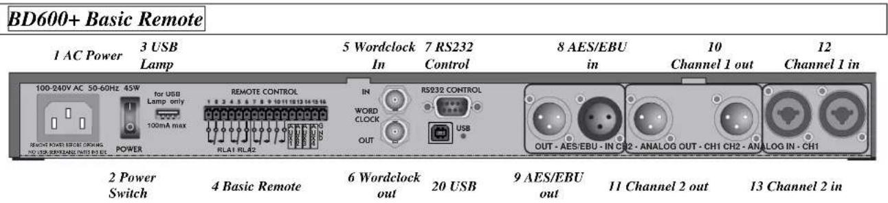
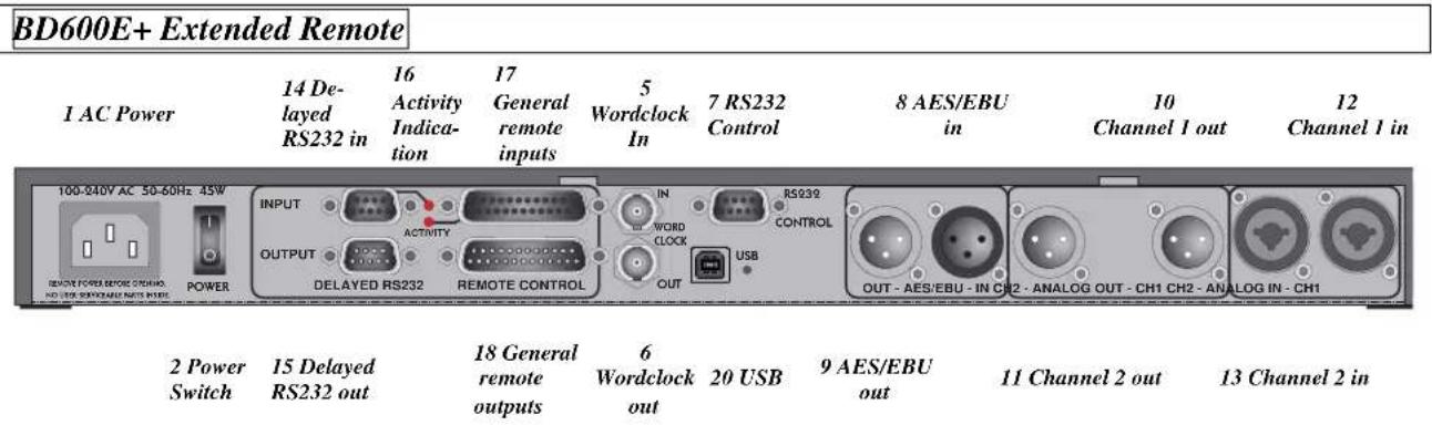
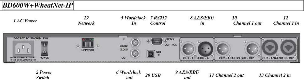
1) AC Power
IEC standard 3-prong connector. The center post is chassis ground. When power is not connected, the unit is bypassed - the analog and digital inputs are connected to their respective outputs through a relay.
2) Power Switch
This controls the AC power into the BD600+. When the power switch is off, the unit is bypassed, as described above.
3) USB Lamp
This is a standard USB connector into which a USB-powered lamp may be connected to enhance rear panel visibility in enclosed spaces. It supplies power only and cannot be used for USB communications.
4) Basic Remote Connector
The BD600+ has a standard remote control/signaling output. This allows remote-ing of the dump and sneeze functions and output of safe status.
These functions can be changed in configuration mode.
⇒ See page 34 to configure the Basic Remote.
5) Wordclock in
An external Wordclock signal may be used as a sample clock source. A Wordclock signal will usually offer a more stable clock source than that supplied by an AES/EBU signal.
See page 9 to use Wordclock
6) Wordclock out
The BD600+ outputs a Wordclock signal of its current sample clock – this may be used to syn- chronize other equipment to it.
This is a female 9-pin DB9 connector supplied to connect a remote computer or terminal. The remote computer or terminal can control all functions of the BD600+ including configuration. This connector is only functional if there is no USB connection.
See page 41 for information on RS232 remote control.
This connector may also be used for software maintenance purposes.
Digital Audio Inputs and Outputs
These are XLR differential AES/EBU connections for stereo input and output channels.
8) AES/EBU in
9) AES/EBU out
Use these connectors to connect professional digital audio equipment to the BD600+. The cables should be differential with a shielded twisted pair.
See page 9 to configure the BD600+ to use AES/EBU.
Analog Audio Inputs and Outputs
These are XLR differential audio connections for two input channels and two output channels.
10) Channel 1 Output
11) Channel 2 Output
Male XLR connectors.
12) Channel 1 Input
13) Channel 2 Input
Female XLR connectors.
Remote and other Connectors
14) Delayed RS232 in
15) Delayed RS232 out
These are 9 pin DB9 connectors where the input is delayed by the amount of the delay and fed to the output, usually to drive a clock indicator showing the time of the delayed material. They can also be used to delay RS232 control signals.
16) Activity Indication
These LEDs will flash when there is a change of state on the adjacent inputs.
17) General Remote Input
This DB25 female connector has 16 bipolar optoisolated inputs which can be individually programmed for use to either control BD600+ functions or to feed the corresponding General Remote Output.
See page 36 to configure these inputs.
18) General Remote Output
This DB25 male connector has 16 open collector outputs which may be individually programmed to supply BD600+ status or a delayed version of the corresponding input.
This is a Gigabit Ethernet connector for connection to the WheatNet IP network.
20) USB
This connector looks like a serial port when connected to a computer. It can be used for remote control and updating. Note that connecting this port to a computer disables the RS232 port – only one of them can be used at a time.
A device driver must be installed to use this with Windows 7.
See Installing Windows Drivers on page 54
Chapter 2 Operation
Analog
The BD600+ provides XLR differential audio connections for two input channels and two output channels. When bypassed, the audio pins of each input channel are connected to the audio pins of each output channel using a relay. The unit is automatically bypassed when power is disconnected or turned off. Note that neither pin 2 nor pin 3 should be left unconnected or you will get more noise and distortion than signal. Be aware that the 14 " jack inputs are not supported by the bypass function and should not normally be used.
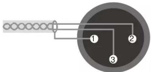
Male XLR output, balanced
Analog Outputs
These male XLR connectors provide a differential balanced audio output with a maximum level of +24dBu and a nominal level of -4dBu. Pin 1 is grounded to the case of the external XLR connector. Pin 2 is +phase and pin 3 is phase.
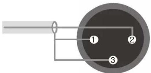
Male XLR output, unbalanced
Each connection may also be used as an unbalanced line. The BD600+'s XLR analog audio output connectors are male. Pin 1 is grounded. Connect pin 2 to your center conductor and connect pin 3 to pin 1. Both pins 2 and 3 must be connected at all times.
Analog Inputs
These female XLR connectors provide differential balanced audio input. The input level has a maximum value of +24dBu and nominal level of -4dBu. Pin 1 is grounded. Pin 2 is +phase and pin 3 is -phase.
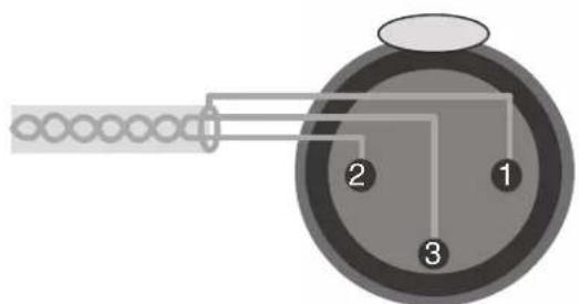
Female XLR input, balanced
Although the inputs of the BD600+ are balanced, you can still use them with an unbalanced line. The BD600+ XLR analog audio input connectors are female. Pin 1 and pin 3 would be grounded, while pin 2 is your audio signal. Both pins 2 and 3 must be connected at all times.
In the case of an XLR to XLR balanced line (differential) cable the shield should be left disconnected on one end (usually on the end connected to an instrument output). This helps to prevent ground loops. The use of balanced connections is recommended.
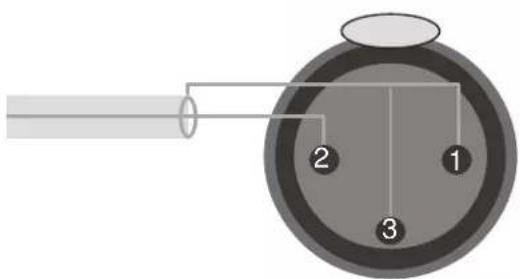
Female XLR input, unbalanced
Digital
These cables are differential with a shielded twisted pair. For short distances microphone cables can be used, but for longer distances and permanent installation a digital grade twisted pair cable is recommended.
AES/EBU input, XLR
The BD600+'s connector is female. Pin 1 is shield, 2 and 3 are differential.
AES/EBU output, XLR
The BD600+'s connector is male. Pin 1 is shield, 2 and 3 are differential.
BD600+Profanity Delay Chapter 2 Operation Page 7
Audio Connection
This chapter describes how the BD600+ is operated from the front panel using factory default configuration values. Optional remote control and configuration are described in later chapters and appendices.
Installation
Rack Mount
The BD600+ should be mounted in a grounded standard 19-inch rack using washers to avoid damaging the front panel overlay. The rack should be well ventilated and in a dry and dust-free environment so heat and moisture won't cause damage or degradation of performance. If rack units above or below the BD600+ are hot a suitable gap should be left to allow cooling.
Connect AC and Turn On Power Switch
The BD600+ will automatically configure itself to operate over an AC supply voltage range between 100V and 240V, 48-62Hz.
Since the unit is electrically out of the audio path when in bypass mode (unless configured otherwise), there is normally no reason to need access to the rear panel power switch. The power-up mode is selected by the configuration and is the same regardless of whether power is applied via the rear panel switch or via connecting the AC to an already switched-on unit. The unit may be left powered on even if the rack's power is to be disconnected.
Immediately after the unit is switched on, the front panel will be fully illuminated. After a second, the display will change to show LORD, followed by the software version number. At this time the unit will read the front panel buttons. If any buttons are pressed, the unit will perform a special start-up function (see Appendix D). If no buttons are pressed, the unit will complete its start-up, showing LORD again. After a second, the display will show ——and the BYPASS button should be illuminated. This combination of LEDs indicates that the unit is powered on and in bypass mode.
⇒ Note that the BD600+ can be configured to go immediately into on-line mode - see Chapter 3 for details.
Level Meters
There are two 10-segment LED bar graphs to display input level information. These graphs act as meters and may be used to align the equipment so appropriate audio levels are presented to the BD600+. The meters indicate the levels at the digital signal processor and are calibrated in decibels. The top LED is red. The next two are yellow, and the bottom seven are green.
The red LED is lit if the level is above +24dBu. The remaining LEDs indicate approximately -3dB, -6dB, -9dB, -12dB, -15dB, -18dB, -21dB, -24dB, -40dB below the +24dBu reference level. Before V1.4 the above reference level was the BD600+'s clip point, about 26dBu.
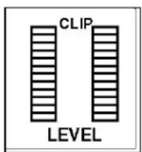
When the BD600+ is being operated correctly, most of the LEDs will be lit (NOT the red one) when a loud signal is being received.
Understanding BD600 Profanity Delay Functions
Connect analog audio inputs
Connect audio inputs to the two female XLR connectors on the rear panel. It is safe to connect and disconnect to the rear panel while the power is turned on. The inputs will probably come from a mixer board. Supply an audio source at a level just below clipping. The BD600+'s level meters indicate input level. Adjust your audio source's output such that with a maximum input signal, the level meters ideally have all of the green segments and both of the yellow segments lit, but not the red segment. Since the BD600+ has a very high dynamic range, it will give adequate performance on lower input levels.
Connect analog audio outputs
Connect audio outputs from the two male XLR connectors on the rear panel. It is safe to connect and disconnect to the rear panel while the power is turned on.
Connect digital audio inputs
Connect the digital audio input to the female XLR connector on the rear panel. It is safe to connect and disconnect to the rear panel while the power is turned on. There is no level control for the digital inputs as these cannot overload.
To enable the digital inputs and disable the analog inputs, or vice-versa, press the BYPASS button once or twice until the BYPASS button's LED is flashing, then press the CONFIG button until you see 3 RU, then press WAIT AND EXIT to see IMPT. Now use REBUILD or RAMP TO ZERO to select ANR or DIG as desired. After changing the input format you should also set the SYNC variable as appropriate (see below).
Connect digital audio outputs
Connect digital audio output from the male XLR connector on the rear panel. It is safe to connect and disconnect to the rear panel while the power is turned on. There is no level control for the digital output as it cannot overload. The digital audio output is always enabled, whether analog or digital input is in use.
Selecting the sample rate
The BD600+ uses digital processing for all internal operations and its sample rate can be selected in various ways. The digital output is also at this sample rate.
To change the sample rate, press the BYPASS button once or twice until the BYPASS button's LED is flashing. Now press the CONFIG button to enter configuration mode and press it again to go up through the configuration levels until you reach 3 AU. Press the WAIT AND EXIT button twice to go to the SYNC variable. The options are:
44.1K The sample rate is set to 44.1kHz using an internal quartz crystal source.
48K The sample rate is set to 48kHz using an internal quartz crystal source.
RES The sample rate is determined by the AES input.
WCLK The sample rate is determined by the Wordclock input.
DIG (BD600W+only) The sample rate is determined by the AES or the network, depending on the selected input.
Note that automatic internal sample rate conversion allows satisfactory reception of an AES signal even when the sample rate is not set to AES. This means that the unit could be set to 48K and satisfactorily receive a digital
Understanding BD600 Profanity Delay Functions
input at 44.1kHz. Note that the AES output rate will be that set by SYNC - in this case 48K, meaning that the input and output AES rates will be different.
Best results with digital inputs, will be normally achieved when the sample rate is set to match the input signal. Wordclock will often give a more stable sync source than the AES signal.
If either AES or WCLK is selected but does not have a suitable input signal, the display and the DIGITAL input status LED will flash, indicating lack of lock (meaning that the BD600+ is unable to synchronize with the signal).
During normal operation outside bypass mode, if the unit is synchronized to AES or WCLK and the signal becomes unsuitable, the display will scroll NO LOCK. In bypass mode, the displayed bars will flash.
If the sync source becomes unlocked, the system will revert to the configured fallback mode (FLBK). This may be either NUTE or ANALOG. If ANALOG is selected, during fallback mode the analog input LED will light while the digital LED will flash.
Notes and Warnings for AES/EBU Operation
The AES/EBU source must be stable before putting the unit in-line. If your AES/EBU source's sample rate changes, or if the AES/EBU is disconnected, or if the AES/EBU audio source is turned off while the BD600+ is processing audio (in-line and powered on), the BD600+ may add artifacts to the audio, or may indicate a failure with an error message (NO LOCK).
The BD600+'s purpose is to store audio and play it back with a delay. If the rate of audio into the unit changes while audio is stored, the audio played from the delay will change pitch. Thus, if the AES/EBU source's sample rate changes or stops altogether (cable is disconnected), the BD600+ may play out audio with a significant pitch shift! If the unit falls back from AES/EBU to analog input at a different sample rate, there will be a pitch change in the audio already delayed through the unit. Your digital system must be set very close to either 44100 or 48000 samples per second, or using the fallback option in the BD600+ will allow several seconds of pitch changed audio to pass.
From the above, it will be clear that when using digital audio on air it is essential that all signals are of suitable quality and that a solid lock be achieved. These issues apply to all digital audio connections, not just those involving the BD600+.
The BD600+ is designed to operate with sampling frequencies between 32K and 50kHz. If SYNC is set to AES or WCLK and an incorrect sync source of above 50kHz is presented the unit will switch to 48kHz sampling and attempt to sample rate convert the received AES signal to this rate. When it detects that an AES signal below 50kHz is again present, it will return to the original settings.
Using Wordclock
Wordclock is a square wave signal at the sample rate. Typically it is generated by a central timing source and sent directly to all units with a digital input. Using Wordclock as a sync source in this way allows tighter synchronization with reduced timing jitter which will maintain the best audio quality across the installation.
Using Wordclock in a “daisy chain” configuration where it is fed through each piece of equipment defeats its purpose, as it will be degraded, however subtly, as it passes through extra circuitry. The best configuration is where it is generated by a central high quality timing clock and then fed directly and separately to each unit that requires it.
Understanding BD600 Profanity Delay Functions
Wordclock Termination
Because a Wordclock signal is a high frequency digital signal, certain steps must be taken to be sure it is not degraded when it is fed along a cable. These issues become more important for long cables.
1) The characteristic impedance of the cable and connectors should match that of the Wordclock source. Wordclock cables are usually made with RG-59/U cable which has a characteristic impedance of 75 ohms. Other cables may be made with RG-58/U “Thin Ethernet” cable which has a 50 ohm impedance. Contact the manufacturer of your Wordclock source to find what impedance should be used – 75 ohm is the most common.
2) The end of the cable furthest from the Wordclock source must be terminated with a resistance matching the Wordclock source and cable impedance. The BD600+ has a jumper position inside (JP500, just behind the Wordclock connector) where a jumper may be installed to supply a 75 ohm terminating impedance – this jumper is normally not installed, meaning the input is un-terminated. It is usually more convenient to use an external BNC T-piece and terminator, avoiding the need to open up the unit to change or check the termination.
With multiple destinations only the one at the end of the cable needs to be terminated – intermediate destinations need not and should not be terminated. These should be connected by the use of a BNC “T” connector or splitter attached directly to their inputs so as to ensure the shortest possible stub length. Using multiple terminations is must be avoided, because (for example) twice 75 Ohm in parallel gives 37.5 Ohms which is the wrong value for termination and also increases loading on the source.
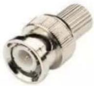
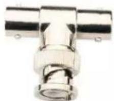
natural_image
Close-up of a metallic T-shaped connector or fitting (no text or symbols visible)Understanding BD600 Profanity Delay Functions
This section uses a tape recorder delay as an analogy to describe how the Eventide digital broadcast delay behaves when used as a profanity delay. The digital broadcast delay can be likened to a tape recorder with some new features. A basic tape recorder profanity delay would look like this:
When the delay is placed in line, the microphone (audio source) is connected to the record head while the transmitter is connected to the play head. This introduces a delay determined by the speed of the tape and the distance between the tape heads.
In our analogy the speed of the tape is constant. The distance between the heads is measured in seconds and there is enough room between the tape heads for eight seconds of delay. Factory default values are used whenever a time or duration is mentioned – for example, while the SAFE time is stated as four seconds, it can be configured to a different value.
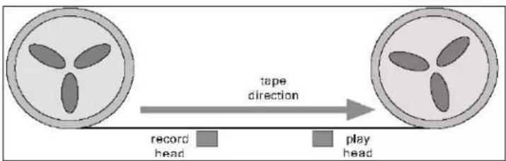
The Eventide system offers the following features:
Understanding BD600 Profanity Delay Functions
REBUILD - Increase the delay gradually
This feature allows the time between the play head and record head to be increased, in a subtle and transparent way. At the start the play head and record head overlap (no delay). The record head is slowly moved to the left until eight seconds of delay exists. The Eventide rebuild process does this in about 120 seconds without causing a pitch change in the audio. Rebuild is used to recover from a dump without having to go to a break. It can also be used to increase the delay time to allow for multiple dumps.
RAMP TO ZERO - Decrease the delay gradually
This feature is similar to rebuild except that the record head is moved to the right, in a subtle and transparent way, again taking a few minutes. When the record head reaches the play head, the unit is at live. RAMP TO ZERO is used to exit from delay when the call-in portion of a program is over. Ramp to zero performs a “time compression” operation, in that the audio plays out faster than real time.
WAIT FOR SAFE - Bring delay from live to 4 seconds quickly
When the wait for safe process is started, the tape is bypassed so the transmitter gets live audio. The record head is moved to the left by 4 seconds. After 4 seconds of recording, the transmitter is reconnected to the tape delay. There is now a 4-second delay. Note, since the initial 4-second segment of audio will be repeated at the play head, it is up to the user to prevent the live audio from going over the air. This feature is used to start a show coming from a network news feed, traffic report or other non-delayed program.
WAIT AND EXIT - Decrease the delay to 0 seconds quickly
This front panel feature is a method of quickly reducing the delay to 0.00 seconds. This process marks where on the tape the record head was when wait and exit is started. When that piece of tape reaches the play head, the record head is moved to the play head, decreasing the delay suddenly to 0.00 seconds. Use this command when a call-in show needs delay but where a break to non-delayed operation is required.
SNEEZE - Edit the delay before a bad noise happens
This feature is used to stop the record process temporarily. While the SNEEZE button is pressed, the record head moves toward the play head at the same speed as the tape, not recording any audio, until the SNEEZE button is released (at which point the record head stops), or until the record head reaches the play head, at which point silence is played out.
DUMP - Edit the delay after a bad noise happens
DUMP is used to edit several seconds of audio from the delay. Pressing DUMP moves the record head four seconds toward the play head (or up to the play head, whichever is less). This causes the most recent four seconds of audio from the microphone to be discarded, including the bad noise.
PANIC - lose all delayed audio and play a jingle while delay is rebuilt
The PANIC function allows recovery from an undesirable signal by instantaneously moving the record head up to the playback head to dump all the delayed material. It then moves the record head a distance from the playback head corresponding to the length of a jingle or configured mute time.
It then either plays a jingle from a Compact Flash card or mutes the output for a configurable time, allowing an external cart machine to be cued.
Understanding BD600 Profanity Delay Functions
Once the jingle or mute is complete, the delay will be partially filled, allowing the show to continue seamlessly after the inserted jingle.
See page 17 for more information on the PANIC feature.
Insert or Station Break Insert – insert another audio source into the program material
Insert functions cause the playback head to move away from the record head at the speed of the tape. This means that new audio continues to be stored into the delay while the inserted material is playing and none of the material already on the tape is lost. Once the insert operation is over, the playback head stops moving and the oldest audio from the tape starts to play out.
The amount of delay in use will be increased by the length of the insert. Clearly in this example there will be a mechanical limit to the movement of the playback head which will determine how long an insert may increase the delay time – on the BD600+ this maximum delay time is about 80 seconds.
This function may only be accessed through remote control.
Operating as a Profanity Delay
The BD600+ may be used as a broadcast profanity delay - this is its primary function and factory default mode. When power is first applied to the BD600+, the unit's audio inputs and outputs are bypassed through a relay. Pressing the BYPASS button places the unit in-line with 0.00 seconds delay. If the audio levels are adjusted properly, there should be no perceptible difference when the unit is switched in. Note that since the BD600+ by default uses true relay bypass, there might be a slight click. The 4-digit display will now read 0.00 which indicates no delay. The red indicators on several of the buttons will be lit, showing which buttons are valid choices. The lighting of the indicators changes depending on the BD600+'s state (or mode). Since the unit is at 0.00 seconds delay and in-line, it will be in live mode. The following is a list of the few different modes in which the unit may be placed: Note that the BD600+ may be configured to power up or exit bypass in different modes. See Chapter 3 Configuration for more details.
Modes
- bypass and configuration - delay is set to 0.00 seconds, the audio is bypassed directly from input connectors to output connectors.
• live - bypass relays are open (unit is in-line), delay is set to 0.00 seconds. - static - bypass relays are open (unit is in-line), delay is not changing.
- rebuild - bypass relays are open (unit is in-line), delay is slowly increasing.
- ramp to zero - bypass relays are open (unit is in-line), delay is slowly decreasing. Unit goes to live when it reaches 0.00 delay.
- wait for safe - bypass relays are open (unit is in-line), delay is filling with audio, but outputs are seeing input audio without delay. Unit switches to rebuild mode when safe delay time is reached. If wait for safe is cancelled, the unit will return to live mode.
- wait and exit - bypass relays are open (unit is in-line), input audio is not going into delay, but output audio is coming from the delay. The delay length is reducing rapidly. The unit will go into live mode when it reaches 0.00 delay. The SNEEZE button is disabled. If wait and exit is cancelled, the unit will return to the delay value it had when wait and exit was started.
- sneeze - bypass relays are open (unit is in-line), input audio is not going into delay, but output audio is coming from the delay. The delay length is reducing rapidly. When the SNEEZE button is released the unit will go back to the previous mode.
- panic - bypass relays are open (unit is in-line), input audio is going into the delay but is not heard until the panic operation is complete. A jingle is played from the Compact Flash card or the outputs are muted to allow an external audio source to be used. The unit will enter rebuild mode once the jingle is complete or the configured mute period is over.
- insert or station break - bypass relays are open (unit is in-line), input audio is going into the delay but is not heard until some time after the insert operation is complete. A jingle is played from the Compact Flash card or the outputs are muted to allow an external audio source to be used. The delay length is increased by the length of the inserted audio.
Functions and Features
By default on power-up the BD600+ is in bypass mode. Press the BYPASS button to put the BD600+ in static mode. The delay is now at 0.00 seconds. After delay build is initiated and until the delay is reduced to 0.00 seconds, all audio should pass through the BD600+ before going to the transmitter to avoid audible discontinuities.
Operating as a Profanity Delay
Starting a Show Segment with REBUILD
This process is used to start a show in a simple manner, allowing the guest or dial-in caller to be enabled in less than two minutes. The host customarily uses this period for an introduction or monologue.
As a show starts, the delay is set to 0.00. Pressing the REBUILD button starts a process by which the delay is slowly increased. During the rebuild process the REBUILD button's indicator will flash.
In less than two minutes the BD600+ will have enough delay built up to be 'safe' for a caller to be placed on the air. The DUMP button will light up to confirm this and the delay amount will show 4.00 seconds and be increasing. If so configured, a rear panel output line will allow an external relay to be closed, enabling the phone line.
After a few minutes, the delay will reach maximum and the REBUILD button's indicator will turn off. The rebuild process is complete, and the delay enters static mode. However, the unit remembers that it rebuilt to maximum, so, if SNEEZE or DUMP is used, after the SNEEZE or DUMP button is released, the delay will automatically rebuild back to maximum.
Starting a Show Segment with WAIT FOR SAFE
This process is used to start a show rapidly. The guest or dial-in caller are enabled immediately after the studio goes on air. Before beginning, the transmitter is not getting its source from the BD600+.
The operator needs to know, or to set, the configuration value of safe time (default is 4.00 seconds). At safe time (or more) seconds before the studio goes on-the-air the operator presses the WAIT FOR SAFE button.
The host begins talking immediately. When the DUMP button illuminates:
The WAIT FOR SAFE process has completed.
The SAFE relay output is enabled.
The engineer or host fades the output of the BD600+ into the transmitter. (See note below)
The host may begin taking dial-in callers. The BD600+ drops into rebuild mode and slowly completes building up to maximum delay.
Note: During the 4-second period that wait for safe is running and the WAIT FOR SAFE button's indicator is flashing, the microphone audio is passed directly to the BD600+ outputs. It is usually undesirable to have that audio pass over the air. Use a mixer or other control to disable that audio until the show is scheduled to start.
Starting a Show Segment with PANIC
If a suitable jingle or other audio is recorded onto a Compact Flash card in the card slot, the segment may be started by hitting the PANIC button, causing play back of the jingle from the card. During this time the host may start talking, typically an introductory monologue, which will be recorded into the delay. Once the jingle has completed, the monologue starts to play out and the unit goes into rebuild mode.
See More Information on the PANIC feature. on page 17
Ending a Show Segment with RAMP TO ZERO
This process gradually reduces the delay and takes a variable amount of time up to a few minutes. During the show, the BD600+ would usually remain in rebuild mode at maximum delay. Whenever SNEEZE or DUMP is used, the unit rebuilds back to maximum. To end the show, press RAMP TO ZERO. The delay will reduce in several minutes to 0.00 while the RAMP TO ZERO button's indicator flashes. During ramp to zero the DUMP and SNEEZE buttons will continue to be available, but an eye should be kept on how much time is actually still available to be dumped or sneezed away. To stop the ramp to zero process, press the RAMP TO ZERO button. The unit will go to static mode (delay not changing). The ramp to zero process may be resumed, or another function may be started.
BD600+Profanity Delay Chapter 2 Operation Page 15
Document Version 2.3
Operating as a Profanity Delay
Once the ramp to zero process is complete, the unit will be operating at zero delay (live).
Ending a Show Segment with WAIT AND EXIT
This process rapidly reduces the delay and takes the time displayed on the BD600+'s front panel indicator, typically 8 seconds or less.
At the end of the show, after the last word is spoken, press the WAIT AND EXIT button. All of the audio delayed in the BD600+ is played out in real time until the delay reaches 0.00. The WAIT AND EXIT button's indicator flashes until the process is complete. Input audio is ignored by the BD600+ during this process. When the delay reaches 0.00, the unit goes into live mode at which time input audio is passed directly to the outputs.
If the WAIT AND EXIT button is pressed erroneously, the process may be cancelled by pressing the WAIT AND EXIT button again. The unit will go back to the delay it had before WAIT AND EXIT was pressed and will be static (delay not changing).
DUMP Button
This button has several functions. The primary purpose of this button is to stop a profanity from going out over the air. This button is illuminated when in-line with a safe amount of delay (specified by safe time). Here is a list of modes and how the DUMP button works in each:
In rebuild or ramp to zero
DUMP causes the unit to delete several seconds (configurable) from the delay line starting with the most recently input audio information. The amount dumped is configurable and defaults to 4.00 seconds. When the DUMP button is pressed, the dump amount is subtracted from the current delay. If the displayed delay is lower than the dump amount, the delay is reduced all the way to 0.00. After DUMP is released, the unit continues with the previous mode. Note: even if the unit is no longer rebuilding, having already reached full delay, the unit will still return to rebuild mode after DUMP is released.
In wait for safe
DUMP will cancel the wait for safe operation and return the unit to zero delay.
In precision delay configuration mode
DUMP causes the delay to be reduced to its minimum value (0.010 seconds).
In bypass, live, or wait and exit
DUMP has no function.
SNEEZE Button
This button is used to cover up a predictable interruption to a program like a sneeze, cough or comment to the caller or engineer, or some other undesirable noise. If the unit is in-line (not bypassed) in profanity delay mode and not in wait for safe or wait and exit mode, this button will stop accepting input audio while it is held. The delayed audio will continue to be played out, reducing the delay amount. This would make the listener unaware that the mute occurred. If the delay reaches 0.00, or is at 0.00 when SNEEZE is pressed, the audio is muted. When SNEEZE is released, the unit goes back to the interrupted mode. In simple terms – press button, sneeze, release button.
Delay Amount Display
The display consists of a bar graph and a 4-digit numerical display. The numerical portion shows the delay amount in seconds with optional fractions of seconds. The factory default is to show seconds and thousandths of seconds with the decimal point appropriately placed. The bar graph indicates what portion of maximum the unit is delaying. For instance, if the unit is delaying at 3.50 seconds and the unit is configured to have a maximum of 8 seconds of delay, 6 of the 15 bar graph segments are lit.
Operating as a Profanity Delay
The display is configurable to be blank, or to show 1, 2, 3 or 4 digits of resolution of delay length. In bypass the display will show ‘----’.
If the unit is in-line, and configured to use AES or Wordclock as a sync source and it loses lock, the display will scroll "NO LOCK."
See Notes and Warnings for AES/EBU Operation on page 10
More Information on the PANIC feature
The PANIC feature is designed to offer some protection against undesirable input audio when the delay value is unsafe. It is also useful as a convenient way to get into delay at the start of a show.
Hitting the PANIC button causes the delay to be instantly set to zero and then filled with input audio in real time. During this time, a jingle may be played from the Compact Flash card, or the output muted.
If the input is being monitored, DUMP or SNEEZE may be used in the normal way.
If a suitable jingle file is selected on the card it will be played, and the panic mode will terminate at the end of playback. If the length of the jingle is greater than the configured maximum delay value it will play to the end, but the delay will only be filled to the configured maximum value.
⇒ See Chapter 3 to select the jingle file.
If no suitable jingle is selected on the card (or the card is not present) and the PANIC (PANC) time is not configured to OFF, the output will be muted for the PANIC time, allowing an external cart to be played if desired. After this time, the panic mode will terminate, with the delay filled to the configured PANIC time.
See Chapter 3 to configure this.
Once the panic mode has terminated, the unit will go to rebuild and the delay will play out, starting with the audio immediately after the PANIC button was hit. A panic operation may be ended early by hitting the PANIC button again. (Prior to V1.4, this would mute the audio until the operation completed).
If the PANIC time is configured to OFF and no suitable jingle is selected on the card, the PANIC feature will be disabled and the button will be unlit.
Jingle files on the card
Jingle files can be recorded on a PC (IBM-compatible Personal Computer) using any suitable software. These can be saved to a suitable Compact Flash (CF) card using a commercial CF card reader/writer. These are usually connected to the PC via USB (Universal Serial Bus) and are widely available.
The files must be 16-bit stereo .WAV files longer than 1.0 seconds, created with the sample rate to which the BD600+ is to be operated. If these requirements are not met, either the BD600+ will not recognize them, or they will be played at the wrong speed.
The BD600+ can support up to four different jingles per card – they must be named ONE.WAV, TWO.WAV, THREE.WAV and FOUR.WAV respectively. These names may be in upper or lower case. The active jingle can be selected either by changing the configuration variable JING, or by remote control. If the selected jingle is either not valid or not present, or there is no card in the slot, a BRD JINGLE message will appear briefly. The JBAD status will be displayed if configured.
See Chapter 3 to configure jingle selection.
⇒ See Appendix A for information on remote control.
Cards should not be removed or inserted when the unit is not bypassed.
Operating as a Profanity Delay
The BD600+ is not a live performance instrument and requires a second or so to respond to a jingle change.
When Jingles should not be used
When Jingles are to be used it is recommended that the JBAD status be displayed (BD600E+, W only), as this gives advance warning of possible problems. These may occur for the following reasons:
- The card is not present or not readable
- No jingle is selected => See Chapter 3 to configure jingle selection
• The selected jingle is not on the card - The selected jingle has the wrong format
- The selected jingle is being prepared for use (about one second is needed after inserting a card or changing jingle selection or between playbacks).
• A jingle is currently being played.
Operation as a Micro Precision Fixed Delay
The BD600+ may be used as a fixed stereo delay line, adjustable from 0.010 seconds to 19.999999 seconds, adjustable in microseconds (0.000001 seconds) or thousandths of film/video frames. Operation is straightforward, with several front panel buttons serving secondary duty as fixed delay controls.
There are two ways to enter precision delay mode - the first method is from configuration mode. Go into bypass mode.
• In bypass mode the display shows ——.
- Press the CONFIG button. This puts the unit into configuration mode (display shows CONF).
- Now press the CONFIG button again. You are now at the "on-line" configuration level (display shows 1 ON).
- Now press the WAIT AND EXIT button. The display should now show RUN.
- Now press the RAMP TO ZERO button repetitively (stepping through run options) until the display shows MPD.
- Press the BYPASS button to exit configuration mode. The display should show —.
- Now press BYPASS to put the unit in-line. The unit will be in micro precision delay mode.
To return to profanity delay operation, press BYPASS, then CONFIG twice, then WAIT AND EXIT. The display now shows RUN. Now press SNEEZE to return to the factory default setting of the run parameter. Now press BYPASS to get out of configuration mode.
The second way to enter precision delay mode is to select MPD as the maximum delay time (OLAY). Then the maximum delay is determined by the fixed delay settings, and normal broadcast delay functions may be used to enter and exit precision delay mode. For example, if you REBUILD to maximum, once the fixed delay value is reached the unit will enter precision delay mode. RAMP TO ZERO or WAIT AND EXIT may be used to return to profanity delay functionality. In this mode, the fixed delay value becomes the SAFE value, and the DUMP button illuminates when it is reached.
Controlling the Fixed Delay
In precision delay mode the profanity delay buttons have their normal functions for delay values of 100mS and above. Below 100mS they are inactive. This allows you to ramp up to or down from the precision delay time, which now becomes the SAFE value.
There is one addition – the CONFIG button is also active. If CONFIG is selected it will flash, and the meanings of the buttons change to allow the fixed delay value to be changed. In this mode, the only operable buttons are BYPASS, WAIT FOR SAFE, WAIT AND EXIT, REBUILD, DUMP and RAMP TO ZERO. The buttons behave as follows:
- BYPASS takes the unit off-line. Always valid.
- WAIT FOR SAFE selects the digit to the left. Valid if lit.
- WAIT AND EXIT selects the digit to the right. Valid if lit.
- REBUILD decrements selected delay digit. Valid if lit.
- RAMP TO ZERO increments selected delay digit. Valid if lit.
• DUMP sets the delay to its minimum value (10mS).
Operation as a Micro Precision Fixed Delay
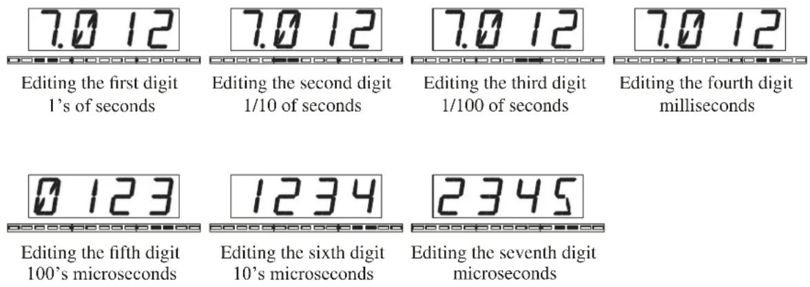
The bar graph below the four-digit display flashes to indicate precision delay configuration mode and shows which of the four visible digits is selected for adjustment. The presence of the decimal point indicates that the four digits shown are the ones, tenths, hundredths and thousandths digits. Use the WAIT FOR SAFE and WAIT AND EXIT buttons to step through the selected digits. The following illustration shows a 7.012345-second delay as the WAIT AND EXIT button is pressed six times. Press WAIT FOR SAFE repeatedly to step back to the first digit. Press CONFIG again to get back to normal precision delay mode.
Notes on Precision Delay mode
- The minimum delay setting the BD600+ will allow is 10 milliseconds. The absolute delay time through the unit will depend on whether analog or digital inputs or outputs are being used.
- Broadcast profanity delay functions such as rebuild, dump or sneeze are only operative in precision delay mode at delay values of 100 milliseconds and above.
- The fixed delay writes data continuously into the 20-second buffer. Changes in delay value changes the position of the play head, not the record head. That means that, if the delay length is adjusted by ear, the user doesn't have to wait for new input audio to check the adjustment. As an example, while listening to an audio source, try adjusting the seconds digit upward. It is easy to play the same 1-second piece of input audio ten times.
- Small changes to delay values are smoothed, meaning that in most cases such changes can be made on air. A large change will still be smoothed, but a soft click or a discontinuity in program material may be apparent.
Chapter 3 Configuration
There are a number of adjustable values used by the BD600+. Configuration mode gives access to these values and allows them to be changed. This chapter covers the configurable variables for the basic BD600+. Configuration of optional features is covered in the appendices.
The configuration mode is operated by the front panel buttons, which are used to navigate through a map of configuration variables. The WAIT FOR SAFE and WAIT AND EXIT buttons are used to move left and right across the map. The REBUILD and RAMP TO ZERO buttons are used to adjust the values of individual variables. The CONFIG button will move to the left side of the map and, if pressed while already on the left side, will move up through the levels. The SNEEZE button is used to reset a selected variable to the factory default.
See the side-bar for a partial map of the configuration parameters. Complete information is provided in a following table. This map is a combination of the maps for both the BD600+ and BD600E+.
Basic Operation Example
From bypass mode, press CONFIG. The display changes to show CONF. Press CONFIG again to move up the map. The first press will move to 1 ON. The next will move to 2 Tl. Now press the WAIT AND EXIT button a few times to move over to the REB variable (rebuild time). Notice that the SNEEZE button's LED is not lit. This means that the REB variable is set to the factory default. Use the RAMP TO ZERO button to change the value. Notice that the SNEEZE button lights up. Press the SNEEZE button to reset the parameter back to factory default.
Another Example
If the BYPASS button is not illuminated, press BYPASS. Next, press CONFIG. Once the display shows CONF, press the RAMP TO ZERO button. The display changes to 1 ON.
Now press the WAIT AND EXIT button once.
The display changes to RUN. To check the run mode, press the REBUILD or RAMP TO ZERO button. The display changes to show LIVE, indicating “go into live mode when exiting from bypass." To change the run mode, press the RAMP TO ZERO button. Use the REBUILD and RAMP TO ZERO buttons to go up and down through the four possible values for the run parameter.
Press BYPASS to exit from configuration mode and return to bypass mode. Any changes made will remain until they are reconfigured.
Password Protection
If desired, configuration mode may be password protected. The display will then show P--- when the CONFIG button is pressed. To enter configuration mode, the user must first press and hold the CONFIG button, then a single other button (password) and then release the CONFIG button. Pressing the wrong button will return the unit to bypass mode. This procedure has been made deliberately obscure to ensure authorized use. Change or disable the password button using the PR55 configuration variable. => See page 30 for more information.
Chapter 3 Configuration
Restoring Factory Defaults
All factory defaults may be restored by holding down the PANIC button while power is turned on. This will also reset the above Password.
Keep holding PANIC down until the display shows "RETURN TO FACTORY DEFAULTS ?." The message text will be scrolled marquee-fashion across the display. All buttons will be off except WAIT AND EXIT which will be flashing, indicating "yes" and REBUILD which will be lit steadily, indicating "no." Press WAIT AND EXIT to answer "yes."
Individual configuration values may be set to factory default by using the SNEEZE button while the value is selected. The LED on the SNEEZE button is lit if the variable is not set to factory default.
Table of Configuration Variables
Note: Full descriptions of the selectable values are available in pages following this table. Some of these values are specific to either the BD600+ or BD600E+.
| 4 Character Identifier | Description | Units | Range of Values | Default Value |
| CONF | Start of Configuration ModeThis selection has no configurable value. It indicates entry into configuration mode | |||
| 1 ON | Online Parameters | |||
| RUN | Run ModeSelects the mode the unit goes into from bypass. Select mPD to enable precision fixed delay | mode | LIVE REB WFS mPD | LIVE |
| POWP | Power-Up ModeSelects which mode the unit goes to after power-up. | mode | INLN BYP PREV | BYP |
| BYP | Bypass ModeSelects the bypass mode | mode | RLA OSP MUTE | RLA |
| DISP | Display DigitsSelects the number of digits after the decimal point in profanity de-lay mode | # of digits | OFF 0 1.1 2.22 | 2.22 |
| LITE | Display BrightnessSets the display brightness | level | LOW MID HIGH | MID |
| PASS | PasswordAllows a password to be selected which would limit access to the configuration mode | button | NONE BYP WFS WAREB RTO SNEZDUMP | NONE |
| JING | Jingle FileThe name of the current jingle file | name | OFF ONE TWO THREFOUR | OFF |
| LOCK | Lock Front PanelDisable the front panel keys | NO YES | NO | |
| SHOW | Delay Display TypeShow delay used or delay free | USED FREE | USED | |
| 2 TI | Time Parameters | |||
| OLAY | Delay LengthMaximum length to which the pro-fanity delay will rebuild | seconds | MPD 4.0 6.0 8.0......40.0 60.0 80.0 | 8.0 |
Table of Configuration Variables
| REB | Rebuild TimeAmount of time it will take to re-build the delay from 0 seconds to maximum | seconds | varies with delay1.0 ... 267M | varies |
| SAFE | Safe TimeAmount of time the profanity de-lay must have built up in order to be SAFE. Controls the lighting of the DUMP button and RLA2 outputs | seconds | 1.0 1.5 2.0 2.5......8.5 9.0 9.5 10.0 | 4.0 |
| DUMP | Dump AmountNumber of seconds of audio that will be dumped when the DUMP button is pressed | seconds | 1.0 1.5 2.0 2.5......8.5 9.0 9.5 10.0 | 4.0 |
| PANC | Panic Mute TimeThe time in seconds for which the output mutes if no selected jingle is found when PANIC is pressed | seconds | OFF 2.0 2.5 3.0......6.5 7.0 7.5 8.0 | 4.0 |
| FRAM | MPD Frame DisplayShow MPD display in frames. | f.p.s. | OFF 24 25 29 30 | OFF |
| PULS | Heartbeat IndicationPulse CONFIG led to show life | seconds | OFF 1.0 2.0 5.0 10.0 | OFF |
| SBR | Station Break DurationThe duration of a Station Break Insert.(BD600E+,W+ only) | seconds | 2.0 2.5 3.0......6.5 7.0 7.5 8.0 JING | 4.0 |
| TIM1 | 1st Time IndicationA time marker that may be used to drive a remote output when the delay exceeds it(BD600E+,W+ only) | seconds | 2.0 2.5 3.0......78.5 79.0 79.5 80.0 | 3.5 |
| TIM2 | 2nd Time IndicationA time marker that may be used to drive a remote output when the delay exceeds it(BD600E+,W+ only) | seconds | 2.0 2.5 3.0......78.5 79.0 79.5 80.0 | 7.5 |
| 3 AU | Audio Parameters | |||
| INPT | Audio Input SourceSelect analog or digital audio inputs | source | ANA DIGANA RES UNET | ANA |
| SYNC | Audio Synchronization SourceDetermines the audio sample clock | source | 44.1K 48K RES(DIG)WCLK | 44.1K |
Table of Configuration Variables
| FLBK | Fallback ModeWhat to do if SYNC source is lost | action | ANA MUTE | MUTE |
| 4PRO | Performance Parameters | |||
| THRS | Threshold LevelAudio level (below maximum level) that is recognized as silence | decibels | -60 ... 0 | -60 |
| TMPO | Tempo ModificationControls how much the tempo is allowed to vary in order to improve the quality of audio processing | percentage change allowed | 0 10 ... 190 200 | 0 |
| SRCE | Source for ProcessingLeft/right mix of channels to be used in determining the best times to do audio processing during re-build or ramp to zero | channel | LEFT LCEN CENTRCEN RITE | CENT |
| SREM | Remote Control Parameters | |||
| AUX1 | Function of AUX1 input(not present on BD600E+,W+) | OFF BYPCNF WFSWRE REBRMPOSNEZDUMP LIVESTATPANC FULLMUTESBRK RTB0-R W-R 0-R ONE TWOTHREFOUR | BYP | |
| AUX2 | Function of AUX2 input(not present on BD600E+,W+) | OFF BYPCNF WFSWRE REBRMPOSNEZ | DUMP |
Table of Configuration Variables
| DUMP LIVE STATPANC FULLMUTE SBRK RTB0-R W-R 0-R ONE TWOTHREFOUR | ||||
| RUX3 | Function of AUX3 input(not present on BD600E+,W+) | OFF BYP CNF WFS WAE REBRMPO SNEZ DUMP LIVE STATPANC FULL MUTE SBRK RTB 0-RW-R 0-R ONE TWO THREE FOUR | SNEZ | |
| RUX4 | Function of AUX4 input(not present on BD600E+,W+) | OFF BYP CNF WFS WAE REBRMPO SNEZ DUMP LIVE STATPANC FULL MUTE SBRK RTB 0-RW-R 0-R ONE TWO THREE FOUR | PANC | |
| RLA1 | RLA1 Relay FunctionThe state during which RLA1 is energized(not present on BD600E+,W+) | OFF ON BYP CNF WFS WAE REBRMPO SAFE SNEZ DUMP LIVESTAT PANC FULL MUTE SBRK | DUMP | |
| RLA2 | RLA2 Relay FunctionThe state during which RLA2 is energized. Note that this also controls the DUMP button light.(not present on BD600E+,W+) | OFF ON BYP CNF WFS WAE REBRMPO SAFE SNEZ DUMP LIVESTAT PANC FULL MUTE SBRK | SAFE | |
| BAUD | Baud RateThe Baud Rate for the RS232Control Connector | OFF 2400 4800 9600 1920038400 57600 76800 115200 | OFF | |
| SEND | Delay Time Export FormatHow to export delay changes | OFF ENDO CR CRLF LF | OFF | |
| SEXT | Extended Remote Control Parameters(BD600E+,W+ only) | |||
| BAUD | Number of bitsThe character size used by theRS232 Delay Connector | 2400 4800 9600 19200 3840057600 76800 115200 | 9600 | |
Table of Configuration Variables
| BITS | Parity SettingThe parity setting for the RS232 Delay Connector(BD600E+ only) | 5 6 7 8 | 8 |
| PARI | Remote Input FunctionThe functions of remote input 1. If the function is set to OFF, the input may still be used as a source for the delayed remote output. | NONE EVEN ODD CLEAR SET | NONE |
| IN1 | Remote Input FunctionThe functions of remote input 2. If the function is set to OFF, the input may still be used as a source for the delayed remote output. | NONE BYP CNF WFS WAE REBRMPO SNEZ DUMP LIVE STATPANC FULL MUTE SBRK RTB D-RW-R O-R ONE TWO THRE FOUR INS | BYP |
| IN2 | Remote Input FunctionThe functions of remote input 3. If the function is set to OFF, the input may still be used as a source for the delayed remote output. | NONE BYP CNF WFS WAE REBRMPO SNEZ DUMP LIVE STATPANC FULL MUTE SBRK RTB D-RW-R O-R ONE TWO THRE FOUR INS | DUMP |
| IN3 | Remote Input FunctionThe functions of remote input 4. If the function is set to OFF, the input may still be used as a source for the delayed remote output. | NONE BYP CNF WFS WAE REBRMPO SNEZ DUMP LIVE STATPANC FULL MUTE SBRK RTB D-RW-R O-R ONE TWO THRE FOUR INS | SNEZ |
| IN4 | Remote Input FunctionThe functions of remote inputs 5 to 16. If the function is set to OFF, the input may still be used as a source for the delayed remote output. | NONE BYP CNF WFS WAE REBRMPO SNEZ DUMP LIVE STATPANC FULL MUTE SBRK RTB D-RW-R O-R ONE TWO THRE FOUR INS | PANC |
| INS......IN16 | Remote Output FunctionThe function of remote output 1 | NONE BYP CNF WFS WAE REBRMPO SNEZ DUMP LIVE STATPANC FULL MUTE SBRK RTB D-RW-R O-R ONE TWO THRE FOUR INS | various |
| OUT1 | Remote Output FunctionThe function of remote output 2 | OFF ON DLIN BYP CNF WFS WAE REB RMPO SAFE SNEZ DUMP LIVE STAT PANC FULL MUTE SBRKTIM1 TIM2 INS JBAD >MAX TOP UNLK | DUMP |
Table of Configuration Variables
| OUT2 | Remote Output FunctionThe functions of remote outputs 3 to 16 | OFF ON OLIN BYP CNF WFS WAREB RMPO SAFE SNEZ DUMP LIVESTAT PANC FULL MUTE SBRKTIM1 TIM2 INS JBAD >MAX TOPUNLK | SAFE |
| OUT3......OU16 | OFF ON OLIN BYP CNF WFS WAREB RMPO SAFE SNEZ DUMP LIVESTAT PANC FULL MUTE SBRKTIM1 TIM2 INS JBAD >MAX TOPUNLK | various | |
Configuration Variables
A number of configuration variables are specific to either the Basic Remote or Extended Remote models – these are covered in separate appendices.
BYP Bypass mode
When the BD600+ is bypassed, internal relays normally connect the analog and digital outputs to their respective inputs. This also occurs when the unit is powered down. In some circumstances it may be preferable to change this behavior, for example, if the unit is fed with an analog signal but the output is taken from the digital output. In this case, DSP bypass may be preferred, where the inputs and outputs are connected electrically according to the IMPT configuration. The BD600+ may also be configured to MUTE its outputs when bypassed.
DISP Display Digits
The number of digits after the decimal point showing the current delay amount in profanity delay mode. The BD600+ has a four-digit numeric display used to show the delay amount in hundredths of seconds. As the delay rebuilds or ramps to zero, the last digit can change rapidly enough to be distracting to the operator. By changing the number of display digits to two, one, or even none, this source of distraction can be reduced greatly or eliminated. Since the operator may only need to know that the BD600+ is in rebuild, and whether it is safe or not, the operator may choose not to have the delay time presented in such high resolution.
DELAY Delay Length
Delay length controls the maximum length of the broadcast delay. This adjustment may select a delay length of from 4.0 to 80.0 seconds. Select a length allowing the operator to dump multiple offending phrases without impairing operator efficiency. A length which is too short will not allow the operator enough time to delete offending speech, while a length that is too long increases the amount of time required to exit from the delay at the start of a break or end of a show. This delay length may be exceeded by the use of an Insert or Station Break operation.
If MPD is selected, the maximum delay is determined by the precision delay setting, allowing the normal profanity delay functions to be used to enter and leave precision delay mode.
Dump Dump Amount
This is the amount of time deleted from the delay when the DUMP button is pressed in profanity delay mode. If the DUMP button is pressed when less than this amount of time is in the delay, then the entire contents of the delay are deleted.
FLBK Fallback
If AES/EBU or Wordclock is selected as a sync source and there is no suitable signal present, the unit will declare an out-of-lock condition. If the unit is in-line (not in bypass) and an out-of-lock condition exists, the four-digit display will scroll the message NO LOCK. If the FLBK (fallback) variable is set to RNA (analog), then the analog input audio will be used until lock is restored. The analog input will be sampled at either 44100 or 48000, the sample rate chosen being whichever of the two rates is closer to the AES/EBU sample rate last received by the unit (or 48kHz if no AES/EBU signal has been present since power-up). The AES/EBU outputs will be active and the rate will be the same as the input analog sample rate. If the fallback variable is set to MUTE, the unit will mute the outputs until lock is regained.
FRAM MPD Frames Display
The MPD setting is normally be displayed in seconds (FRAM = OFF). It can instead be displayed in film or video frames by setting FRAM to 24, 25, 29 OR 30 as appropriate. Use 29 for the NTSC drop frame rate of 29.97 fps.
Configuration Variables
INPT Input source
This variable determines whether the ANALog or DIGital input is used. If it is changed, it will usually also be necessary to change the SYNC variable accordingly. BD600W+adds UNET as a source, selecting the configured WheatNet-IP network source.
⇒ See Selecting the sample rate on page 9,
JING Select current Jingle
Select which of the four possible jingles (ONE, TWO, THREE or FOUR) on the Compact Flash card is active. Note that the jingle file will only be recognized if it is in the correct format. A BAD JINGLE message will appear briefly if an unsuitable or absent jingle file is selected.
Jingles should not be changed while they are being played as this will cancel the playback operation.
See Jingle files on the card on page 17 for more information.
LOCK Lock Front Panel
The front panel lockout feature allows most front panel buttons to be disabled, allowing protection against undesired operations when the unit is to be exclusively remote controlled. When LOCK is ON, all keys except for BYPASS and CONFIG will be disabled. Pressing any other key will cause the display to flicker, and an 'L' to be displayed.
PANC Panic Mute Time
If no suitable jingle is found on the Compact Flash card (or if the card is not inserted), this variable determines how long the outputs will mute when PANIC is pressed. In this case, if it is set to OFF, the PANIC feature is disabled, otherwise this variable will be ignored if the selected jingle is present.
PASS Password
Where some modicum of security is needed, this value may be changed to the identifier of a front panel button. If set, a user would have to go to BYPASS, press and hold CONFIG, then press the selected additional front panel button before releasing CONFIG, in order to get into configuration mode. A selection of NONE indicates that no second button is required.
Configuration Variables
POWP Power-Up mode
This controls whether the BD600+ goes into bypass at power-up (BYP), goes directly into processing (INLN), or goes to the state it was in when last powered down (PREV). If INLN is selected, the unit will go directly to the in-line mode selected by the RUN configuration variable. Note that changes made within a few seconds of power down will not be remembered.
If PREV is selected, the unit will go to the state shown below:
| State at previous power down | State on next power up |
| Bypass | Bypass |
| Config | Bypass |
| MPD | MPD |
| MPD Config | MPD |
| All others | Live |
PUL5 Heartbeat Indicator
A Broadcast Delay unit like the BD600+ is often left powered up in line for long periods. Since it may not be used often, and yet is expected to react faultlessly should inappropriate material be detected, there is value in giving a confidence indication while it is not active. This value, when set, causes the CONFIG light to discreetly flash according to the selected time, showing that the unit is alive.
REB Rebuild Time
The rebuild time is the period the BD600+ will need to build from zero delay to maximum delay or to ramp from maximum delay to zero. This is used to start up the delay or recover from DUMP. The factory default is 120 seconds, or two minutes, for a typical eight second maximum delay. The actual time to complete a rebuild may be slightly different, depending on the audio content, and the settings of several other configuration parameters. Values above 9999 seconds will be displayed in minutes, for example, instead of 12000 (seconds) you will see 2000.
The displayed time for this variable will change in proportion if OLAY is changed, in order to keep the same quality of signal during rebuild or ramp to zero.
This value should be set following suitable listening tests and will normally be proportional to the maximum delay value, but should be increased for broadcasts with music content or multiple speakers.
RUN Run mode
This controls which mode the BD600+ enters when leaving bypass mode. The selections are live, wait for safe, rebuild, and micro precision delay. Each of these modes is described elsewhere in this chapter. The factory default is live.
SAFE Safe Time
In many broadcasting situations a control output from the broadcast delay will be used to control a telephone connection or auxiliary microphone input. The control input is only connected when enough delay has been built up to allow the operator to delete offending vocals. The delay length which must exist to allow the audio connection is called the safe time. The safe time is related to the reaction time of the operator and the complexity of what would be called offending speech. Normally, the safe time is several seconds. Since wait for safe is used to quickly build the delay to an amount long enough to be safe, the safe time is also the time value used by wait for safe. The DUMP button is illuminated only when the delay is longer than the safe time, unless configured otherwise.
Configuration Variables
SBRK Station Break Duration (BD600E+, W only)
On the normal BD600+ the length of a Station Break Insert is fixed at 4.0 seconds – on the BD600E+ and BD600W+ it may be set to an amount between 2 and 8 seconds or determined by a JINGLE saved on the CF card.
See Station Break Insert on page 35 for more information on this feature.
SEND Delay Time Export Format
The current delay value can be transmitted automatically over RS232 to update an external display or computer. This is sent every time it changes as an ascii value terminated with either binary 0 (ENDO), a carriage return (CR - binary 13) a carriage return/line feed sequence (CRLF binary 13,10) or a line feed (LF - binary 10). The default is OFF, meaning that the delay value is not sent. If the RS232 command port is disabled (BAUD set to OFF) this function will operate at a baud rate of 9600.
SHOW Delay Display Type
When using the BD600+ in Broadcast Delay mode, the main display normally shows the amount of delay USED. If the BD600+ is mainly being used for Insert or time-compression operations, it can be helpful to know the amount of delay that is unused, as this determines the length of the maximum Insert operation that can be performed without losing input audio – in this case the display mode could be set to FREE. The bar graph builds from left to right in either case.
SRCE Source
This selects the amount of signal from each channel that will be fed into the signal processor for use in determining best time-to-process. If the unit is unable to pick good times-to-process, artifacts will be introduced into the output audio. This value may be set to one of five values, from left to right, LEFT LCEN CENTR RCEN RITE. LEFT indicates all of channel 1 and none of channel 2. RITE (right) indicates all of channel 2. CENTR (center) indicates an even sample of both. LCEN indicates a blend of mostly left (channel 1) and some right (channel 2). This adjustment does not affect the audio signal levels seen at the outputs.
If only one channel is used for input, set the source to that channel (LEFT or RITE). If one channel is usually of poorer quality (i.e., a telephone), give the other channel priority. For instance, if channel 1 is the local microphone and channel 2 is telephone, you might select LEFT. If channel 2 is a mix of local microphone and telephone, and channel 1 is never used, select RITE.
SYNC Sample Rate Source
This variable selects whether the sample rate will be set to one of the two fixed sample rates (44.148), or will be set according to the AES/EBU input AES or the Wordclock input WCLK. If the AES/EBU digital inputs are in use, this would typically be set to RES or WCLK, but can be set to 44.1 or 48, in which case sample rate conversion will be enabled, allowing the digital signal to be received regardless of its sample rate (within reason). This variable also sets the sample rate of the AES/EBU output – for example, if it is set to 48, a received 44.1kHz digital input will be converted internally to 48kHz, producing a 48kHz digital output. BD600W+- if UNET is selected as the signal source, SYNC will be fixed at DIG, as the BD600+ sample rate must be set by the network. If SYNC is set to RES or WCLK and the unit is unlocked, the display will flash.
TMO Tempo Modification
Controls how much the tempo is allowed to vary in order to improve the quality of audio processing. This will normally be set to the default value.
Configuration Variables
THRS Threshold Level Adjustment
This value sets the threshold level used for the detection of pauses or silence. The default value has been optimized for normal usage. It may be necessary to adjust this value if the level of ambient noise is high. Great care should be taken when adjusting this value, as setting the threshold too high or too low may impair the catchup operation. The effects of changing this setting are best observed while rebuilding. This will normally be set to the default value.
Appendix A BD600+ Basic Remote Control

The BD600+ with the Basic Remote Control feature has four configurable inputs and two configurable multi-pole relay outputs.
Basic Remote Connector
The basic remote control connector is a 16-pin Euroblock socket on the rear panel. A range of plug-in connectors is available to facilitate wiring. A terminal block type connector is supplied with the BD600+.
REMOTE CONTROL
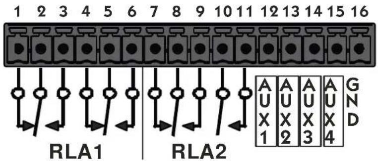
Outputs
There are two outputs available:
RLA1 - this is a two pole changeover (DPDT) relay rated at 1A 30V DC or 125V AC.
RLA2 – this is a two pole relay with one changeover contact and one normally open contact, both rated at 1A 30V DC or 125V AC. Note that RLA2 is driven in common with the DUMP light, so if its source is changed from the default SAFE value, the DUMP light will not operate as described in this manual.
These outputs can be configured by using normal configuration mode operations to get to SREM and then selecting RLA1 or RLA2 as appropriate. The relays may be activated as below:
OFF never
ON always (useful for testing)
BYP when bypassed
CNF during configuration mode
UFS when WAIT FOR SAFE is active
URE when WAIT AND EXIT is active
REB when REBUILD-ing
RMP0 when RAMP-ing TO ZERO
SAFE when the delay is greater than the configured safe time
SNEZ when SNEEZE is active
DUMP when the DUMP button is pressed
LIVE when the delay is at 0.00
STAT when the delay value is stable and non-zero
PANC when in panic mode
FULL when the delay is at maximum
MUTE when the output is muted
SBRK during a Station Break Insert operation (see below)
The default value for RLA1 is DUMP and for RLA2 is SAFE.
Appendix A BD600+ Basic Remote Control
Inputs
There are four input controls, AUX1 to AUX4. They should be actuated by shorting them to GND. Do not apply a voltage to these inputs as it may damage the unit. These inputs may be configured to replace existing push buttons or to provide other functions that cannot be achieved with the normal front panel controls. Note that most of these inputs do not function when the unit is bypassed.
OFF the input is disabled
BYP same as BYPASS button
CNF same as CONFIG button
UFS same as WAIT FOR SAFE button
URE same as WAIT AND EXIT button
REB same as REBUILD button
RMP0 same as RAMP TO ZERO button
SNEZ same as SNEEZE button
DUMP same as DUMP button
PANC same as PANIC button
LIVE go immediately to zero delay. May cause a discontinuity in output audio
STAT go to static mode - cancel any REBUILD or RAMP TO ZERO operation
FULL go at once to maximum delay. May cause a discontinuity in output audio
MUTE mute the audio outputs while active
SBRK see page 35 for information on the Station Break Insert feature
RTB Ramp To Bypass - RAMP TO ZERO, then BYPASS the unit
O-R DUMP, then REBUILD
W - R if live, go to REBUILD else WAIT AND EXIT
O-R if live, go to REBUILD else RAMP TO ZERO
ONE make jingle ONE the current jingle
TWO make jingle TWO the current jingle
THRE make jingle THREE the current jingle
FOUR make jingle FOUR the current jingle
The factory defaults are:
AUX1-BYP
AUX2 - DUMP
AUX3 - SMEZ
AUX4 - PANC
A simple circuit for triggering DUMP:
With factory default settings, connect your push-button between pins 13 and 16.
Station Break Insert
This remote-only function mutes the output for 4.0 seconds (variable on BD600E+) while continuing to enter input audio into the delay – typically, the RLA1 or RLA2 outputs will be configured to trigger an external cart machine to seamlessly insert a Station Identification Break or other jingle into the program material without loss of input audio which can then be time-compressed to make room for it. To use this feature successfully on a BD600+, the current delay value must be 4 or more seconds below the maximum. On completion, the delay value will be 4.0 seconds longer than when it was triggered, or the configured OPLAY value, whichever is shorter.
On BD600E+, a Station Break Insert may be programmed to JING, which will cause the current selected jingle to be played directly from the CF card rather than requiring an external cart machine and mixer. This jingle may in practice be a Station Break, a promotion or a commercial.
See Insert Operations below for more information.
Appendix B BD600E+ Extended Remote Control

The BD600E+ with the Extended Remote Control feature has 16 configurable parallel inputs and 16 configurable parallel outputs, as well as an RS232 (serial) delay input and output.
Extended Remote Connectors
The extended remote connectors are DB25 for parallel input and output, and DB9 for serial input and output. See Appendix E for connection and electrical information.
Parallel Outputs
There are 16 identical parallel outputs. These may be used as status (tally) outputs to show the operational state of the unit, or they may be fed with a version of the corresponding input delayed by the current delay amount.
These outputs can be configured by using normal configuration mode operations to get to SEXT and then selecting OUT1 or OUT2 etc as appropriate. The outputs may be activated as below:
OFF never
ON always (useful for testing)
OLIN a delayed version of the corresponding parallel input
BYP when bypassed
CNF during configuration mode
WFS when WAIT FOR SAFE is active
WRE when WAIT AND EXIT is active
REB when REBUILD-ing
RMPO when RAMP-ing TO ZERO
SAFE when the delay is greater than the configured safe time
SNEZ when SNEEZE is active
DUMP when the DUMP button is pressed
LIVE when the delay is at 0.00
STAT when the delay value is stable and non-zero
PRNC when in panic mode
FULL when the delay is at maximum
MUTE when the output is muted
SBRK during a Station Break Insert operation (see page 35)
TIM1 when the delay is greater than the configured TIM1 value
TIM2 when the delay is greater than the configured TIM2 value
INS when an Insert operation is active (see Insert Operations below)
JBAD the selected jingle is bad or absent or the card is not present. Also activated when the jingle is in use or being prepared for use.
MAX the current delay is greater than the maximum configured value (see Insert Operations below)
TOP the current delay is at the maximum allowable value (see Insert Operations below)
UNLK when the digital audio input is unlocked
Appendix B BD600E+ Extended Remote Control
Factory default values for Parallel Outputs
The default values for OUT1-16 are as follows (note that prior to V1.4 OUT3-16 defaulted to OFF):
OUT1 DUMP
OUT2 SAFE
OUT3 BYP
OUT4 SNEZ
OUT5 WFS
OUT6 WRE
OUT7 REB
OUT8 RTO
OUT9 LIVE
OUT10 STAT
OUT11 FULL
OUT12 MUTE
OUT13 SBR
OUT14 INSERT
OUT15 JBRD
OUT16 TIMI
Appendix B BD600E+ Extended Remote Control
Parallel Inputs
There are 16 input controls, IN 1 to IN16. These inputs are opto-isolated and can be driven with a voltage of either polarity between 5 and 25 volts. They may be configured to remotely duplicate existing push buttons or to provide other functions that cannot be achieved with the normal front panel controls. These inputs may also be configured to feed the corresponding outputs, delayed by the length of the audio delay. It is possible, but not always wise, to combine the delay and control functions. Note that most of these inputs do not function when the unit is bypassed.
The activity light on the rear panel will light briefly if any of these inputs change.
OFF the control input is disabled. It can still be used as a delay source.
BYP same as BYPASS button
CNF same as CONFIG button
UFS same as WAIT FOR SAFE button
URE same as WAIT AND EXIT button
REB same as REBUILD button
RMP0 same as RAMP TO ZERO button
SNEZ same as SNEEZE button
DUMP same as DUMP button
PRNC same as PANIC button
LIVE go immediately to zero delay. May cause a discontinuity in output audio
STAT go to static mode - cancel any REBUILD or RAMP TO ZERO operation
FULL go at once to maximum delay. May cause a discontinuity in output audio
RUTE mute the audio outputs while active
SBRK see page 35 for information on the Station Break Insert feature
RT8 Ramp To Bypass - RAMP TO ZERO, then BYPASS the unit
D-R DUMP, then REBUILD
-R if live, go to REBUILD else WAIT AND EXIT
O-R if live, go to REBUILD else RAMP TO ZERO
ONE make jingle ONE the current jingle
TWO make jingle TWO the current jingle
THRE make jingle THREE the current jingle
FOUR make jingle FOUR the current jingle
INS go to insert mode while active (see Insert Operations below)
The default values for IN1-16 are as follows (note that prior to V1.4 IN5-16 defaulted to OFF):
IN1 BYP
IN8 RTO
IN15 ONE
IN2 DUMP
IN9 LIVE
IN16 TWO
IN3 SNEZ
IN10 STAT
IN4 PANC
IN11 FULL
IN5 WFS
IN12 RUTE
IN6 WRE
IN13 SBR
IN7 REB
IN14 INS
Appendix B BD600E+ Extended Remote Control
Control Signal Delay
If a parallel output is configured to DLIN, it will output the corresponding input delayed by the current audio delay, whether Broadcast Delay or MPD. This is useful for synchronization of control signals with the delayed audio.
In this case, the corresponding input will normally be set to OFF to prevent it also controlling a BD600+ function.
Insert Operations
The BD600E+ supports an Insert feature, allowing a variable length announcement, commercial or station break info to be inserted into a delayed program which can then be automatically time-compressed to make room for it. This operation is similar to the Station Break Insert described on page 35, with the difference that the length of the insert is determined by an external input. During the Insert operation playback of delayed audio ceases and the output of the BD600+ is muted while input audio continues to be fed into the delay. Typically, one of the remote outputs is used to operate a relay to externally mix the inserted audio - alternately this operation may be performed manually. Once the insert is complete, the BD600+ reverts to normal broadcast mode and continues the playback of the delayed audio.
The following applies to both Insert and Station Break operations.
Dump or sneeze operations may be performed while Insert or Station Break operations are active if the BD600+ input is being monitored.
An Insert or Station Break (SBR) operation is real time by nature, so that inserted audio is heard immediately, while the input to the BD600+ will be delayed according to the current delay value, which will be increased by the length of the insert. During Insert and SBR operations the current delay is allowed to exceed the configured Maximum Delay OLAY if this is less than the maximum allowable amount (80 seconds). At the end of a SBR or Insert operation, if the current delay is greater than OLAY, the unit will go into a Ramp To Zero mode until the OLAY value is reached.
As an example, suppose that OLAY is set to 20 seconds, and that the current delay is 10 seconds. A 30 second SBR or Insert is performed. During this operation the live input audio will be stored in the unit and the delay value will increase at real time until the end of the operation when it will read 40 seconds (10 + 30). The unit will then start to ramp the delay downwards until 20 seconds (OLAY) is reached when the delay value will become static. The result is that the input audio is time-compressed to make room for the SBR or Insert. Once the unit has ramped down to 20 seconds it is back in normal Broadcast Delay mode. If one of OUT1-16 is configured to >MAX, this will be active while the delay value is above the configured OLAY value.
IMPORTANT – if an Insert or Station Break operation causes the current delay value to reach the maximum value of 80 seconds, all new input audio will be lost until the delay value is reduced – when the delay is full there is nowhere to save the input audio. For this reason it is recommended that the sum of the configured OLY value and the longest possible Insert or SBR not exceed 80 seconds. If one of OUT1-16 is configured to TOP, this will give a warning that input audio is being lost, but this event should be strenuously avoided.
Insert or SBR operations should be considered live performances and testing and rehearsal are highly recommended before on air use.
Appendix B BD600E+ Extended Remote Control
Serial input and output
The BD600E+ can delay a single RS232 channel by the same amount of time as the audio delay. This allows control signals or time indication to be synchronized with the output audio. The baud rate, number of bits and parity may be configured. The number of stop bits sent is fixed at two. Typically the source signal will be connected to the RS232 delayed input, a 9 pin female PC type connector, and the delayed RS232 will be supplied by the corresponding 9 pin male connector. A LED indicator on the back panel indicates activity – it is lit when the delay contains RS232 data.
The serial delay has a capacity of over 80000 characters. This means that it can handle continuous transmission at 9600 baud with the full 80 seconds of delay, but can be overwhelmed at higher rates. Typically this feature will not be used with high bandwidth data as normal time or control signals involve only a few characters per second.
To be sure that the delay is not overfilled, the serial data should be limited to 1000 characters per second at the 80 second full delay, and proportionally more at lower maximum delay values. The unit can accept full speed transmissions at any of its supported baud rates – the limit described is the maximum number of stored characters at any given time.
Note that neither the RS232 handshake signals are not delayed, nor any returned data (negative delay is difficult, even for Eventide).
One possible source of confusion is that during a Wait for Safe operation no data will emerge from the delay. This is normal and correct - during this operation the delay setting is increasing at the rate of one second per second – meaning that no data can reach the end of the delay before the delay time is increased. Once the Wait for Safe operation has finished, the data in the delay will appear.
After V1.4, the serial delay will be set to zero when the unit is bypassed. Any data that is in the delay will be immediately output when the unit enters bypass – it will not be lost.
Appendix C RS232 Remote Control
A BD600+ can be completely configured and operated from a personal computer or user-supplied custom control system. The female 9 pin RS232 connector on the rear panel is the mate for the male COM port on a typical desktop computer. The BD600+ operates as Data Communication Equipment (DCE) - the same as a modem. A straight through (pin 1 connected to pin 1, etc.) cable may be used to connect the BD600+ to a unit operating as Data Terminal Equipment (DTE), such as a personal computer.
The default characteristics of the RS232 connection are 9600 baud, 8 bits, 1 stop bit and no parity (9600, 8, 1, none). The BAUD rate may be changed via the configuration system.
The following table is the pin number, label, and direction relative to the BD600+. The label is the same as used by the terminal or PC that will be connected to the BD600+. Since the BD600+ is DCE, the labels and direction are opposite in meaning to those of the DTE definitions.
Pin 1 DCD (out)
Pin 2 RxData (out)
Pin 3 TxData (in)
Pin 4 DTR (in)
Pin 5 Gnd
Pin 6 DSR (out)
Pin 7 RTS (in)
Pin 8 CTS (out)
Pin 9 RI (out)
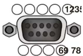
The BD600+ does not require the hardware control lines. Only RxData, TxData and Gnd are necessary.
The BD600+ only sends messages as a response to a poll from a host computer. The host computer must not send a message unless it has received a > character (hex 3E) or unless it has not heard from the BD600+ in 100mS . An overflow or bad message will be answered with a E> (hex 45, 3E).
The right-hand display bar segment will flash when receiving RS232 information. A terminal or PC terminal emulator can usefully be used to debug and demonstrate command sequences.
Protocol
The following page has a list of mostly single byte commands which are available to the host computer. The table lists the response generated by the BD600+. All commands will generate a response:
!> indicates command processed with no other data returned
X> indicates command not valid at this time
E> indicates serial port error or unrecognized command
Redundant commands will be answered with a !> or X> as appropriate. End of sneeze and mute will put the unit back in the mode it was in before the sneeze or mute started. All transmitted and received bytes are ASCII characters between '0' and '-' or 30 hex and 5F hex, as well as line feed (0A hex) and carriage return (0D hex).
Protocol notes
The unit is allowed to send an error message (E> or X>) at any time. Any interrupted message is terminated when the error message is sent, so the > character will be permission for the external device to send a new command. Command letters may be upper case or lower case. The command set is based on that of the Eventide BD500 with necessary differences.
RS232 Command Set
| 0 requests static at 0 delay | puts the unit in-line. If the unit was in BYPASS and the RUN variable specifies MPD or MPD-4, MPD mode will be entered, using the selected delay. Otherwise the unit will enter profanity delay mode at zero delay (live). |
| 1 increments MPD digit | note: MPD must be entered via configuration change to the RUN mode parameter. |
| 2 decrements MPD digit | |
| 3 selects MPD digit | |
| 5 starts mute | use the K command to un-mute. Works in MPD and profanity delay modes. The system will continue whatever it was doing before, but the output will be silent. Mute will be cancelled on entering BYPASS. |
| 4 not used | |
| 6 initiates or cancels station break insert see page 35 for information on the Station Break Insert feature. | |
| 7 initiates ramp to bypass | performs ramp to zero and then automatically switches to bypass. |
| 8 initiates wait for bypass | performs wait and exit and then automatically switches to bypass. |
| 9 not used | |
| @ go to MPD initial character must be followed within 1 second by one of 0 to 4 - will enter MPD mode using either current MPD value (value 0), or MPD value 1 to 4 (value 1,2,3 or 4). This will last until the next bypass, after which the unit will return to its configured mode. | |
| A initiates wait and exit | |
| B switches to bypass mode | |
| C requests config values shows the current settings of each of the config values. This long response includes multiple records, each consisting of a 4 byte config variable name, followed by an ASCII equal sign (=), followed by a 4 byte config value, followed by hex 0D,0A (carriage return, line feed). The last record will be followed by a >. None of the 4 byte values contain >. The records correspond to configuration variables described in Chapter 3 and consist of ASCII characters of the set 0 through 9, A through Z, space and dash. Records will be padded with trailing spaces where necessary to bring them up to 4 bytes. | |
| D performs a dump | note: this command will NOT drive RLA1 or RLA2, even if configured for DUMP. |
| E entire config table dump entire config table with all variables and all available values. This long response includes multiple records, each consisting of a 4 byte config variable name, followed by an ASCII equal sign (=), followed by one or more 4 byte strings, each containing config values, separated by spaces, followed by a space and then hex 0D,0A (carriage return, line feed). The last record will be followed by a >. None of the 4 byte values contain >. The records correspond to configuration variables described in Chapter 3 and consist of ASCII characters of the set 0 through 9, A through Z, space and dash. Records will be padded with trailing spaces where necessary to bring them up to 4 bytes. Note that the REB values will depend on the current OLAY value. | |
| F go to static at full delay | if the RUN variable does not specify MPD, the unit goes to in-line, static and at full delay. |
RS232 Command Set
G go to next config variable steps to next config variable. Responds with normal !>. Use X to request current config variable name and value. See also C, E, N, Q, V, X, and Y commands.
H go to static at current delay cancels a rebuild or ramp to zero.
I enter panic mode
J set delay followed by a numerical delay value terminated by a space or
more than one second is allowed to elapse between characters, and no characters apart from 0-9 and decimal point and space characters are allowed. If the unit is in MPD mode this command sets the MPD time, otherwise the delay cannot exceed the current OLY value.
When not in MPD mode, the OLY value can instead be temporarily set by this
command by terminating the value by an asterisk, e.g. J57.5*. This will last until the unit next starts or enters bypass, at which point the OLY value will be restored to the configured value.
K ends a sneeze or mute or station break
L requests levels three-character response is left channel level followed by right channel level
and terminated with >. Levels are reported using one digit ASCII hex of range 0 through 9, and A. Example: 25> is left channel level of 2, right channel of 5.
M requests mode response is three characters of the form m!> where m is the current mode.
Modes are A
note: zero delay and maximum delay are not modes; if the unit reaches maxi-
mum delay while in rebuild, it switches to static mode, while if it reaches zero delay while in ramp to zero, it switches to live mode.
N next config value sets the current config variable to the next value. When the maximum value is
reached, the next will be the minimum. Responds with normal "!>", Can only be used in bypass mode. Use X to request current config variable name and value. See also G command.
P requests MPD delay value response is 8-digit (including decimal point) ASCII value of delay in millisec-
onds, followed by position indicator (1, 2, 3, 4, 5 or 6), followed by >. Note: This does not change the mode to MPD. Example: if delay is 1.1 seconds and the 4^th digit is selected, the response will be “1100.0004>”.
Q resets config stepping points at start of configuration mode. Used with C, E, G, N and V, X, and Y
commands to make configuration changes to the BD600+.
R initiates rebuild
S starts a sneeze see K command for end-sneeze.
T requests current delay response is 4-digit decimal ASCII value of delay in 10s of milliseconds, fol-
lowed by >. The BD600+ can be configured to automatically send delay values whenever they change by use of the SEND configuration variable.
U requests current delay as hex sends delay amount in 10s of milliseconds as hexadecimal using 4 chars of
ASCII hex followed by H>.
V Eventide Factory Defaults sets factory defaults for all config variables (except baud rate). System must be
in bypass.
RS232 Command Set
W initiates wait for safe note: when the unit reaches safe, it will switch to rebuild mode.
X examine config gives current config variable and value. Responds with a 10-character message consisting of a four-character config variable identifier, an ASCII equal sign (=), the four-character value of the config variable, and a >. See G, N and Q.
Y first value sets the current config variable to the first value. Can only be used in bypass mode. Useful for making automated configuration changes. See C, E, G, N, Q, V and X commands.
Z initiates ramp to zero
RS-232 Command Examples and Tables
This section offers organizational information and help information for using RS-232 commands.
Profanity Delay Commands
These are the profanity delay commands. Note that some rarely used commands are left out of this section.
L requests levels
M requests mode
T requests current delay
U requests current delay/hex
0 go to static at 0 delay
H go to static at current delay
B switches to bypass mode
W initiates wait for safe
A initiates wait and exit
Z initiates ramp to zero
R initiates rebuild
S starts a sneeze
K ends a sneeze
D performs a dump
Micro Precision Delay Commands
These are the fixed delay commands.
L requests levels
B switches to bypass mode
0 switches from bypass to in-line
1 increments MPD digit
2 decrements MPD digit
3 selects MPD digit
P requests MPD delay value
The RS232 commands allow the front panel of the BD600+ to be completely replicated in function (and in form) by a remote device. A computer with a terminal emulator may use these commands to prove that all of the information and control are available. Use the T, M and P commands to watch modes and delays change as commands are issued.
Configuration Mode Commands
The RS232 configuration commands step through the configuration variables in much the same way the front panel does. Use the G command to step to the next variable. Use the N command to step through values for a single variable.
Most values will be used by the BD600+ immediately after they are changed, so care must be taken not to change those that may cause undesirable artifacts on air.
M requests mode
B switches to bypass mode
0 switches from bypass to in-line
C dump values for all config variables
E dump possible values for all variables
G go to next config variable
N next value for this variable
Q back to first variable
V Eventide Factory Defaults
X examine current variable
Y first value for this variable
Example configuration operations
Note that you must wait for a prompt before sending each character.
To change the rebuild rate from whatever it happens to be to 240, you can send
QGGGGGGGGYNNNNN.
(Spaces are shown to increase readability and would not be sent.) This sequence says: go to first variable, then step through the variables to the REB variable, then set it to the first value, then step through to the 6th value which is 240 (for an 8.0 seconds OLAY value).
In order to change the full delay amount, the unit has to be placed into bypass. This sequence will change the maximum delay to 4.0 seconds and put the unit back in-line.
Q G G G G G G G Y N B 0.
Note that if you issue the B command while the unit is already bypassed, you will get an error message. Your sequence may expect the error message and ignore it.
Appendix D Diagnostics
Start-up Switches
The BD600+ has operations which are used in the factory to prepare the unit to be shipped. Each operation is performed by turning on the unit while holding down a button until the version number message goes away. Some of them may post a “do you want to..” type message, with the WAIT AND EXIT button blinking to indicate “yes” and the REBUILD button lit steadily to indicate “no.”
Restore Factory Defaults - PANIC button
This function restores all configuration values to the factory defaults. In the event of serious system malfeasance, this function should be tried, and if it does not restore normal behavior, do the following to clear memory.
Clear all Memory - RAMP TO ZERO button
This function clears all memory and returns the unit to the state at which it left the factory.
Perform Production Self-Test - SNEEZE button
This function goes into a series of self tests. Many of these tests cannot pass unless loop-back connectors are installed on audio and control connectors. These tests should only be run under instruction from Eventide as some of them can erase internal programs.
Other Functions
The remaining front panel keys are unused at this time or are reserved for factory purposes.
Appendix E Extended Remote Connections
Parallel Outputs
The parallel outputs are of the open-collector type, meaning that when active, the output is pulled to ground by a transistor. A 5V supply capable of a maximum of 500mA is available on the connector, along with a clamp input that may be useful when driving relays.
The outputs can handle a maximum voltage of +50V DC in the off state and a maximum current of 0.5A per output in the on state (0.2A if all outputs driven) – operation above these limits will damage the output circuitry. It is recommended that suitable relays be used to handle currents and voltages above 100mA/25V to protect the unit from possible damage or overheating.
| (1) Chassis Ground | (6) Ground | (11) Ground | (16) Out 10 | (21) Out 14 |
| (2) Out 1 | (7) Out 5 | (12) Ground | (17) Out 11 | (22) Out 15 |
| (3) Out 2 | (8) Out 6 | (13) +5V 0.5A | (18) Out 12 | (23) Out 16 |
| (4) Out 3 | (9) Out 7 | (14) Ground | (19) Ground | (24) Ground |
| (5) Out 4 | (10) Out 8 | (15) Out 9 | (20) Out 13 | (25) Clamp |
Notes
- None of the ground connections may be used as a safety ground – they are rated for low current DC operation only.
- The Chassis Ground connection (1) may be used as a screen connection. It should not be connected otherwise.
- If the +5V 0.5A supply (13) is used, output loads need only be connected from here to each output. These would typically be LED indicators with suitable series resistors or small 5V relays.
- If an external power source is used, its -ve side should be connected to ground (6,11,12,14,19,24) and its +ve side be used as the power source. Output loads should be connected between the output signal (Out 1, etc) and the power source. The grounds are connected together inside the unit - for low currents only one need be used.
- The clamp signal (25) is the common cathode connection for clamping diodes connected to each output. If this is connected to the power source, it will prevent the voltage on each output from exceeding the power voltage. This would mainly be used for back-emf protection when driving relays or other inductive loads.
- The driver chips for these outputs are socketed so that they can be easily changed if damaged – U110 handles OUT1-4, U112 handles Out5-11, U111 handles Out12-16.
Appendix E Extended Remote Connections
Parallel Inputs
The parallel inputs are opto-isolated and bipolar, meaning that they may be driven by a positive or a negative voltage. This voltage may range between 5 and 25 volts.
One side of each input is commoned in groups of 4. By default, all these groups of common connections are tied together. This may be changed by the use of internal jumpers P100-103 – if these are all removed the inputs will be isolated from ground and from the other groups of 4.
| (1) Chassis Ground | (14) Signal Ground |
| (2) In 1 | (15) In 9 |
| (3) In 2 | (16) In 10 |
| (4) In 3 | (17) In 11 |
| (5) In 4 | (18) In 12 |
| (6) Common 1-4 | (19) Common 9-12 |
| (7) In 5 | (20) In 13 |
| (8) In 6 | (21) In 14 |
| (9) In 7 | (22) In 15 |
| (10) In 8 | (23) In 16 |
| (11) Common 5-8 | (24) Common 13-16 |
| (12) no connection | (25) no connection |
| (13) +5V 0.5A |
Notes
- None of the ground or common connections may be used as a safety ground – they are rated for low current DC operation only.
- The Chassis Ground connection (1) may be used as a cable screen connection. It should not be connected otherwise.
A simple circuit for triggering DUMP:
With factory default settings, connect your push-button between pins 3 and 13, and connect pins 6 and 14 together.
Appendix E Extended Remote Connections
The BD600E+ serial input is wired to connect to a PC serial output, while its output is wired to look like a PC serial output. RxData and the handshake lines (CTS, RTS etc) are not delayed or used by the BD600+ and need not be connected in most cases – only TxData and Gnd will be required for many applications..
Serial Delay Inputs
Pin 1 DCD (out)
Pin 2 RxData (out)
Pin 3 TxData (in)
Pin 4 no connection
Pin 5 Gnd
Pin 6 DSR (out)
Pin 7 RTS (in)
Pin 8 CTS (out)
Pin 9 RI (out)
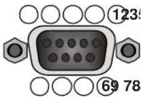
Serial Delay Outputs
Pin 1 DCD (in)
Pin 2 RxData (in)
Pin 3 TxData (out)
Pin 4 DTR (out)
Pin 5 Gnd
Pin 6 no connection
Pin 7 RTS (out)
Pin 8 CTS (in)
Pin 9 RI (in)
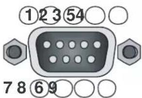
Appendix F BD600W+ WheatNet-IP
WheatNet-IP is a product of the Wheatstone Corporation, which allows multiple pieces of audio equipment to pass audio and control signals over a Gigabit Ethernet network. The BD600W+can be connected to a WheatNet-IP network, usually as a slave of a "Blade." It should be noted that most networking issues are beyond the scope of this manual, and should be addressed directly to Wheatstone Technical Support.
Connecting the BD600W+to a WheatNet-IP Network
To add a BD600W+to a WheatNet-IP network, you will need at least one Wheatstone Blade attached to the network. This is because the BD600W+acts as a “slave” to the Blade. Before connecting the BD600W+you will need its IP (Internet Protocol) address – this defaults to 192.168.87.239, and is displayed during the BD600+W’s startup sequence. The system can be configured by using Wheatstone’s WheatNet-IP Navigator application, shown below.
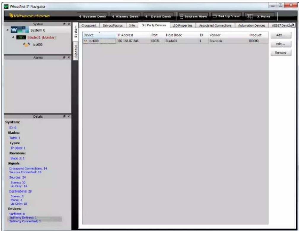
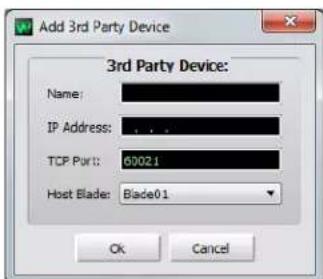
First connect your BD600W+to the WheatNet-IP system using a suitable network cable – this will probably connect to a Gigabit switch which is part of your network.
The BD600W+is viewed as a “3 ^rd Party Device” - to add it to the system, click on the “3 ^rd Party Devices” tab. This will show the window above. Click the “Add…” button, and enter a suitable name and the BD600+W’s IP address.
Leave the "TCP Port" and "Host Blade" values alone.
Appendix F BD600W+ WheatNet-IP
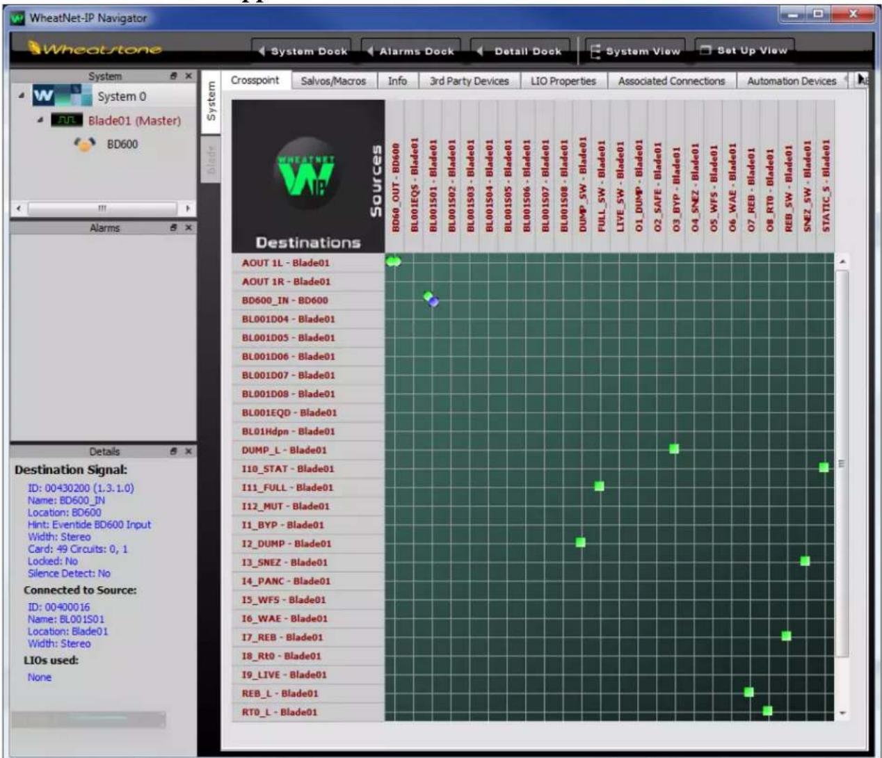
Connecting Audio between the BD600W+and WheatNet-IP
The BD600+W's audio inputs and outputs will appear on the Navigator Crosspoint screen, shown above. They can be identified by right-clicking on the Source or Destinations list and choosing Show/Name-Location. The BD600+ sends a stereo output and receives a stereo input from the network, shown as Location BD600+ (assuming BD600+ was the name given on the "Third Party Devices" tab).
Note that the BD600+ audio output is always sent to the network, while its audio input is only received from the network when INPT is set to WINET. In this case, SYNC can only be set to DIG, as the BD600+ must run at the same sample rate as the network.
Appendix F BD600W+ WheatNet-IP
Connecting Control Signals between the BD600W+and WheatNet-IP
The BD600W+can receive 16 control signals from the network, and send 16 statuses to it. The meaning of these to the BD600W+are configured under 5EXT, Extended Remote Control Parameters. In this respect, the BD600W+is similar to the BD600E+ - the difference being that the BD600+W's control and statuses are logical network signals, rather than physical rear panel connections.
In WheatNet terminology, these logical control and status signals are known as LIOs (Logic Input or Output). BD600+ LIOs can be studied by selecting the Blade to which the BD600+ is attached and then clicking on the Sources or Destinations tab as appropriate. Click Add to create a new LIO.
The available BD600+ LIOs are shown in the Free Resources window, while the existing signals are shown in the Source (Destination) window. Note that both BD600+ and Blade LIOs are shown with the Blade as the Location. The only way to confirm the actual BD600+ LIOs is to look at the LIO Info tab, which will list the BD600+ LIOs, showing their signal names and other info. The reader should study the WheatNet-IP documentation for more information on configuring LIOs.
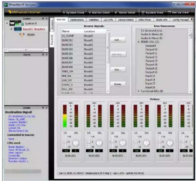
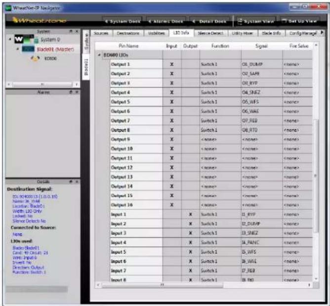
WheatNet related error messages
If the BD600W+shows an unlocked indication when INPT is set to UNET, this indicates a hardware problem in the BD600W+. This will be shown by flashing horizontal bars in Bypass, or a NO LOCK indication otherwise. The BD600+W's input will act as configured under FALLBACK.
A message saying NO UNET ROUTING means that either the BD600+ audio input or output is not connected to another signal. This may be deliberate.
A message saying NO UNET CABLE means that the BD600W+is not connected to the WheatNet-IP network. This may be due to cabling issues or hardware problems.
If either the IP address is not displayed at startup, or IMPT cannot be set to UNET, this indicates a hardware problem in the BD600W+.
Appendix F BD600W+ WheatNet-IP
Changing the IP Address
The default IP (Internet Protocol) address for the BD600W+is 192.168.87.239. You may need to change this value if it clashes with another piece of connected equipment, for example if you have more than one BD600+W. The IP address for any piece of equipment must be unique - if you need to change it, obtain a suitable value from your Network Administrator.
To change the IP address you will need an internet connection to the BD600W+and a software application that can log onto it using the Telnet protocol. Again, your Network Administrator can assist. You will need the current IP address to log on to it – this is displayed at BD600W+power up.
When the connection is made, you will see:
Wheatstone Telnet Server
Copyright 2012, Wheatstone Corp.
Ctrl-D - Exit
Ctrl-E - Toggle Echo
Please log in...
Username:
Enter “wheatstone” when prompted for Username, followed by the Enter key, and when prompted for Password, hit the Enter key without any text to enter a blank password. At this point, you should see something like:
WheatNet IP Eventide BD600+ Software Version 1.4.9
Built Jun 15 2015 at 10:58:25
Booter ver:0.0 type:000003 dip:0000
FPGA ver:000A0002
Device Type: Eventide
For a command menu, type "help"
->
Once you see this, enter the following at the “->” prompt:
ip
Where:
As an example, to set the above IP address, the command to enter is:
ip 192.168.87.240 255.255.255.0 192.168.87.1
Once the command is recognized, it will prompt you to reboot:
Reboot required to implement changes
Appendix G - Installing Windows Drivers
Installing Windows Drivers
It is only necessary to install this driver when using USB on Windows 7 – later OS versions do not require it.
With the BD600+ powered up and connected to your computer by USB, bring up “Control Panel”, then “Device Manager”.
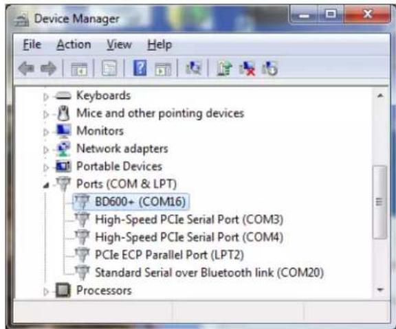
Look under "Ports (COM & LPT). If BD600+ is visible as above, this procedure is unnecessary.
Otherwise, if "BD600+" is not visible, look for "Unknown Device" under "Other Devices."
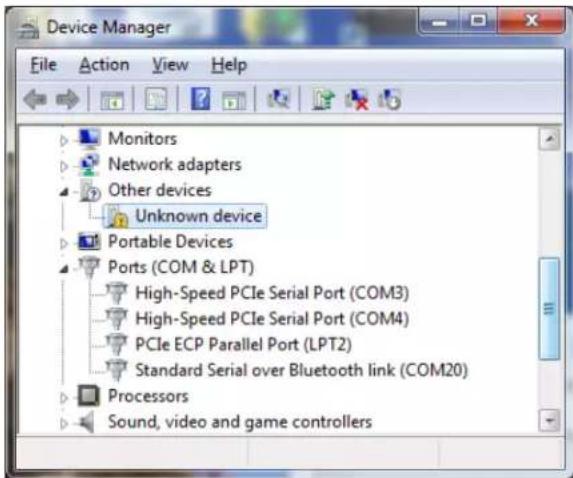
Right-click on "Unknown Device" and select "Update Driver Software."
Appendix G - Installing Windows Drivers
Select "Browse my computer....." You will see the following dialog.
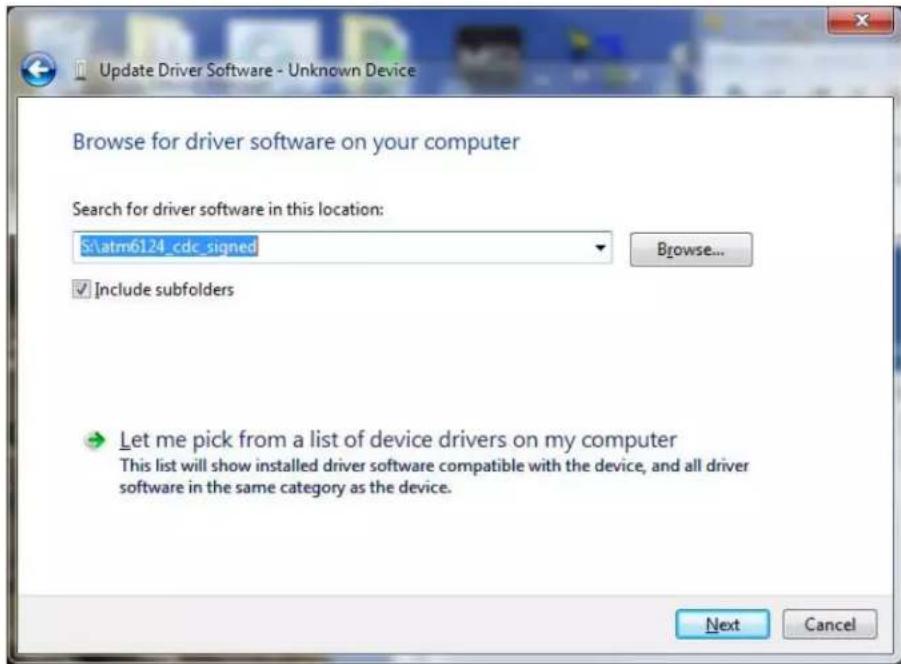
Hit the “Browse” button, and locate and select the CD drive containing the “BD600+ Install Software” CD. Hit “Next”. If you see a “Windows Security” window, click on “Install this driver....”
You should now see a “Windows has successfully updated....” Window. Hit “Close.”
Specifications
Physical:
Size inches 1.75h x 19w x 10.5d
Size centimeters 4.4h x 48.3w x 26.7d
Weight 6 lbs. net
Shipping weight 10 lbs
Power 50 watts, 100-240V AC 50/60Hz
Fuse 4-Amp 250V AC Fast Blow on internal power supply unit
AES/EBU Digital inputs/outputs:
Connector XLR
Sample Rate 32-50kHz, 24 bits/sample
Analog inputs/outputs:
Connector XLR, pin 2 hot, true differential balanced +4dBm nominal, +26dBm max
Sample Rate 44.1, 48kHz, 24 bit/sample
Frequency Response 20Hz to 20kHz, + - 1dB at 48K sampling
Signal to Noise ratio >110dB, 'A' weighted
Dynamic Range >100dB
Distortion <.003% @ 1kHz, 1dB below clipping in stable delay state
Basic Rear Panel Control Signals:
Control Signals
Remote outputs relay contacts - 1A 30V DC, 125V AC maximum
Remote inputs closure to ground
Extended Remote Rear Panel Control Signals:
External Power Supply
Voltage maximum of 50v
Control Signals
Remote outputs sink a maximum of 500mA individually, or 200mA each with all outputs driven
Remote inputs bipolar opto-isolated - 3mA at 4.5v minimum, 25v max
These specifications are subject to change without notice or obligation.
Warranty Information
LIMITED WARRANTY
The above-identified Eventide unit covered by this warranty is built to exacting quality standards and should give years of trouble-free service. If you are experiencing problems which are not cleared up in this manual, your recourse is this warranty.
What the warranty does and does not cover
Eventide Inc. warrants the above-identified unit to be free from defects in workmanship and material under normal operation and service for a period of one year from the date of purchase, as detailed below. At our discretion within the warranty period, we may elect to repair or replace the defective unit. This means that if the unit fails under normal operation because of such defect, we will repair the defective unit at no charge for parts or labor. We also assume a limited responsibility for shipping charges, as detailed below.
The warranty does not extend beyond repair or replacement as stated herein and in no event will we be responsible for consequential or incidental damages caused by any defect, and such damages are specifically excluded from this warranty. Our sole obligation is to repair or replace the defective unit as described herein.
The warranty DOES NOT COVER any damage to the unit regardless of the cause of that damage. The unit is a complex piece of equipment that does not react well to being dropped, bounced, crushed, soaked or exposed to excessively high temperatures, voltages, electrostatic or electromagnetic fields. If the unit is damaged for these or similar causes, and the unit is deemed to be economically repairable, we will repair it and charge our normal rates.
The warranty DOES NOT COVER shipping damage, either to or from Eventide. If you receive a new unit from us in damaged condition, notify us and the carrier; we will arrange to file an insurance claim and either repair or exchange the unit.
If you receive a new unit from a dealer in damaged condition, notify the dealer and the carrier.
If we receive the unit from you with apparent shipping damage, we will notify you and the carrier. In this case, you must arrange to collect on any insurance held by you or your carrier. We will await your instructions as to how to proceed with the unit, but we will charge you for all repairs on damaged units.
Who is covered under the warranty
The warranty applies to the original purchaser of a new unit from Eventide or an Authorized Eventide Dealer. Demo units are also covered by this warranty under slightly different circumstances (see below). Units that are used, or have been used as part of a rental program, are not covered under any circumstances.
It is your responsibility to prove or to be able to prove that you have purchased the unit under circumstances which effect the warranty. A copy of your purchase invoice is normally necessary and sufficient for this.
If you have any questions about who is an Authorized Eventide Dealer, call us.
Units with the serial number plate defaced or removed will not be serviced or covered by this warranty.
When the warranty becomes effective
The one-year warranty period begins on the day the unit is purchased from an Authorized Eventide Dealer or, if the unit is drop-shipped from Eventide, on the day shipped, plus a reasonable allowance for shipping delays. This applies whether or not you return your warranty registration form.
When we receive a unit, this is how we determine whether it is under warranty:
- If the unit was shipped from our factory within the past calendar year, we assume that it is under warranty unless there is evidence to the contrary, such as its having been sold as used or rented, etc..
- If the unit was shipped from our factory more than a calendar year ago, we assume it is not under warranty unless:
a) There is a warranty registration form on file showing that it has been purchased within the past year under appropriate conditions.
b) You send a copy of your purchase invoice indicating warranty status along with the unit.
- If the unit was used as a demo, the warranty runs from the date that it was received by the dealer. The original purchaser gets the unexpired portion of that warranty.
When you send a unit for repair, you should indicate whether or not you believe it to be under warranty. If you do not say the unit is under warranty, we will charge you for the repair and we will not refund unless the charge was caused by an error on our part. If you believe the unit to be under warranty and you do say it is but we disagree, you will not incur any charges until the dispute is resolved.
Warranty Information
Reading the above, you can see that it is to your advantage to send in the warranty registration form when you purchase the unit. If we know who you are, we can send you updates and notifications, and advise you of our new products. It will also enable you to receive pre-shipment of certain parts.
Who performs warranty work
The only company authorized to perform work under this warranty is Eventide Inc., Little Ferry, New Jersey. While you are free to give personal authorization to anyone else (or to work on it yourself), we will not honor claims for payment for parts or labor from you or from third parties.
However, we and our dealers do try to be helpful in various ways:
- Our dealers will assist, usually without charge during the warranty period, in:
a) determining whether there is a problem requiring return to the factory, and
b) alleviating user error or interconnection problems that may be preventing the unit from operating to its full capability.
-
We are available for telephone consultation if the dealer is unable to assist.
-
If a part is found to be defective during the warranty period and you wish to replace it yourself, we will normally ship the part immediately at no charge, provided your warranty registration form is on file. We reserve the right to request that the defective part be returned to us.
Shipping within the 50 United States
You are responsible for getting the unit to our door at no cost to us. We cannot accept collect or COD shipments.
We will return the unit to you prepaid, at our expense, using an expeditious shipping method, normally United Parcel Service. In areas not served by UPS we will ship by US Mail.
If you are in a hurry and want us to use a premium shipping method (such as air express, next day air, etc.), be sure you tell us and agree to pay shipping charges collect. If you specify a method that does not permit collect or COD charges, remit sufficient funds to prepay shipping.
Shipping outside the 50 United States
If you purchased the unit from a dealer in your country, consult with the dealer before returning the unit.
If you wish to return the unit to us, please note the following:
-
The unit must be prepaid to our door. This means that you are responsible for all shipping charges, including customs brokerage and duties. When a unit is shipped to us it must be cleared through United States Customs by an authorized broker. You must make arrangements for this to be done. Normally, your freight forwarder has a branch in the United States which can handle this transaction. We can arrange to clear incoming shipments for you. If you want our assistance, you must notify us before shipping the unit for repair, giving full details of the shipment, and including a minimum of \$250.00 in US funds to cover the administrative and brokerage expenses. Any balance will be applied to the repair charges or refunded. If a balance is due to us, we will request a further prepayment.
-
All shipments will be returned to you collect. If this is impossible because of shipping regulations or money is due us, we will request prepayment from you for the appropriate amount.
-
All funds must be in \$US. Payment may be made by check drawn on any bank in the US, or by telegraphic funds transfer to our bank. If you send US currency, be sure that it is sent by a method you can trace, such as registered mail. If you wish to pay by Letter of Credit, be sure that it affords sufficient time for work to be performed and the L/C negotiated, and that it is free from restrictive conditions and documentation requirements.
-
We reserve the right to substitute freight carriers. Although we will attempt to honor your request for a specific carrier, it is frequently necessary to select a substitute because of difficulties in communication or scheduling.
This warranty gives you specific legal rights and you may also have other rights which vary from location to location.
(c) 1999, 2000, 2003 Eventide Inc
Index
AES/EBU ... 5, 6, 7, 9, 10, 17, 24, 29, 30, 32, 56
lock 10, 17, 29
Analog
input 7
output 7
balanced line 7,56
bar graph 3,4,8,16,20,41
baud rate 41,43
Button
BYPASS 8,9,14,19,21,35,38
CONFIG 3,9,19,21,35,38
DUMP .. 15, 16, 19, 24, 29, 31, 34, 35, 36, 38
PANIC.... 3, 15, 17, 22, 35, 38, 46
RAMP TO ZERO .... 4, 15, 19, 21, 35, 38, 46
REBUILD 3,4,15,35,38,46
SNEEZE ..... 4, 12, 14, 15, 21, 22, 35, 38, 46
WAIT AND EXIT .... 3, 9, 16, 19, 20, 21, 35, 38, 46
WAIT FOR SAFE.... 15, 35, 38
Button Function
BYPASS 3
CONFIG 3
DUMP 4,16
PANIC.... 3
RAMP TO ZERO 4
REBUILD 4
SNEEZE 4,16
WAIT AND EXIT 4
WAIT FOR SAFE.... 3
bypass
DSP 9,29
relay.... 14
Cancel
wait and exit 14
wait for safe.... 14
carriage return 41
Compact Flash ...... 1, 4, 12, 14, 15, 17, 30
Connector
1/4 inch jack 7
AES/EBU 6
Analog Input 6
Analog Output 6
Basic Remote 5,34,36,37
Delayed RS232 6
General Remote 6
RS232 6,26
Wordclock 6,9,32
XLR 6,7,9,56
display 3, 4, 8, 10, 14, 16, 17, 19, 20, 21, 22, 23, 29, 41
fallback 10,29
ground loop 7
jingle ..... 3, 12, 13, 14, 15, 17, 23, 24, 30, 35, 38
level
input 3,7,8,9
meters 3,8,9
line feed 41
Message
bad jingle 17,30
no lock 10, 17, 29
Panic
.WAV files 17
disabled 17
mute time 24
password 21, 23, 30
pitch change 10, 12
power switch 5,8
precision fixed delay 3,23
relay 1,3,5,7,14,15,29,34,56
Remote function
ramp to bypass 42
station break 42
wait for bypass 42
RS232 5,6,26,27,41,45
safe time .... 11, 15, 16, 24, 31, 34, 36
sample rate 9, 10, 17, 29, 30, 32
sample rate conversion 9,32
signal
clipping 8,9,56
overload 9
station break 35
sync 3,10,17,29
tape 11, 12
USB 5,17
version number 6,8,46
Wordclock 5,6,9,10,17,29,32
- Contents
- Chapter 1 Introducing the BD600 ....1
- Audio Connections 7
- Chapter 2 Operation....8
- Understanding BD600 Profanity Delay Functions....11
- Operating as a Profanity Delay....14
- Operation as a Micro Precision Fixed Delay 19
- Chapter 3 Configuration ....21
- Appendix A Basic Remote Control....34
- Appendix B Extended Remote Control 36
- Appendix C RS232 Remote Control.... 41
- Appendix D Diagnostics.... 46
- Appendix E Extended Remote Connections 47
- Appendix F Using BD600W with WheatNet-IP 50
- Installing Windows Drivers.... 54
- Specifications 56
- Warranty Information 57
- Chapter 1 Introducing the BD600+
- BD600+ Features:
- Additional BD600E+ Features:
- Additional BD600W+ Features
- Front Panel
- 1) BYPASS Button
- 2) Input Status
- 3) CONFIG Button
- 4) Level Meters
- 5) PANIC Button
- 6) WAIT FOR SAFE Button
- 7) WAIT AND EXIT Button
- 8) REBUILD Button
- 10) SNEEZE Button
- 11) Delay Amount Bar Graph
- 12) 4-Character Display
- 13) Card slot
- 14) DUMP Button
- Rear Panel
- 1) AC Power
- 2) Power Switch
- 3) USB Lamp
- 4) Basic Remote Connector
- 5) Wordclock in
- 6) Wordclock out
- Digital Audio Inputs and Outputs
- Analog Audio Inputs and Outputs
- Remote and other Connectors
- 14) Delayed RS232 in
- 15) Delayed RS232 out
- 16) Activity Indication
- 17) General Remote Input
- 18) General Remote Output
- 20) USB
- Chapter 2 Operation
- Analog
- Analog Outputs
- Analog Inputs
- Digital
- AES/EBU input, XLR
- AES/EBU output, XLR
- Audio Connection
- Installation
- Rack Mount
- Connect AC and Turn On Power Switch
- Level Meters
- Understanding BD600 Profanity Delay Functions
- Connect analog audio inputs
- Connect analog audio outputs
- Connect digital audio inputs
- Connect digital audio outputs
- Selecting the sample rate
- Notes and Warnings for AES/EBU Operation
- Using Wordclock
- Wordclock Termination
- REBUILD - Increase the delay gradually
- RAMP TO ZERO - Decrease the delay gradually
- WAIT FOR SAFE - Bring delay from live to 4 seconds quickly
- WAIT AND EXIT - Decrease the delay to 0 seconds quickly
- SNEEZE - Edit the delay before a bad noise happens
- DUMP - Edit the delay after a bad noise happens
- PANIC - lose all delayed audio and play a jingle while delay is rebuilt
- Insert or Station Break Insert – insert another audio source into the program material
- Operating as a Profanity Delay
- Modes
- Functions and Features
- Starting a Show Segment with REBUILD
- Starting a Show Segment with WAIT FOR SAFE
- Starting a Show Segment with PANIC
- Ending a Show Segment with RAMP TO ZERO
- Ending a Show Segment with WAIT AND EXIT
- DUMP Button
- In rebuild or ramp to zero
- In wait for safe
- In precision delay configuration mode
- In bypass, live, or wait and exit
- SNEEZE Button
- Delay Amount Display
- More Information on the PANIC feature
- Jingle files on the card
- When Jingles should not be used
- Operation as a Micro Precision Fixed Delay
- Controlling the Fixed Delay
- Notes on Precision Delay mode
- Chapter 3 Configuration
- Basic Operation Example
- Another Example
- Password Protection
- Restoring Factory Defaults
- Configuration Variables
- BYP Bypass mode
- DISP Display Digits
- DELAY Delay Length
- Dump Dump Amount
- FLBK Fallback
- FRAM MPD Frames Display
- INPT Input source
- JING Select current Jingle
- LOCK Lock Front Panel
- PANC Panic Mute Time
- PASS Password
- POWP Power-Up mode
- PUL5 Heartbeat Indicator
- REB Rebuild Time
- RUN Run mode
- SAFE Safe Time
- SBRK Station Break Duration (BD600E+, W only)
- SEND Delay Time Export Format
- SHOW Delay Display Type
- SRCE Source
- SYNC Sample Rate Source
- TMO Tempo Modification
- THRS Threshold Level Adjustment
- Appendix A BD600+ Basic Remote Control
- Basic Remote Connector
- REMOTE CONTROL
- Outputs
- Inputs
- A simple circuit for triggering DUMP:
- Station Break Insert
- Appendix B BD600E+ Extended Remote Control
- Extended Remote Connectors
- Parallel Outputs
- Factory default values for Parallel Outputs
- Parallel Inputs
- Control Signal Delay
- Insert Operations
- Serial input and output
- Appendix C RS232 Remote Control
- Protocol
- Protocol notes
- RS232 Command Set
- K ends a sneeze or mute or station break
- R initiates rebuild
- RS-232 Command Examples and Tables
- Profanity Delay Commands
- Micro Precision Delay Commands
- Configuration Mode Commands
- Example configuration operations
- Appendix D Diagnostics
- Start-up Switches
- Restore Factory Defaults - PANIC button
- Clear all Memory - RAMP TO ZERO button
- Perform Production Self-Test - SNEEZE button
- Other Functions
- Appendix E Extended Remote Connections
- Notes
- Serial Delay Inputs
- Serial Delay Outputs
- Appendix F BD600W+ WheatNet-IP
- Connecting the BD600W+to a WheatNet-IP Network
- Connecting Audio between the BD600W+and WheatNet-IP
- Connecting Control Signals between the BD600W+and WheatNet-IP
- WheatNet related error messages
- Changing the IP Address
- Appendix G - Installing Windows Drivers
- Installing Windows Drivers
- Specifications
- Physical:
- AES/EBU Digital inputs/outputs:
- Analog inputs/outputs:
- Basic Rear Panel Control Signals:
- Control Signals
- Extended Remote Rear Panel Control Signals:
- External Power Supply
- Warranty Information
- Index
Brand : EVENTIDE
Model : BD600E+
Category : Uncategorized