
H9000 Madi - Uncategorized EVENTIDE - Free user manual and instructions
Find the device manual for free H9000 Madi EVENTIDE in PDF.


| Product Type | Multi-channel Effects Processor with MADI Expansion |
| Brand | Eventide |
| Model | H9000 (with MADI card) |
| Dimensions (H x W x D) | 3.5 x 19 x 12.5 in (8.9 x 48.3 x 31.7 cm) – 2U rackmount |
| Weight | 14 lbs (6.4 kg) |
| Analog Audio I/O | 2 XLR inputs, 2 XLR outputs, 8 DB-25 inputs, 8 DB-25 outputs |
| Digital Audio I/O | AES3 (DB-25 & XLR), S/PDIF (RCA & Optical), ADAT (Optical), USB (16x16), Word Clock (BNC) |
| Expansion Slots | 3 slots (one populated with MADI card in this model) |
| Effects Processing | Up to 16 simultaneous algorithms across 4 FX chains, each chain can hold up to 4 algorithms in series/parallel |
| Control Interfaces | Front panel with color display and soft keys, Emote software (standalone and plug-in VST/AU/AAX), up to 4 foot pedals/switches, MIDI (DIN and USB) |
| Supported Sample Rates | 44.1, 48, 88.2, 96 kHz |
| USB Audio | 16 inputs and 16 outputs, works as Core Audio (macOS) or ASIO (Windows) device |
| Network Connectivity | Ethernet (wired) and optional Wi-Fi via USB adapter |
| Power Supply | Internal, standard AC power cable (100-240V, 50/60Hz) |
| Safety Certifications | FCC Class A, CE, RoHS |
| Warranty | Contact Eventide for details; warranty registration recommended |
| Included Accessories | USB cable, Wi-Fi adapter, power cable, rackmount screws, FAT32 USB drive, registration card |
Frequently Asked Questions - H9000 Madi EVENTIDE
User questions about H9000 Madi EVENTIDE
0 question about this device. Answer the ones you know or ask your own.
Ask a new question about this device
Download the instructions for your Uncategorized in PDF format for free! Find your manual H9000 Madi - EVENTIDE and take your electronic device back in hand. On this page are published all the documents necessary for the use of your device. H9000 Madi by EVENTIDE.
USER MANUAL H9000 Madi EVENTIDE
Copyright 2022, Eventide Inc
P/N: #141242 Version 2.0
Eventide and Harmonizer are registered trademarks of Eventide Inc.
Pro Tools, Pro Tools | HD, and DigiLink are trademarks of Avid Technology. Names and logos are used with permission.
Audio Units is a trademark of Apple, Inc.
Ableton is a trademark of Ableton AG.
Dante is a trademark of Audinate Pty. Ltd.
VST is a trademark of Steinberg Media Technologies GmbH.
All other trademarks contained herein are the property of their respective owners.
Eventide Inc.
One Alsan Way
Little Ferry, NJ 07643
201-641-1200
www.eventideaudio.com
Table Of Contents
1. Introduction
1.1.What's in The Box 9
1.2. Features 9
1.3.Hierarchy 11
1.3.1. Session 11
1.3.2.FX Chain 12
1.3.3. Algorithm 12
1.3.4. Parameter 13
2. Setup
2.1. Setting up Your H9000 15
2.1.1.Info 15
2.1.2. Expansion Card Setup 16
2.1.3. Name 16
2.1.4. Clock 17
2.1.5. Tempo 20
2.1.6. Preferences 21
2.1.7. Pedals 23
2.1.8. MIDI 25
2.1.9. Analog References 26
2.1.10. Network 27
2.2. Using the H9000 as a Computer Audio Interface 30
2.2.1. Changing the USB Audio Sample Rate 30
2.2.2. Using the H9000 with macOS 31
2.2.3. Using the H9000 with Windows 33
3. Emote
3.1. Getting Started 35
3.1.1. Downloading the Installer 35
3.1.2. Connection 36
3.2. Overview 38
3.2.1. Menu Bar 39
3.2.2. Tool Bar 41
3.2.3. Browser Window 42
3.3. Views 43
3.3.1. Devices View 43
3.3.2.FX Chains View 45
3.3.3. Algorithms View 46
3.3.4. Parameters View 49
3.3.5. Combined View 52
3.3.6. Scenes View 52
3.3.7. Direct I/O View 56
3.3.8. Setup View 58
3.4. Using Emote as a Plug-in 59
3.4.1. Function Automation 60
3.4.2. DAW State Recall 61
3.4.3. DAW Tempo Sync 61
4. Front Panel Operation
4.1. Getting to know your H9000 63
4.1.1. Signal Routing 63
4.1.2. Soft Keys 63
4.2.Sessions 63
4.2.1. Session Screen Soft Keys 64
4.3.FX Chains 66
4.3.1. Configuring the Audio I/O of your FX Chain 66
4.3.2. Replacing an FX Chain 67
4.3.3.FX Chain Soft Keys 67
4.4. Algorithms 72
4.4.1. Algorithms Overview 72
4.4.2. Configuring Audio I/O For an Algorithm 73
4.4.3. Algorithm Screen Soft Keys 73
4.5. Parameters 78
4.5.1. Editing Parameters in an Algorithm 79
4.6.Meters 85
4.6.1. Assigning I/O sources to Meters 85
4.7. Saving and Importing Data 87
4.7.1. Saving 88
4.7.2. Exporting 89
4.7.3. Importing 89
4.8. Scenes 90
4.8.1. Working with Scenes 90
4.8.2. Scene Maps 92
4.8.3. Trigger Sources 94
5. Hardware
5.1.H9000 Front Panel 97
5.2.H9000R Front Panel 100
5.3. Rear Panel 101
6. Firmware
6.1. Updating Firmware Using Emote 107
6.2. Updating Firmware Without an Internet Connection 108
6.3. Updating Legacy Firmware 108
7. Expansion Cards
7.1.MADI 109
7.3.3. Using Multiple Pro Tools | HD Expansion cards 120
8. Legalese
8.1. Safety and Warranty 121
8.2. Federal Communications Commission Statement 124
A. Startup Sequences
A.1. Soft Reset 127
A.2. Recovery Mode 127
A.3. Factory Reset 129
A.4. USB Dump Data 129
A.5. USB Self-Test Mode 130
B. Signal Flow
B.1. Audio Signal Flow 131
B.2. Control Signal Flow 132
C. MIDI Functionality
D. Specifications
E. Technical Support
1. INTRODUCTION
Congratulations on your purchase of the Eventide H9000, the new flagship processor in the Eventide product line. The H9000 is designed to be an incredibly versatile tool, allowing you to process a large number of channels using the latest digital and networked audio formats, and offering the great sounding effects you have always loved from Eventide.
The H9000 is available in two basic models:
- The H9000
- The H9000R
Although the H9000 front panel allows you to navigate the device with ease, we highly encourage you to download and use the full-featured control app/plug-in "Emote."

Note
Please visit https://etide.io/H9000-Manual to view the HTML version of this manual on your computer or smartphone. The HTML version includes the Algorithm Library, and Third Party Licenses, which are not present in the PDF or print version of this manual.
In this manual, when discussing features common to both units, we will refer to the hardware as "H9000".
1.1. What's in The Box
Your H9000 comes with the following:
• H9000 2RU rackmount processor
- USB cable
- Registration/Warranty card
- Power cable
- Wireless network (Wi-Fi) adapter
- Rackmount screws
- FAT32-formatted USB drive
- User's manual
1.2. Features
The H9000 is designed to be easy to use while giving you power, control, and versatility through the implementation of the following features:
Multiple Quad ARM Processors
The H9000 uses multiple cutting-edge effects processors, allowing it to process a large number of I/O channels and up to 16 separate effects algorithms simultaneously.
Flexible and Adaptable Effects Structure
Your H9000 provides up to four FX chains, with each chain containing up to four separate processing algorithms. FX chains can be routed in series, parallel, and more.
Large Complement of Analog and Digital I/O
Multiple formats and connector types allow you to integrate the H9000 into a variety of setups.
Expandable I/O
Three expansion card slots allow you to integrate your H9000 into the latest digital audio and networked environments. We are always developing new expansion cards, ensuring that your processor is as future-proof as possible as digital and networking formats evolve.
Full Front Panel Control
While we offer and recommend the Emote control app, the standard H9000 also provides intuitive front panel control using a large color display, context-sensitive soft keys, and a complement of physical navigation controls.
Network Connectivity
Connect to your H9000 with Emote via either your local area network, or a direct ethernet connection.
Computer Audio Interfacing
USB 2.0 allows you to interface your H9000 with your audio hardware and DAW as a standard audio interface with 16 channels of I/O. Send, process, and return 16 separate channels of individual DAW tracks.
Easy Sharing of FX Chains and Sessions
The H9000 uses FAT32-formatted USB thumb drives to save and import your custom effects settings, making it easy to back up, carry, and share your creative efforts.
Compatibility with VSig3 Editing Software
VSig3 is a cross-platform visual editor that enables the creation of custom algorithms for the H9000. Since VSig3 allows you to view some of Eventide's "secret sauce", Vsig3 is only available for H9000 owners, and requires H9000 registration. It is available for download here: https://etide.io/vsig3
1.3. Hierarchy
In order to get the most out of your H9000, please familiarize yourself with the four main terms below, which represent the “hierarchy” used in the product:
1.3.1. Session
A Session is the highest level on the H9000 hierarchy. Session presets save the entire state of the product at any given moment, including:
-
The currently loaded FX chains:
-
Parameters within the FX chains.
-
Routing assignments within the FX chains.
-
Routing information external to each FX chain, including:
• Physical I/O of each FX chain container.
- Direct I/O connections made between physical I/O.
- Additional input/output gain settings for each I/O channel routed to/from the FX chain.
- The current state of the global settings:
- All the settings found in the Setup mode (these can be excluded by category when loading).
- All the Scene Maps found in Scenes mode, along with current active map index.
- LED meter mappings.
• The state of Global Mute/Bypass. - Metadata (Name and ID are the most relevant to the user).
1.3.2. FX Chain
The H9000 allows you to chain up to four algorithms together into a custom FX Chain. The FX chain is fed by audio inputs, then the audio is routed through up to four algorithms, and then finally to audio outputs.
You are free to decide which algorithms are included in the FX chain, the order in which they process the audio, and even determine aspects such as separate parallel and series audio paths.
FX Chain presets save:
- Everything contained within each algorithm preset for all the algorithms present in the FX chain.
- General parameter values related to the entire FX chain container (mix, mute/bypass, input/output gains).
• Additional mappings of these FX chain parameters to MIDI controllers. - All routing information internal to the FX chain (from the FX chain inputs, to/between algorithm containers, to the FX chain outputs). No physical I/O information is included.
- Function values, as well as mappings of the actual Function knobs to external controllers.
- Metadata (Name and ID are the most relevant to the user).
1.3.3. Algorithm
Over many years, Eventide has created a vast library of audio processing routines, which exist as effects processing "modules". Some of these are simple, such as a low pass filter, a limiter, a compressor, etc., while others are more complex, such as an FFT or a reverb network.
An Algorithm in the H9000 is a combination of some of these modules, and of certain variable values associated with the modules that make up that algorithm. The designer of the algorithm might choose to set some variables of some modules to a specific value that cannot be changed by the user, while allowing that user to change the values of other variables.
The algorithms are the H9000's "secret sauce", with specific effects parameters that are adjustable by you, the user. The members of the H9000 Family each have well over one thousand five hundred algorithms, covering the whole range of audio effects.
Algorithm Presets save:
- Algorithm-related parameter values.
- General parameter values related to the algorithm container (mix, mute/bypass, input/output gains).
- Mappings of parameters to external controllers and Functions.
- Assorted metadata (Name and ID are the most relevant to the user).
1.3.4. Parameter
Parameters are the individual adjustments you can make within an algorithm (or FX chain). On the H9000, when you navigate to a specific algorithm you are presented with its specific parameters, which you can adjust.
A parameter might control one variable of one underlying processing module, or it may control several variables of several modules. Some parameters may be adjustable, whereas for others the designer may choose to set some of the underlying variables to a fixed value and not bring them out to the user of the effect.
For example, a reverb algorithm would present you with settings such as reverb time, room size, decay time, etc. In contrast, a guitar amp emulator might offer parameters such as gain, low/mid/high EQ, etc.
2. SETUP
2.1. Setting up Your H9000

Note
Please refer to Section 3: Emote for instructions on setting up your H9000R.
Press the Setup button to enter the setup menu for the H9000. The left-hand side of the display shows a list of areas you can customize.
Use the cursor buttons or wheel to navigate to the setup screen you wish to adjust. The setup category will highlight and the right-hand side of the display will show the specific items that can be adjusted in that section.
2.1.1.Info
![SETUP 9K-01000 info SYSTEM INFO DSP MODULES EXPANSION CARDS name Model: H9000 (Rev 1.F) DSP 1 Exp A (unoccupied) clock Name: 9K-01000 DSP 2 Rev: 2 ID: d8:80:39:5c:88 EXP B (unoccupied) tempo Serial: 9K-01000 DSP 3 Rev: 2 ID: 00:04:a3:9f:87 EXP C (unoccupied) preferences Firmware: 2.0.0[3] (3436380ef) DSP 4 Rev: 2 ID: 00:04:a3:9f:d1 midi](/content/2026/05/903611/images/5e08ac60ac42770a44180036b6309c8d1f8e69253339506d3be53a19ef2ab48e.jpg)
The Info screen is a display only; none of its settings can be adjusted. It provides a high-level overview of your H9000 unit, with the following information:
System Info
• Model: (In this case the H9000)
- Serial Number
- Name: The custom name that you have assigned to your unit • Firmware Version
DSP Modules
This column displays revision and ID information for the individual hardware DSP modules installed in your unit. If a DSP module is displayed as (unoccupied) or OFFLINE, please refer to Section A.5: USB Self-Test Mode.
Expansion cards
This column displays information on any expansion card(s) that are installed in the H9000's three expansion slots (which are labeled slots A, B, and C).
2.1.2. Expansion Card Setup
This menu page displays any installed expansion cards and any relevant information pertaining to installed expansion cards (i.e. expansion card firmware version).
2.1.3. Name

The Name screen allows you to create a custom name for your H9000. With custom names assigned, you can select the desired unit when using multiple units and controlling them with Emote.
To assign a custom name to your unit:
- Use the cursor keys to navigate to the System Name field.
- A “virtual number pad” is displayed, showing you which letters are available on each physical number key.
- Press the front panel number keys to enter the letters of the custom name you wish to give your unit.
- Press the number key repeatedly to cycle through each of the three letters.
- Press the arrow down key to toggle between uppercase and lowercase letters.
- Press the arrow up key to toggle between letters and special symbols.
- Press the Enter key to save the custom name. You will be asked to confirm your new custom name.
- Press the OK soft key to save the name, or Cancel to cancel the operation.
2.1.4. Clock

The Clock menu is where you will set the unit's sample rate and digital audio mode.
Clock Source
The clock source is the digital audio clock to which your H9000 synchronizes. You can select an internal clock at one of the sample rates listed below:
• 44.1 kHz • 88.2 kHz
- 48 kHz - 96 kHz
Alternatively, you can synchronize your H9000's system clock to an external clock signal derived from additional sources:
- AES Any (any AES signal feeding the DB-25 connector) • AES in 4 (Dig 7/8)
- S/PDIF/XLR/AES in 1 (Dig 1-2) - ADAT
- AES In 2 (Dig 3-4) - Word Clock
- AES In 3 (Dig 5/6) - Expansion A/B/C
To adjust the clock source:
- Use the cursor keys to highlight the clock source setting.
- Press the Enter button or adjust the wheel to reveal up a popup menu with available choices for that setting.
- Use the cursor up/down buttons or wheel to select your desired choice.
- Press the enter key again to select that choice.
Digital Audio Mode
The H9000 contains several different digital audio connectors. They are “shared” as an input source to the H9000; you choose which one you wish to make active. The Digital Audio Mode menu is where this selection is made. Use the Digital Audio mode selector to pick your preferred connector, which will then be available in the audio routing menus of the H9000. Available choices include:
- AES 3 (DB-25 Connector) • S/PDIF (RCA Connector) • ADAT (Optical Connector)
- AES 3 (XLR Connector) • S/PDIF (Optical Connector)
By contrast, for the outputs, the same signal is “multed” to all of the digital audio output connectors simultaneously.
Clock Status
The right-hand side of the screen displays the status of various clocks, as follows:
- Clock Status: The large virtual LED illuminates GREEN when the H9000 is locked to either its internal clock, or a valid external clock that you have selected for it to sync to. The LED illuminates RED if the H9000 is not locked. For example, if you have selected an external clock source that hasn't been connected.
- USB Driver: The large virtual LED illuminates GREEN when the H9000 has a valid USB connection to an attached computer and will display “attached.” The LED illuminates RED if the H9000 has no valid USB connection and will display “detached.”
- Sample Rate: This field displays the actual sample rate at which H9000 is operating.

Note
The H9000 does not support sample rate conversion. If you want to feed the H9000 a digital audio signal, the external digital signal and the H9000 must both be locked to the same digital clock, at the same sample rate.
Word Clock Termination Status
Sets the internal word clock termination to be enabled or disabled.
- Set this to "enabled" if the H9000 is at the end of a word clock chain.
- Set this to "disabled" if the H9000 is in the middle of a word clock chain and a BNC T is being used.

Warning
Use a 75 ohm BNC cable. 50 ohm BNC cables may cause clocking issues.
2.1.5. Tempo
![SETUP 9K-01000 info name clock tempo preferences midi DAW TEMPO MODE 1 TAP AUX SW TEMPO 120.0 BPM SN: 9K-01000 FW: 2.0.0[3] (3436380ef)](/content/2026/05/903611/images/abd1490d93f4b677b5dc26e6552596f897c57cc45e0ec9cbb757d180689d2f7f.jpg)
The Tempo menu provides controls for setting the H9000's tempo.
The unit's tempo affects the H9000's many time-based effects, which can be synchronized to various clock sources. For example, a delay algorithm's repeats can be synchronized to an incoming MIDI clock or your DAW. Tempo mode menu includes the following four settings:
Off
In this mode, no MIDI clock data is received from the USB or DIN inputs. Any time-based effects will not be synchronized to a MIDI clock signal.
Internal
In this mode, you set your own tempo, expressed as Beats per Minute (BPM). This BPM value is the tempo base for any relevant time-based effects. You can set the internal tempo in three different ways:
- Tap Tempo: Tap the front panel Tap button at least two times; the H9000 will automatically set the unit's internal tempo to the average of the most recent taps, and temporarily display the tempo in BPM on the display.
- TAP AUX SW: Highlight "TAP AUX SW" and press the Enter key to assign an aux switch to Tempo.
- Manual Tempo Dial: Highlight the Tempo setting, then adjust the wheel to manually select the BPM value you wish to set your tempo to.
MIDI Clock
In this mode, the H9000 will automatically set the tempo to an incoming MIDI signal (as long as that MIDI signal contains a valid MIDI clock signal). The external MIDI clock signal can arrive either via DIN, or USB-B.
DAW
In this mode, the H9000 will automatically sync to your DAW's tempo. For this to work correctly, you must be using Emote as a plug-in in your DAW (see section 3.4).

Note
When tempo mode is set to Off, MIDI Clock, or DAW, the tempo dial and tap tempo functions will be disabled.
2.1.6. Preferences
![SETUP 9K-01000 info name clock tempo preferences midi SCREEN BRIGHTNESS 8 SCREEN DIM LEVEL 2 30 min DISPLAY SLEEP KEY CLICK off ANIMATIONS off TAP LED TIMEOUT off BONJOUR ENABLED on SN: 9K-01000 FW: 2.0.0[3] (3436380ef)](/content/2026/05/903611/images/ab81d6794aec1ac9f625637106324ac5eb0c143196e5fbab16e887723f6afb57.jpg)
The Preferences section controls various aspects of the H9000's display. Use the cursor keys to highlight the setting you wish to adjust, then use the Enter key and/or wheel to adjust the setting.
Screen Brightness
This control adjusts the brightness of the front panel screen on a scale of 1-10.
Screen Dim Level
This setting adjusts the brightness of the screen when it automatically dims after a selected amount of time, dubbed "Display Sleep".
Display Sleep
This controls the amount of time after which the display will automatically dim.
Key Click
This setting toggles on/off an audible click when using the front panel buttons. The click is played from a small speaker located inside the H9000.
Animations
By default, the H9000 offers assorted on-screen animations for the front panel display. This control toggles the animations on/off.
Tap LED Timeout
By default, the front panel Tap button flashes in time with the tempo you have set using the front panel Tap button. Change this setting to "On" if you wish the button to stop flashing a few moments after you have set the tempo.
Bonjour Enabled
Turning this setting to “On” configures the H9000 to advertise its services using the “Bonjour” protocol on the local area network. Bonjour is a zero-configuration network protocol that allows the H9000 to be automatically discovered by the Emote software, and should generally be left enabled for most network configurations.
2.1.7. Pedals
![SETUP 9K-01000 SN: 9K-01000 FW: 2.0.0[3] (3436380ef) name clock tempo preferences midi pedals 1 Aux Switch/E xpression Pedal CALIBRATE SW1 SW2 SW3 0% CALIBRATE 2 An expression pedal and aux switch can be connected with a Y cable; their values will be named 'switch 1' and 'exp 2' in parameters mode. 2 Expression Pedals CALIBRATE 3 0% CALIBRATE 4 Two expression pedals can be connected with a Y cable; their values will be named 'exp 3' and 'exp 4' in parameters mode.](/content/2026/05/903611/images/2cb5b212c89269d2932aa682c86d725e8f5f6a99b3698363387037b3bbfff9f0.jpg)
The H9000 allows connection of up to four independent foot pedals; these pedals can be a "switch" type (on/off) or a "continuous" type (volume) pedal.
When setting up an FX chain and its underlying algorithms, you can map the action of the footswitch/foot pedals to any parameter of your choosing, allowing expressive control of the effects. For example, a guitar player can control the cutoff frequency of a resonant filter using a foot pedal, while playing their instrument.
The Pedals setup page allows you to configure your unit for a wide variety of different types of pedals available in the marketplace, taking into consideration factors such as:
- On/Off Switch vs. Continuous pedal
- How many switches are on the foot pedal, which can range from none to as many as three switches per pedal
• "Polarity" of the attached pedal
2.1.7.1. Configuring your Attached Pedal
- Use the cursor buttons to highlight the "Pedal 1 Mode" or "Pedal 2 Mode" mode.
- Press the Enter key, then use the cursor keys or wheel to navigate among the pop-up menu of options. Available choices include:
• Expression Pedal
• 1 Aux switch + 1 Expression Pedal
• 2 Expression Pedals
• 2 button Aux Switch
• 1 Expression Pedal + 1 Aux Switch
• 3 button Aux Switch
After you have selected the mode appropriate for your connected switch/pedal, press the Enter key to save your selection.
2.1.7.2. Calibrating Your Attached Pedals and Switches
Once you have selected your desired type of pedal/switch, the H9000 will populate the rest of the display with relevant calibration tools.
- Use the cursor button and the Enter key to navigate to and engage the "Calibrate" field.
- If you have attached an on/off type pedal, physically press each switch and make sure that you see the appropriate "SW" circle illuminate. There are separate SW circles for 1, 2, or 3 button pedals. 3 SW circles are shown for 1, 2, or 3 button pedals because even a single aux switch may not be sent out as SW1 but may instead be sent out as SW2.
- If you have attached a continuous foot pedal, navigate to the "Calibrate Pedal" field, then sweep the pedal back and forth with your foot. You should see the Calibrate Pedal field display a range between 0 - 100% on the calibration meter.
- When you've finished calibrating, disengage the "Calibrate" button using the Enter key.
Even though there are only two pedal/switch connectors on the H9000, you can connect up to four pedals. This is made possible by connecting two pedals to each connector using a "Y" cablehttps://etide.io/TRS
This capability is possible because:
- In the external control section of the Parameters mode, there are 4 expression pedals listed.
- In set-up mode, there are options to configure a single connector to be connected to two separate expression pedals.
2.1.7.3. Control Voltages
The H9000 can also be controlled using up to 4 control voltage sources. To do so, follow the instructions for setting up multiple expression pedals using a "Y" cable. CV 1+2 will correspond to the TIP and RING of Expression Pedal 1, CV 3+4 will correspond to the TIP and RING of Expression Pedal 2.
2.1.8. MIDI
![SETUP 9K-01000 SN: 9K-01000 FW: 2.0.0[3] (3436380ef) clock tempo preferences midi pedals analog refs MIDI FEEDBACK DIN off MIDI FEEDBACK USB A off MIDI FEEDBACK USB B off](/content/2026/05/903611/images/1eeaaf47453dc3bf061570b6be71dbc4f78726d7c338e62b9d2dffc9b81cf318.jpg)
The MIDI menu displays options to enable and disable MIDI feedback.
FEEDBACK DIN
Sends MIDI from the MIDI-in DIN jack directly to the MIDI-out DIN jack.
FEEDBACK USB A
Sends MIDI from MIDI controllers plugged into the USB-A ports back to those very same MIDI controllers.
FEEDBACK USB B
Sends MIDI from a USB host plugged into the USB-B port back to the very same USB host.
2.1.9. Analog References
![SETUP 9K-01000 SN: 9K-01000 FW: 2.0.0[3] (3436380ef) clock tempo preferences midi pedals analog refs +4 is LOW gain for HIGH-level inputs. -10 is HIGH gain for LOW-level inputs. ANALOG IN 1/2 +4dBu ANALOG IN 3/4 +4dBu ANALOG IN 5/6 +4dBu ANALOG IN 7/8 +4dBu +4 is HIGH gain for HIGH-level output. -10 is LOW gain for LOW-level output. ANALOG OUT 1/2 -10dBV ANALOG OUT 3/4 -10dBV ANALOG OUT 5/6 -10dBV ANALOG OUT 7/8 -10dBV](/content/2026/05/903611/images/5c96081ffb1f0e8a0819ab971e21de1eaa3f98483208e55ddce6323cf4416a75.jpg)
The Analog Reference Levels screen allows you to set the levels for the eight analog inputs and outputs present on the DB-25 connectors. This allows the H9000 to be installed in a wide variety of environments, and interface at an optimum level with professional and some consumer equipment.
Each pair of analog inputs and outputs on the DB-25 connectors can be separately selected between -10 dBV and +4 dBu.
Use the cursor buttons to highlight the specific pair of inputs or outputs you wish to adjust. Options include:
- Analog In 1/2
- Analog In 5/6
- Analog Out 1/2
- Analog Out 5/6
- Analog In 3/4
- Analog In 7/8
- Analog Out 3/4
- Analog Out 7/8
Once you have highlighted the appropriate pair of inputs or outputs, press the Enter button to switch to the alternate operating level.
Note that the rear panel XLR analog connectors are a duplicate “mult” of channels 1-2 of the eight-channel analog DB-25 connectors. As a result, any reference level changes made to analog input or output 1-2 of the DB-25 connector will also affect the XLR inputs and outputs.
2.1.10. Network
The network screen controls settings for connecting your H9000 to a standard local area network. Once a network connection is established, you can use the Emote software to view and control H9000 parameters and update your H9000's firmware.
The middle column of the network screen shows the available network connections, including:
- Ethernet (for a hard-wired connection directly to the computer, or through your local area network)
- Wireless (for a connection using the included Wi-Fi adapter, which can be connected to any of the four USB connectors)
2.1.10.1. Ethernet Setup
Use the cursor buttons to highlight the Ethernet field in the middle column. The right-hand column will display the parameters of the network you have joined including:
- Network Name
- IP Address • Gateway
• Network Type (wired or wireless)
- Netmask
2.1.10.2. Wireless Setup
To connect the H9000 to a wireless network:
- Connect the included Wi-Fi adapter to one of the H9000's four USB ports.
- On the network screen, any available wireless networks will be automatically listed beneath the Ethernet option.
![SETUP 9K-01000 SN: 9K-01000 FW: 2.0.0[3] (3436380ef) tempo Theta ragerestrepeat Network Name Ethernet network Type Wired midi ERadius IP Address 0.0.0.0 Netmask 0.0.0.0 pedals treehorn Shofukan Gateway analog refs Butter_Lettuce_Part GummyBearLane network IP CONFIG START WIFI A/P RESCAN NETWORKS](/content/2026/05/903611/images/f4dd28a22d6628daf61d7fdf6eb8874dbe0a904cc71721b73ae22a6b2aff44e7.jpg)
- Navigate to the wireless network that you wish to connect to and press the Enter key.
- If the network is not password protected, you will be connected to the wireless network.
- If the network is password protected, you will be prompted to enter the appropriate password. Use the front panel numbers pad to enter the password, then press the OK soft key.

- You will then be connected to the wireless network, and can use the Emote software to control the H9000.
Note that the H9000 stores the authentication settings for the most recently joined network, so if you lose connection for any reason, you can re-join the network without having to enter your password again.
2.1.10.3. Network Configuration
To change your H9000's network configuration, press the IP CONFIG soft key. Choose "DHCP" to initiate a request for an IP address, or "Manual" to configure a static address.

Note
Your H9000's network configuration settings will be set to DHCP as the default setting and will not require further configuration in most situations. Manual IP addressing should only be used if there is no DHCP server on the network, or the DHCP server is configured to exclude a range of manual addresses.
2.1.10.4. Creating a Local Access Point
The H9000 also has the ability to create and broadcast its own Wi-Fi network, called an “access point”. You can use the Emote software with the H9000 on this private network in environments where there is no LAN for the H9000 and the computer running Emote to connect to each other.
To create an Access Point:
- Press the START WIFI A/P soft key.
- You can choose to enter a custom password, or leave the password field blank.
- If you leave the password field blank, a password will automatically be generated. This will be your H9000's serial number in the format "9K-XXXXX".
- You will then see a message that the Access Point has been created.
- The Wi-Fi access point will appear in your computer's network settings as "H9000" followed by a string of automatically generated characters, or the custom name you have assigned to your unit.
![SETUP 9K-01000 SN: 9K-01000 FW: 2.0.0[3] (3436380ef) tempo Shofukan 9K-01000 preferences midi Ethernet ragerestrepeat EBradius treehorn Butter_Lettuce_Part Your H9000 is in access point mode. IP Address 0.0.0.0 Netmask 0.0.0.0 Gateway 0.0.0.0 IP CONFIG STOP WIFI A/P RESCAN NETWORKS pedals analog refs network](/content/2026/05/903611/images/6a81ecf1b5d7d5c244f8520b1f450e18a1e0b9431926f8b61ea062953e61bcd8.jpg)

Warning
Turn off the access point after you are finished using it. Otherwise it may interfere with Emote's connectivity.
2.2. Using the H9000 as a Computer Audio Interface
The H9000 can stream 16 inputs and 16 outputs via USB 2.0 to/from your Windows or macOS DAW, serving as a powerful outboard effects processor for your DAW's tracks.
2.2.1. Changing the USB Audio Sample Rate
When using the H9000 as a USB audio device, the H9000 is always the USB clock source and determines the sample rate. Since this information is not automatically communicated to the computer, the user must ensure that the H9000's internal sample rate matches the "H9000 USB Audio" sample rate in your computer's audio settings. It is not possible for the H9000 USB Audio sample rate to automatically follow the H9000's internal clock or an external clock source (Word Clock, ADAT, etc.), and the user must always change the H9000 USB Audio sample rate manually.
When switching to a new sample rate, first change the H9000's sample rate (by selecting a different internal clock source or changing the sample rate of an external source such as ADAT, Dante, etc.), then change the H9000 USB audio sample rate in your computer's audio settings.
If the H9000 detects that the sample rates don't match, it will mute the USB audio interface and display a warning on the front panel, and in Emote. When the sample rates match again, the warning message will be cleared and the audio un-muted.
If the H9000's internal sample rate matches the H9000 USB Audio sample rate, but the USB Audio Mute pop-up message still appears, then toggle your computer's H9000 USB Audio sample rate away from, and then back to, the H9000's sample rate. This will resync the sample rate of the computer and H9000.
2.2.2. Using the H9000 with macOS
The H9000 works as a “plug and play” Core Audio device in macOS, versions 10.11 and higher. Connect a USB cable between the USB B connector on the H9000 and an available USB A port on your macOS computer. No driver installation required!
The H9000 will now be available to all CoreAudio compatible software as a 16-input, 16-output computer audio device, and can be operated at 44.1kHz, 48kHz, 88.2kHz, and 96kHz.
2.2.2.1. Using the H9000 With Your Existing Computer Audio Interface
The H9000 is an outboard effects processor, not a traditional, standalone computer audio interface with control room monitoring functions. As a result, you will likely want to use the H9000's computer connectivity in conjunction with your main computer audio interface.
Fortunately, the macOS Core Audio system makes it easy to combine multiple audio interfaces into one large device called an "Aggregate Device." Doing so lets you use your main audio interface and its monitoring capabilities as you always have, while also having the H9000's 16 channels of I/O available to process tracks on your DAW session.
To Create an Aggregate Device:
- In your applications folder, go to "Utilities," then launch "Audio Midi Setup."
- In the "Audio Devices" window that appears, you should see entries for:
• H9000 USB Audio
- Any other computer audio interfaces you have connected
- The computer's built in audio output

- Click on the "+" Icon in the lower left-hand corner and select "Create Aggregate Device".
- In the Aggregate Device configuration window that appears, select the appropriate I/O for the different devices you wish to use.
- In your DAW of choice, select the Aggregate Device as your audio device for the DAW to use.
- You will now have the I/O of your main audio interface AND the 16-input/output channels of the H9000 available to use in your DAW session as needed.
- Ensure that the sample rates match on the following:
• The H9000's internal clock
• The Aggregate Device
• The H9000 USB Audio Device
- Your Digital Audio Workstation
- If the devices in your Aggregate Device aren't synchronised using hardware, you must enable drift correction to compensate for drift in the data between devices. Please visit https://etide.io/mac-midi for more information about configuring drift correction.

Warning
Aggregate devices don't always perform as well as when the interfaces are alone. You might experience digital clock source problems, dropouts, noise, or other playback related issues. If you experience poor performance or connectivity issues, an aggregate device may not be ideal.
2.2.3. Using the H9000 with Windows
The H9000 is compatible with computers running Windows 10 or 11.
In order to use the H9000 as an audio interface with Windows, please visit https://etide.io/h9000-support to download and install the Windows driver.
After downloading the .exe file, double-click the file to install it on your Windows machine and reboot your computer.

The H9000 will now appear as an audio device in the Windows “Devices and Printers” control panel, and its audio inputs and outputs can be used with any ASIO compatible software.
The H9000's MIDI inputs and outputs are also now available to any software that works with MIDI ports.

Depending on the setup of your Windows machine, the H9000's USB sample rate can be changed one of two ways:
-
Windows OS method:
-
Click the Windows menu bar icon on the bottom left of your screen.
- Type "Sound Settings" and click the search result. The Sound Settings Window will appear.
- In the Sound Settings Window, under "Related Settings", click "Sound Control Panel." The Sound Control Panel will appear.
- In the Sound Control Panel, under the "Playback" tab, right-click "H9000 USB Audio Expander" and click "Properties". The Speakers Properties Window will appear.
- In the Speakers Properties Window, click the "Advanced" tab. Select the appropriate sample rate, click "Apply", then click "OK".
- Back in the Sound Control Panel, under the "Recording" tab, right-click "H9000 USB Audio Expander" and click "Properties". The Line Properties Window will appear.
-
In the Line Properties Window, click the "Advanced" tab. Select the appropriate sample rate, click "Apply", then click "OK".
-
DAW method:
- Set your DAW's Audio Device to "Eventide USB Audio Device" and select the appropriate sample rate.
3. EMOTE
Emote is a stand-alone program for:
• macOS computers running 10.11 or higher (M1 macs are supported).
• PCs running Windows 10 or higher.
• VST3, VST, AU, and AAX plugin formats.
Emote gives you control of all of the features and settings of your H9000 effects processor, allowing you to craft your effects quickly and intuitively. Think of Emote as your artistic partner, letting you dig deeper into the creative potential of the H9000.
3.1. Getting Started
3.1.1. Downloading the Installer
Please visit https://etide.io/emote to download the production release of Emote. Once the installer is downloaded, double click the installer icon and follow the on-screen instructions. The installer allows you to choose which formats of Emote to install, as well as the install paths.
- On macOS, since Emote is manually downloaded from our website (as opposed to the macOS app store), you will be prompted to approve the installation of the program during the install process.
- On Windows, Emote is digitally signed by Microsoft, so you shouldn't see any extra security prompts while installing.

Note
On Windows, visit https://etide.io/DL999 to download Apple Bonjour Print Services, then restart your PC. This installs a system component for finding any Bonjour services on the network, which allows your H9000 to show up in Emote automatically without needing to manually enter an IP address.
3.1.2. Connection
Emote can connect to your H9000 in three ways:
- Ethernet, directly to your computer.
- Ethernet, through your local area network.
- Wirelessly, by using the included Wi-Fi adapter.

Note
Emote cannot connect to the H9000 via USB, but it does display the settings for, and the current state of, the H9000's USB Audio and MIDI.
3.1.2.1. Connecting to Emote With an Ethernet Connection
Plug one end of an ethernet cable into the H9000, then plug the other end of the ethernet cable into either your computer or your router.
Power on your H9000, and open Emote. The H9000 will appear in Emote in a couple minutes, once it fully boots.
After connecting to Emote with an ethernet connection, you can continue to use ethernet, or alternatively you may select a Wi-Fi network for use with the included Wi-Fi adapter.
3.1.2.2. Connecting the H9000R to Emote With a Wi-Fi Connection
If no ethernet is present, you must create an initial connection between the H9000R and Emote by using a Wi-Fi access point.
- Plug the included Wi-Fi adapter into any USB port on the H9000R.
-
Tum on the H9000R, while simultaneously pressing the front panel "Network" button. This will activate the H9000R's Wi-Fi access point at startup. Note that booting with the "Network" button held down will also implement the Clear Current State (Section A.1) recovery function. This does not affect any of your saved sessions or presets, but will clear the currently loaded session and all settings in Setup View, including your network and authentication settings.
-
The network button's LED will flash for about two minutes, then be dim for a few seconds, then brighten. At this time a wireless access point will have been created.
- The Wi-Fi access point will appear in your computer's network settings as "H9000" followed by a string of automatically generated characters, or the custom name you have assigned to your unit.
- You will be required to enter an automatically generated password to connect to the Wi-Fi Access Point. This will be your H9000R's serial number in the format "9K-XXXXX".
- Connect to this ad-hoc network on the computer that is running Emote. At this point the H9000R should appear as a device in Emote's browser window. Click on the device in Emote's browser to connect.

Warning
Turn off the access point after you are finished using it. Otherwise it may interfere with Emote's connectivity.
3.1.2.3. Switching Networks Using Emote

Note
To avoid connection issues, restart Emote whenever you change your network settings from ethernet to Wi-Fi or vice versa.
Switching networks using Emote requires a network handshake between the Emote software client and the physical H9000 device. This is done in order to prevent accidental disconnections, as well as any potential malicious H9000 connections.
The Network field in Setup View will be greyed out. Click the field to bring up on-screen instructions on how to unlock it. Click "OK" in the resulting dialog box.
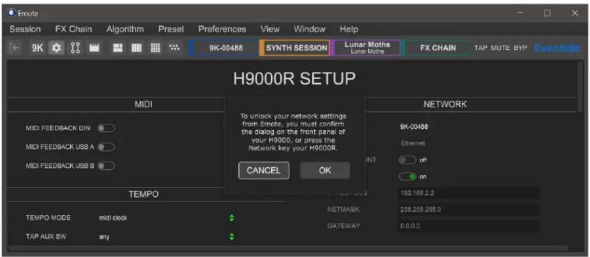
You will then have 30 seconds to confirm the dialog on the front panel of your H9000, or press the Network button on your H9000R. The network selection field in Emote will be unlocked, and it will now no longer be greyed out. This generates a temporary encryption key, which is used to protect usernames and passwords sent via Emote. You will then have 2 minutes to select and connect to your main network, after which you would need to re-do the handshake process to unlock the network selection field again.
When the network connects, quit the Emote software. Re-connect your computer to your main network, and re-open Emote. The H9000 should now be visible in Emote's browser. If it isn't, then reboot your H9000.

Warning
Turn off the access point after you are finished using it. Otherwise it may interfere with Emote's connectivity.
3.2. Overview
Emote's interface contains three key areas:
- Menu bar
- Tool Bar
- Browser
3.2.1. Menu Bar

The Menu Bar offers the following menus:
1. Session
- Open: ctrl/* + o Open a session from a file you have saved to your computer.
- Open Recent: Open a Session that you have recently opened from a file you have saved to your computer.
- Save: ctrl/⌘ + s Save the currently open Session and keep the same name and location.
- Save As: ctrl/⌘ + shift + s Save a Session file to your computer.
- Save To H9000: ctrl/ ^※ + alt + s Save a Session file to the connected H9000.
2. FX Chain
- Open: Open an FX Chain from a file you have saved to your computer.
- Save: Save the currently selected FX Chain and keep the same name and location.
- Save As: Save an FX Chain file to your computer.
- Save To H9000: Save an FX Chain file to the connected H9000.
3. Algorithm
- Import Algorithm: Currently only supports the .9ka file format. To upload algorithms in the .sig2 file format, use Vsig3 instead of Emote.
4. Preset
- Open: Open a Preset from a file you have saved to your computer.
- Save: Save the currently selected Preset and keep the same name and location.
- Save As: Save a Preset file to your computer.
- Save To H9000: Save a Preset file to the connected H9000.
5. Preferences
- Reset Session Load Options
- Reset All Dialogs
6. View
- Toggle Browser ctrl/⌘ + [
- Zoom In ctrl/⌘ + =
- Zoom Out ctrl/⌘ + -
- Reset Zoom ctrl/⌘ + 0
• Show:
- Devices View 5
- Combined View 1
- Setup View 6
- FX Chains View 2
- Direct I/O View 7
- Algorithms View 3
- Scenes View 8
- Parameters View 4
- Select:
- FX Chain 1 ctrl/ ^※ + 1
- Algorithm 4 alt + 4
- FX Chain 2 ctrl/ ^※ + 2 - I/O alt +
- FX Chain 3 ctrl/ ^※ + 3
- Session Tab Q
- FX Chain 4 ctrl/ ^※ + 4
- Chain Tab W
- Algorithm 1 alt + 1
- Algo Tab E
- Algorithm 2 alt + 2
- Preset Tab R
- Algorithm 3 alt + 3
7. Window
- Minimize: ctrl/# + M
- Meter Bridge: Displays all of the H9000's hardware I/O meters in a separate window that allows you to view any physical I/O source or destination in banks of 8. This is useful for debugging setup issues or doing more precise gain staging, as these meters are hardware-based, unlike the software metering provided within each FX chain.
8. Help
- User Guide: ctrl/ ^4 + G
- About Emote: Shows Emote's version.
3.2.2. Tool Bar
The tool bar allows you to select between Emote's Views and offers the following options (from left to right):
1. View Options
- Show/Hide Browser Panel ctrl/# + [ • Show Combined View 1
• Show Devices View 5 • Show FX Chains View 2
• Show Setup View 6 • Show Algorithms View 3
• Show Direct I/O View 7 • Show Parameters View 4
• Show Scenes View 8
2. Color Blocks
• Show Devices View 5 • Show FX Chains View 2
• Show Combined View 1 • Show Parameters View 4
3. Globals
- TAP: Click the TAP button a single time to temporarily display the current tempo used by the H9000. Click the TAP tab repeatedly to manually set a new tempo.
- MUTE: Click the MUTE tab to toggle global mute on/off. This does not affect Direct I/O.
- BYP: Click the BYP tab to toggle global bypass on/off.
- Eventide: Hover your mouse over the Eventide logo to view Emote's version number.

Note
Keyboard shortcuts are only supported in the standalone version of Emote.
The Browser Window may be shown/hidden in Devices View, Combined View, FX Chain View, Algorithm View, and Parameter View.
To load a Session, FX Chain, Algorithm, or Preset, drag it from the Browser Window and drop it onto the appropriate spot in the middle of the main screen. This dragging concept also extends to other areas such as moving algorithms, or creating Input/Output connections. Emote makes use of the “drag and drop” method for most operations. Alternatively, you can double-click any item in the Browser Window to load it, or select it with your mouse or arrow keys and pressRETURN
3.2.3.1. Adding and Removing Sessions
- Use the mouse to drag and drop a session (preset or user-created) from the browser to the middle of the screen. The session will then load.
- If you have a session file on your computer that you'd like to open in Emote, you can go to Emote's Session menu and click Open. From there, you can browse your computer's file system to find your desired session. These files will be prefixed with .9ks
- You can also type text into the search box at the top of the browser to find a particular session. Click the "X" to clear the search box and show all sessions.
- To delete a session permanently, right-click the session in the browser and click delete.
- To clear a session, either load one of the default sessions numbered 1001-1008, or delete everything in the current session. Note that at least 1 FX Chain must always be present within a Session.
3.2.3.2. Adding and Removing FX Chains
- Use the mouse to drag and drop an FX chain (preset or user-created) from the browser to the specific FX chain slot you wish to populate. The FX chain will then load.
- You can also type text into the search box at the top of the browser window to locate a particular FX chain. Click the X next to the search box to clear the search field and show all FX chains.
- To remove an FX chain from a session, drag the FX chain you want to remove back to the browser window on the left and drop it. The FX chain will then be removed, after first prompting you with an "Are You Sure?" message.
- To delete an FX chain permanently, right-click the FX chain in the browser and click delete.
- To clear an FX chain, either load one of the default template FX chains numbered 1601-1615, or delete all algorithms and audio connections in the FX chain. Note that at least 1 algorithm must always been present within an FX Chain.
3.2.3.3. Adding and Removing Algorithms
Type text into the search box at the top of the Browser window to locate a particular algorithm.
Algorithms that match your search will appear in the browser. If the algorithms have presets then the number of presets will be shown in a circle to the right of the algorithm's name. Click the circle to show and hide the algorithm's presets. Click the X next to the search box to clear the search field.
Emote also offers powerful tag filtering capabilities, built to quickly narrow the choices from the large number of available algorithms.
- In the algorithm tab of the browser window, you will see a list of available tag categories to choose from. Categories include Effect Type, Product Type, Instrument Type, and Inputs/Outputs.
- Click on a category to view its contained tags, then click on a tag to toggle it on/off.
- The browser will now display algorithms that match all of the tags that are currently highlighted in red.
- To remove tags, click on your previously selected tags to un-highlight these selections.
- Clicking "Sort By" allows you to sort algorithms by ID ascending, ID descending, name, most used, and last used.
- Right-click an algorithm in the browser and select "more info" to display its description.
3.3. Views
Emote's interface provides various Views that focus on different aspects of the H9000's controls.
3.3.1. Devices View
![9K-00464 9K-00464 Device Type: H9000 Status: Connected Firmware Version: 2.0.2[8] (381b552fe) Auto Connect SYSTEM INFO Model: H9000 (Rev G) Name: 9K-00464 Serial: 9K-00464 Firmware: 2.0.2[8] (381b552fe) UPDATES DSP MODULES DSP A MADI Rev. ID: 54:10ac:87.0c:22 Rev. B ID: 54:10ac:66a:123 DSP 2 Rev. B ID: 54:10ac:67.0a:93 DSP 3 Rev. B ID: 54:10ac:67.0a:93 DSP 4 Rev. B ID: 54:10ac:68a:37 EXPANSION CARDS Firmware: 11 DSP B PT | HDX Rev. 3 ID: 80:1f:12:cf:10:89 Firmware: 10 DSP C Dante™ Rev. 11 ID: 64:10ac:bc:86:15 Firmware: 3](/content/2026/05/903611/images/340bb48f75dada76bf94340b7a8d111e2625a67b417df55b12f29dd4b1812c7e.jpg)
Fig. 3.1 Devices View
In Devices View, the Browser window displays the available H9000s present on the local area network. Click the “Connect” toggle above the H9000 icon to connect to the desired H9000. Emote allows you to connect to multiple H9000 units at once. You can then click in the Browser on the specific unit that you wish to control at any given time. You can also activate the Auto-Connect feature of a given H9000 to have it automatically connect to that unit when Emote is launched on a specific machine.
- Click on the "+" Icon at the bottom of the Browser to manually enter the IP address of an H9000 on the network. This feature can be useful if Emote is not displaying a unit that you know is available on the network.
- Right-click the H9000 device icon to download a system report. This may be useful when requesting customer support.
• Devices View displays information for the currently selected H9000, such as firmware version, number of installed DSP modules, types of expansion cards and their firmware versions, etc.
System info
- Model Number: Displays the H9000's model number and Rev version.
- Name: Displays a custom name that can be assign to the H9000.
- Serial: Displays the H9000's serial number.
- Firmware: Displays the H9000's currently installed firmware version.
- Click "UPDATES" to update your H9000's firmware.
- Click "DUMP DATA" to backup your H9000 before updating.

Note
Please update the H9000's firmware before updating the Emote software. Otherwise, Emote may not be able to connect to the H9000.
DSP modules
Displays the H9000's four DSP Modules. If a DSP module is displayed as (unoccupied) or OFFLINE, please refer to Section A.5: USB Self-Test Mode.
Expansion Cards
Displays any installed expansion cards and information about them, e.g., firmware version.
3.3.2. FX Chains View
FX Chains View allows loading of specific FX chains into available slots and also offers adjustments of FX chain settings.

Fig. 3.2 FX Chains View
3.3.2.1. Adjusting FX Chain Settings
- Use the mouse to adjust the on-screen controls for each FX chain, including:
- Mute
- Bypass
- Input and output levels
-
Mix
-
Alt/Option + click the level faders or mix control to return them to their default state.
- Double-click the FX chain name to type a new title, then press the RETURN key to save the new name.
- Double-click the FX chain container name to type a new title, then press the RETURN key to save the new name.
- Click on an individual algorithm shown in the FX chain to adjust its parameters.
- Click on the input or output block of an FX chain to adjust the parameters for the audio input/output faders, and the functions for that FX chain.
3.3.3. Algorithms View
Algorithms View allows you to:
- Edit input/output routings to/from an FX chain.
- Edit algorithm routings within an FX chain.
- Mute and bypass individual algorithms.

flowchart
graph TD
    A["CrushStation Bottom Feeder"] --> B["HarPeggiator MENACE"]
    B --> C["MangledVerb SCREAMWARP"]
    C --> D["Chorus Warmith"]
    D --> E["USB"]
    style A fill:#f9f,stroke:#333
    style B fill:#ccf,stroke:#333
    style C fill:#cfc,stroke:#333
    style D fill:#fcc,stroke:#333
Fig. 3.3 Algorithms View
3.3.3.1. Editing Algorithm Routing Within an FX Chain
- Click and drag an algorithm to a blank area of the main screen to move or copy that algorithm to one of the other available slots.
- Click and drag an algorithm to another algorithm slot to "swap" the position of the two algorithms.
- Right-click an algorithm to show a menu that gives you the options to delete the algorithm from the FX chain, locate the algorithm within the browser window, or remove all I/O connections from the algorithm.
Note
FX Chain 1 automatically routes newly added algorithms. FX Chain 2, 3, and 4 do not do this.
3.3.3.2. Configuring Audio Connections

flowchart
graph TD
    A["MADI A"] --> B["SELECT"]
    B --> C["MADI A"]
    C --> D["DANTE B"]
    C --> E["AES3 DB25"]
    C --> F["ANALOG"]
    C --> G["USB"]
    H["MUTE"] --> I["1"]
    H --> J["2"]
    K["3"] --> L["17 18 19 20 21 22 23 24 25 26"]
    L --> M["4"]
    N["5"] --> O["8"]
    N --> P["9"]
    Q["6"] --> R["10"]
    Q --> S["11"]
    T["7"] --> U["12"]
    T --> V["13"]
    W["8"] --> X["14"]
    W --> Y["15"]
    Z["9"] --> AA["16"]
    Z --> AB["17"]
    AC["10"] --> AD["18"]
    AE["11"] --> AF["19"]
    AE --> AG["20"]
    AH["12"] --> AI["21"]
    AH --> AJ["22"]
    AK["13"] --> AL["23"]
    AK --> AM["24"]
    AN["14"] --> AO["25"]
    AN --> AP["26"]
    AQ["15"] --> AR["27"]
    AQ --> AS["28"]
    AT["16"] --> AU["29"]
    AT --> AV["30"]
    AW["17"] --> AX["31"]
    AW --> AY["32"]
    AZ["18"] --> BA["33"]
    AZ --> BB["34"]
    BC["19"] --> BD["35"]
    BC --> BE["36"]
    BF["20"] --> BG["37"]
    BF --> BH["38"]
    BI["21"] --> BJ["39"]
    BI --> BK["40"]
    BL["22"] --> BM["41"]
    BL --> BN["42"]
    BO["23"] --> BP["43"]
    BO --> BQ["44"]
    BR["24"] --> BS["45"]
    BR --> BT["46"]
    BU["25"] --> BV["47"]
    BU --> BW["48"]
    BX["26"] --> BY["49"]
Fig. 3.4 FX Chain I/O
- Click on one of the triangles at the top or bottom of the screen to show the audio I/O channels.
- Click on an audio I/O group (USB, AES/EBU, Analog, etc.) to show its available channels.
- Activate a channel either by clicking it, or by holding alt/option and moving the mouse over it. If the channel is locked, shift -clicking will unlock it. The active channel will show up as a routing block bordering its group.
- Click, or click-drag, to make connections between the group routing blocks and the FX chain routing blocks. Once a connection is made, the channel will display a lock icon and be greyed out. Clicking blank space in the FX chain, or hitting the Esc key, ends the connection-making process. Right-click a routing block to remove that block's connections.
Note
Between FX chain routing blocks and Algorithm routing blocks, connections can be multed to multiple destinations, summed from multiple sources, and made in series or parallel.
Between I/O group routing blocks and FX chain routing blocks, any input can be multed to multiple outputs, but multiple inputs cannot be summed to one output.
- I/O channel activations can be transferred from one group to another by right-clicking an I/O group. A menu of eligible I/O groups to transfer to will appear. This feature is not yet supported in Direct I/O View.
3.3.4. Parameters View
Parameters View allows you to adjust specific parameters within an FX chain or algorithm, and assign MIDI, expression, and Function mappings.
- Hold Alt/Option while clicking on a parameter to reset it to its default value.
- Hold Alt/Option, Shift, and/or ctrl/% while scrolling over a parameter to adjust it.
- Hold Shift while adjusting a parameter for fine control.
- Hold ctrl/⌘ while adjusting a parameter for ultra-fine control.
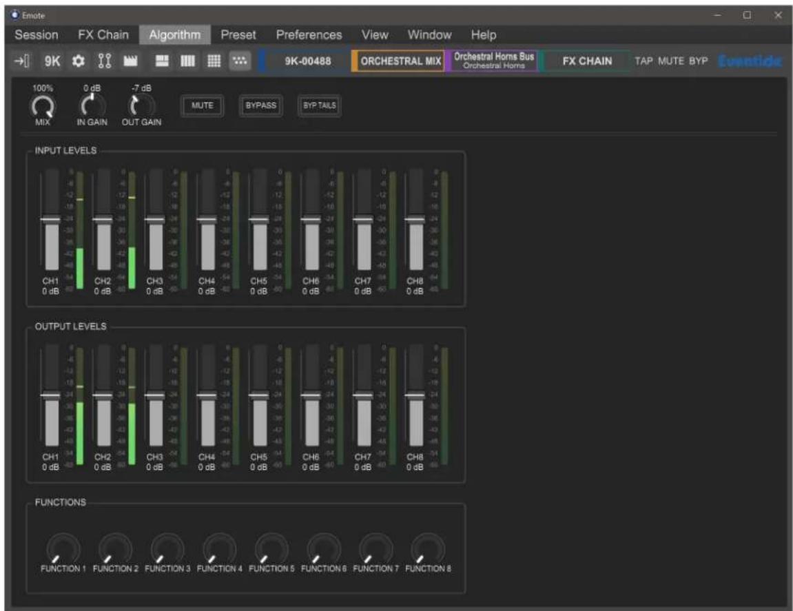
Fig. 3.5 FX Chain Parameters View
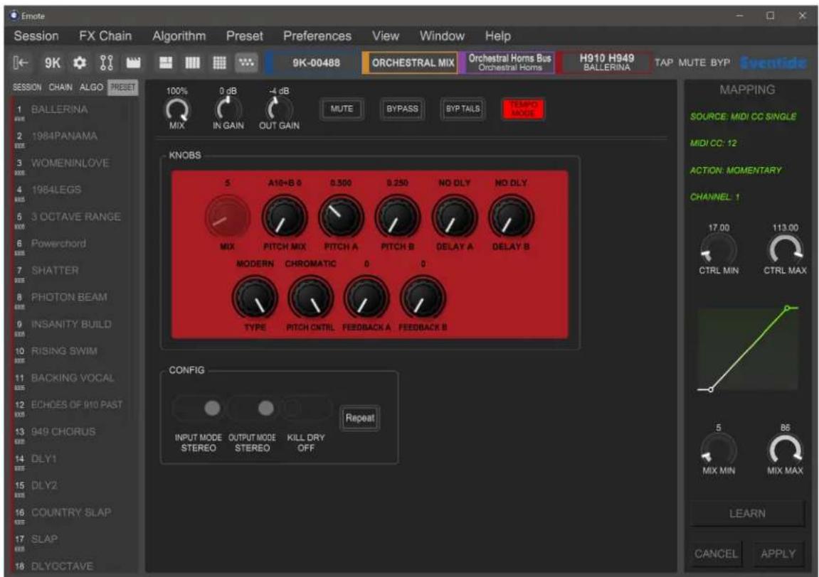
Fig. 3.6 Algorithm Parameters View
3.3.4.1. MIDI and Controller Mapping
Parameters and functions in Emote can be controlled by three different kinds of sources:
• MIDI (see appendix C)
• Expression (see section 2.1.7)
• Functions (see section 3.4.1)
This is done by right-clicking a specific parameter or function, then selecting MAP. Doing so will bring up the mapping window along the right-hand side, where you can select:
- Controller source
- Action type
• Control and parameter minimum/maximum ranges
You can also click the "Learn" button to assign a controller automatically. After pressing Learn, move the physical control you wish to pair with the parameter and click "Apply".
After clicking Apply, the parameter will show a glowing green indicator across the range of the mapping.
3.3.5. Combined View
Combined View shows the FX Chain, Algorithm, and Parameter views all at once. Parameter View is located at the bottom, FX Chains View is located on the left, and Algorithm View is located on the right.
Parameter View displays the parameters of the algorithm or FX chain that is currently selected in Algorithm View, and Algorithm View displays the algorithms within the FX chain that is currently selected in FX chains View.

Fig. 3.7 Combined View
3.3.6. Scenes View
Scenes View allows you to create and edit Scene Maps and their contained lists of scenes. Scenes View has four sections:
- The left side of the screen displays a list of Scene Maps.
- The middle portion of the screen displays trigger sources and scenes contained in the currently active Scene Map.
- The right side of the screen displays options for the currently highlighted scene or trigger source.
- The bottom portion of the screen displays the FX chains in the currently loaded scene.

Fig. 3.8 Scenes View
Scene Maps
The Scene Maps portion of the left side of the screen will be your starting point for creating and using scenes. Each Scene Map can have a total of 128 scenes and only one Scene Map can be active at any given time.
- To create a Scene Map, press the “+” icon at the bottom of the Scene Map portion of the screen and a new map will be added to the list. To rename a Scene Map, right-click its text and a prompt to rename it will appear.
- To delete a Scene Map, highlight the map that you'd like to delete and press the “-” icon. A prompt will ask you to confirm that you'd like to delete this map.
- Double click a Scene Map or press RETURN to activate it. The square to the left of its text will change from grey to red, indicating that it is now active. Double-click it or press RETURN again to deactivate it.
Scenes and Trigger Sources
The middle and right portions of the screen work in tandem to provide all the information needed for creating and customizing your scenes.
The middle portion of the screen offers control of two key areas:
- The list of trigger sources contained within the currently active Scene Map.
- The list of scenes contained within the currently active Scene Map.
Creating and Editing Trigger Sources
- To add a new trigger source, click the "+" icon to the right of the "TRIGGER SOURCES" text.
- Highlight a trigger source, and a list of options will show up on the right side of the screen.
- You will now have the ability to customize your source mode, message type, and MIDI channel (refer to Section 4.8.3.1: Trigger Source Options for more information about specific trigger sources).
- Alternatively, click "Learn" and move your desired external control source to automatically map it as the trigger source.
- To delete a trigger source, click the “-” icon to the right of the trigger source that you’d like to delete.
- To delete all trigger sources, right-click the “TRIGGER SOURCES” text and a prompt will appear to delete all sources.
Creating and Editing Scenes
Scenes can be edited manually or by using the Scene Capture mode.
- To manually add a new action, press the “+” icon to the right of the scene that you’d like the action to be added to. A new action will appear below that scene.
-
Highlight the newly added action and a list of options will appear on the right side of the screen.
-
You will now have the ability to Load, Enable, Mute, or Bypass an FX chain or algorithm for any of the four FX chains.
- To capture a scene, right-click the scene and select the Capture Scene prompt.
- This will take a "Snapshot" of all FX chain settings and parameters in the current session.
- To delete all actions, right-click the scene and select the "Remove All Actions" prompt.
FX Chain Display
The bottom portion of the Scenes page in Emote will display the currently loaded FX chains and algorithms. This is useful for monitoring what changes are being made as you load scenes.
3.3.6.1. Working with Scenes in Emote
Scenes can be selected and activated by clicking on them in the Emote GUI or by sending the appropriate MIDI message as configured above.
- Double-click a Scene Map or press RETURN to activate it. You will now be able to select and activate any of its contained scenes.
- Double-click a scene or press RETURN to activate it. The square on the left side of its text will be turned yellow as it is pending, and then green once it has loaded.
- When sending "Increment Up/Down" MIDI messages, the square to the left of the scene's text will become yellow to indicate it is pending. When a "Load Current" message is sent the square will become green, indicating that it has been loaded.
- If the square to the left of a scene's text is red, then the Scene Map in which it is contained is not active and therefore will not accept MIDI messages.

Note
Scenes cannot be triggered by automating the Emote plugin parameters in a DAW. To trigger scenes from your DAW, send the appropriate MIDI messages via USB-B or a MIDI interface.
3.3.7. Direct I/O View
Direct I/O View functions similarly to steps 2 through 4 in Algorithms View, Configuring Audio Connections (Section 3.3.3.2)
Here, any input can be multed to multiple outputs, but multiple inputs cannot be summed to one output. Also keep in mind the limitations listed in section 4.1.1: Signal Routing.

flowchart
graph TD
    subgraph 9K
        direction TB
        A["1"] --> B["2"]
        B --> C["3"]
        C --> D["4"]
        D --> E["5"]
        E --> F["6"]
        F --> G["7"]
        G --> H["8"]
        H --> I["9"]
        I --> J["10"]
        J --> K["11"]
        K --> L["12"]
        L --> M["13"]
        M --> N["14"]
        N --> O["15"]
        O --> P["16"]
        P --> Q["17"]
        Q --> R["18"]
        R --> S["19"]
        S --> T["20"]
        T --> U["21"]
        U --> V["22"]
        V --> W["23"]
        W --> X["24"]
        X --> Y["25"]
        Y --> Z["26"]
        Z --> AA["27"]
        AA --> AB["28"]
        AB --> AC["29"]
        AC --> AD["30"]
        AD --> AE["31"]
        AE --> AF["32"]
    end

    subgraph 4833 Jams
        direction TB
        B --> B
        C --> C
        D --> D
        E --> E
        F --> F
        G --> G
        H --> H
        I --> I
        J --> J
        K --> K
        L --> L
        M --> M
        N --> N
        O --> O
        P --> P
        Q --> Q
        R --> R
        S --> S
        T --> T
        U --> U
        V --> V
        W --> W
        X --> X
        Y --> Y
        Z --> Z
        AA --> AA
        AB --> AB
        AC --> AC
        AD --> AD
        AE --> AE
    end

    subgraph FX Chain 4
        direction TB
        B --> B
        C --> C
        D --> D
        E --> E
        F --> F
        G --> G
        H --> H
        I --> I
        J --> I
        K --> K
        L --> L
        M --> M
        N --> N
        O --> O
        P --> P
        Q --> Q
        R --> R
        S --> S
        T --> T
        U --> U
        V --> V
        W --> W
        X --> X
        Y --> Y
        Z --> Z
    end

    subgraph Plate
        direction TB
        B --> B
        C --> C
        D --> D
        E --> E
        F --> F
        G --> G
        H --> H
        I --> I
        J --> J
        K --> K
        L --> L
        M --> M
        N --> N
        O --> O
        P --> P
        Q --> Q
    end

    subgraph Pressure
        direction TB
        B --> B
        C --> C
        D --> D
        E --> E
        F --> F
        G --> G
        H --> H
        I --> I
        J --> J
        K --> K
    end

    subgraph DANTE A
            direction TB
            B --> B1["1"]
            B1 --> B2["2"]
            B2 --> B3["3"]
            B3 --> B4["4"]
            B4 --> B5["5"]
            B5 --> B6["6"]
            B6 --> B7["7"]
            B7 --> B8["8"]
            B8 --> B9["1"]
            B9 --> B10["2"]
            B10 --> B11["3"]
            B11 --> B12["4"]
            B12 --> B13["5"]
            B13 --> B14["6"]
            B14 --> B15["7"]
            B15 --> B16["8"]
            B16 --> B17["9"]
            B17 --> B18["10"]
            B18 --> B19["11"]
            B19 --> B20["12"]
            B20 --> B21["13"]
            B21 --> B22["14"]
            B22 --> B23["15"]
            B23 --> B24["16"]
            B24 --> B25["17"]
            B25 --> B26["18"]
            B26 --> B27["19"]
            B27 --> B28["20"]
            B28 --> B29["21"]
            B29 --> B30["22"]
            B30 --> B31["23"]
            B31 --> B32["24"]

    subgraph DANTE A
            direction TB
            A1["1"] & A2["2"] & A3["3"] & A4["4"] & A5["5"] & A6["6"] & A7["7"] & A8["8"] & A9["9"] & A10["10"] & A11["11"] & A12["12"] & A13["13"] & A14["14"] & A15["15"] & A16["16"] & A17["17"]

    end

    subgraph ANALOG
            direction TB
            ANA1["9"] & ANA2["10"] & ANA3["11"] & ANA4["12"] & ANA5["13"] & ANA6["14"] & ANA7["15"] & ANA8["16"]

    end
Fig. 3.9 Direct I/O View
Note
Direct I/O is not effected by the global mute.
3.3.8. Setup View
Please refer to Section 2.1: Setting up Your H9000 for information about these settings.

Fig. 3.10 Setup View
3.4. Using Emote as a Plug-in
Emote can be used in your DAW using VST3, VST, AU, and AAX plug-in formats. Only one instance of Emote is needed in a given DAW project, and it does not matter which audio track it is placed on.
Note
Using Emote as a plug-in does not automatically route audio connections to the H9000, all audio connections must be configured by using your selected DAW's method of routing external audio effects.
The following features are only available while using Emote as a plug-in:
3.4.1. Function Automation
Algorithms in the H9000 can contain any number of parameters; however, most DAW hosts assume that the plug-ins they are hosting will have a static number of parameters. For this reason, it is necessary to use logical parameters to map between what the DAW sees, and what the H9000 has currently loaded. This is achieved by using the H9000's Functions as the interface to the DAW automation. This approach also has the added benefit of being able to aggregate multiple H9000 parameters and automate them in a single automation lane.
When the plug-in version of Emote is loaded into your DAW, the options for automation will appear; each of the four possible FX chains contain eight Functions. Additionally, each FX chain also offers the following options to be automated by the DAW:
- Mute
- Input Gain
- Mix Controls
- Bypass
- Output Gain
To begin automating some parameters:
- Follow the instructions in Section 3.3.4.1 MIDI and Controller Mapping to assign some H9000 parameters to a function.
- In your DAW, write some automation data to the lane corresponding to that specific H9000 function.
Note that while four FX chains are always exposed in the DAW, there may not actually be four chains running on your H9000. In this case, automating any unused ones won't have any effect.
If you replace an FX chain within the H9000, the DAW automation data will still exist, and will apply to whatever parameters are assigned to the Function in the newly created FX chain.

Warning
Because Function data is sent via the network, Functions will stutter if the WiFi is weak, or if the network is congested.
3.4.2. DAW State Recall
When Emote is present as a plug-in in your DAW project, your DAW will automatically save the current state of all of the H9000's settings within Emote. This includes settings for Sessions, FX Chains, Algorithms, Presets, and Scenes.
When you re-open the DAW project and connect to Emote, a pop-up message will display "This DAW project holds state data for 9K-XXXXX. Would you like to restore it?"
- Select YES to restore your H9000's settings for this DAW project. You will be prompted to save your current H9000 session before the H9000's state data from the DAW project is loaded.
- Select NO to keep your current H9000 session. If you later decide you'd like to restore the H9000's DAW state data, reload the DAW project without saving.

Note
While the DAW State Recall is a useful feature for saving your H9000 data, it is best practice to also save an H9000 session with all of your settings.
3.4.3. DAW Tempo Sync
The H9000 can automatically sync its tempo to your DAW project when Emote is used as a plug-in. To do this, set the H9000's Tempo Mode to "DAW" (Section 3.3.8).
In this section, we will show you how to navigate the H9000 front panel and operate the unit.

Note
This chapter is not necessary for the H9000R, which has no front panel controls.
4.1. Getting to know your H9000
4.1.1. Signal Routing
There are a few general “rules” about signal routing in the H9000 which are useful to keep in mind.
- You can only use one digital audio protocol at any given time. This will be determined in your Digital Audio Mode setup.
- When using S/PDIF over the optical ADAT connectors, you can only work at sample rates of 44.1kHz and 48kHz. Sample rates of 88.2kHz and 96kHz are not supported.
- FX chains support 32 inputs and 32 outputs. The outputs of an FX chain can be “multed” to an arbitrary number of physical Input/Output channels, computer audio interface channels, etc.
4.1.2. Soft Keys
The H9000 user interface has context-sensitive "soft keys" on the left and right sides of the display.
There are two different types of soft keys on the H9000:
- "Normal" soft keys: These execute their labeled action when pressed.
- “Latching” soft keys: When pressed, they change the front panel display to a different state. Think of the latching soft keys as a quick way to access “sub-menus” or alternate screens on the H9000. Latching soft keys are visually distinguished by a small triangular “flag” in the top corner of the key.
4.2. Sessions

A Session is the "big picture" for the H9000, a snapshot of the current state of all settings on the unit.
To load a session, press the front panel Sessions button; the button will illuminate to indicate that you are currently working with the Sessions view screen.
The screen will switch to the Sessions view, presenting you with a numbered list of sessions available for loading. The presently loaded session is displayed in the title bar at the top of the screen.
There are several different ways to navigate through the list of sessions:
- Press the cursor up/down buttons or rotate the wheel to scroll through the list one entry at a time.
- Press the cursor left/right buttons to navigate through the sessions list one page at a time.
- The session you have currently navigated will highlight in green.
- Press the Enter button to load the highlighted session.
- The chosen session will load and you will automatically be taken to the FX Chains screen where you can edit the session's FX chains.
4.2.1. Session Screen Soft Keys
The eight Sessions view soft keys offer additional session-related functions:
New
Press the New soft key to create a new session. If you have made changes to the currently loaded session, you will be prompted to save your changes first. You will then see the Create New Session screen. Press the Create New Session soft key (or the Cancel soft key if you change your mind). The new session you have created will be titled "Default Session" and will contain a default FX chain.
Copy
Press the Copy soft key to make a copy of the currently highlighted session. The naming screen will appear, allowing you to create a new name for the copy of the session. This is similar to the "Save As" function on a word processor application, where you can save a copy under a different name.
Delete
Press the Delete soft key to delete the currently highlighted session in the list. You will be prompted with a confirmation screen; press either the Cancel or OK soft keys. Note that you cannot delete factory sessions.
Rename
Press the Rename soft key to rename a currently highlighted session. You will then be presented with the naming screen where you can enter a new name. Note that you cannot rename factory sessions. If you attempt to do so, you will be offered the option of creating a new user session, which you can then rename.
Load
Press the Load soft key to load the currently highlighted session. This soft key duplicates the function of pressing the Enter key when a session is highlighted.
Search
Press the latching Search soft key to bring up the search screen, where you can use the keypad to type a keyword. Sessions containing the letters you type will appear in the filtered list of available sessions.
Preview
Press the latching Preview soft key to get a visual representation of the layout of the session, which includes the number of FX chains, the algorithms in each FX chain, and the physical inputs and outputs. Since loading a session is not an immediate operation, the Preview function offers a quick way to see what the session contains before you actually load it.
4.3. FX Chains

flowchart
graph TD
    A["Add FXCHAIN"] --> B["Plate Reverbs"]
    C["DELETE"] --> B
    D["RENAME"] --> E["Place"]
    F["DIRECT I/O"] --> G["SizPla"]
    H["Press X to return to Sessions."] --> I["Room Reverbs"]
    J["PRESETS"] --> K["MIX"]
    L["MUTE BYPASS"] --> M["GAIN LEVELS"]
Press the front panel FX Chains button to switch the display to the FX Chains view screen, where you can view and edit the FX chains of the currently loaded session.
Press the cursor left/right buttons or use the wheel to highlight the different FX chains. Press the cursor up/down buttons to move through the signal chain blocks in the currently highlighted FX chains block. An FX chain is comprised of audio inputs, the algorithms contained in the FX chain, and audio outputs.
4.3.1. Configuring the Audio I/O of your FX Chain
Use the cursor buttons to highlight the Edit block of the FX chain's audio input section; you will then be presented with choices for selecting both the physical input connector, and the channel number of your selected input connector. Use the wheel to scroll through the available choices. When you have found your desired audio input, press the Enter key. Your chosen input source will now be routed to the input of the FX chain and the display will show a connecting line.
To assign an output to the FX chain, follow the same procedure using the Edit block located at the bottom of the FX Chain display.
Note that you cannot select an output that has been assigned to another FX chain.
4.3.2. Replacing an FX Chain
The middle section of the FX chain block shows the algorithm(s) that make up the current FX chain. To replace the current FX chain with a different FX chain preset:
- Highlight the Replace block and press the Enter key. You will be presented with a list of available FX chain presets.
- Navigate to the FX chain preset you wish to use as a replacement. Press the Enter key to insert the chosen preset into the FX chain.

At any time, you can press the Cancel button to back out of the current screen state and return to the previous state. Pressing the Cancel button a final time will exit the FX Chains screen and return you to the Sessions screen. You can always return to the Sessions screen by pressing the Cancel button once for each iteration of menus you have entered. In other words, if you're in too deep and need to reset, press the Cancel button to get back home.
4.3.3. FX Chain Soft Keys
The FX Chains screen contains eight soft keys that offer the following functions:
Add
Press the Add FX Chain soft key to add a new FX chain to the currently loaded session. You can have up to four FX chains in your H9000. The H9000 will prompt you to select a name and I/O configuration for the FX chain, which will be routed automatically upon creation.
Delete
Press the Delete soft key to delete the highlighted FX chain. Note that you cannot delete the FX chain if it is currently the only one loaded in the session.
Rename
Press the Rename soft key to bring up the naming screen, where you can rename the currently highlighted FX chain container in the session. The name of the FX chain container is distinct from the name of the FX chain preset loaded into it; this can be useful for distinguishing an FX chain's purpose (e.g., Guitar 1, Guitar 2) if the same preset is loaded into multiple containers.
Direct I/O
Press the Direct I/O latching soft key to view the "Direct I/O" screen. Direct I/O lets you use your H9000 as a virtual patchbay; any input can be routed to any output. This lets you take advantage of the H9000's pristine analog converters and complex routing capabilities, even when you do not require any of the signal processing power that the H9000 can provide. Note that this is not an FX chain, but rather a direct audio pathway between a physical audio input and output. Direct I/O assignments are saved within Sessions, and are not effected by the global mute button.
In the Direct I/O screen, use the cursor keys to highlight the input/output you wish to assign, then use the wheel to select the physical input/output you wish to use in your direct I/O pathway.
Additional soft keys are available in the Direct I/O screen:
- Add: Press the Add soft key to create a direct I/O pathway within the Direct I/O screen. Pressing the Add soft key a second time will connect that pathway and add another new pathway.
- Connect: Press the Connect soft key to create a connection between a direct I/O pathway that has not yet been connected.
- Disconnect: Press the Disconnect soft key to delete a direct I/O pathway that you have highlighted. Multiple pathways can be disconnected at once by highlighting the I/O source and pressing the Disconnect soft key.
- Page Left/Right: Press the Page Left/Right soft keys to navigate the different direct I/O pathways you have created when there are more of them than fit on the screen at one time.
Presets
Press the Presets latching soft key to enter the FX chain preset browser. Navigate to the FX chain you wish to load and press the Enter key.

Additional soft keys are available in the Presets browser screen:
- Rename: Press the Rename soft key to rename the currently highlighted FX chain. Note that factory FX chains cannot be renamed.
- Delete: Press the Delete soft key to delete the currently highlighted FX chain preset. Note that factory FX chains cannot be deleted.
- Search: Press the latching Search soft key to bring up the virtual keypad, where you can enter in letters and numbers to search for a FX chain name. As you enter in more characters, the FX chain list is filtered to show only FX chains that contain the characters you are typing.
- Tags: Press the latching Tags soft key to switch the right-hand side of the display to the Tags screen. You will be presented with a list of tag categories. Use the cursor keys and enter key to select.

The following tag categories are included: Effect Type, Product Type, Instrument Type, and Ins/Outs.
Once you have selected a tag category, you will be presented with a menu of tags within that category. Use the cursor and enter keys to select a tag. It will be added to the current tag list and be shown above the tag list. Note that you can select as many tags at once as you like. As you add tags, the main list of FX chains will be filtered to only show presets that correspond to the tag(s) you have selected.
Many of the algorithms on the H9000 will carry multiple tags. For example, Blackhole will fall under the tags of Product Type H9 as well as Effect Type Reverb. This powerful feature is a great way to narrow down the H9000's vast list of FX chains to a more manageable selection that is appropriate to the task at hand.
- Clear: Press the Clear soft key to clear all currently loaded tags and return the main list of FX chains to its untagged state.
Mix
Press the latching Mix soft key to adjust the mix levels of the FX chains present in the currently loaded session. The display will switch to the Mix screen, showing level controls for each FX chain. Use the cursor keys to navigate to the FX chain for which you wish to adjust the level, then use the wheel to adjust its mix level.

Mute/Bypass
Press the Mute/Bypass soft key to mute the currently highlighted FX chain. Press it again to unmute the FX chain. When muted, a red FX MUTE label will appear at the bottom of the FX chain block.
Long-press the Mute/Bypass soft key to bypass the currently highlighted FX chain. Long-press it again to un-bypass the FX chain. When bypassed, a red FX BYPASS label will appear at the bottom of the FX chain block.
Gain/Levels
Short-press the latching Gain/Levels soft key to adjust the output gain levels of the FX chains present in the currently loaded session. Similar to the Mix mode, the display will show level controls for each FX chain. Use the cursor keys to navigate to the FX chain for which you wish to adjust the level, and then use the wheel to adjust the output gain.
Long-press the latching Gain/Levels soft key to show signal levels for the audio inputs/outputs of the currently highlighted FX chain.
Additional soft keys are available in the Gains/Levels screen:
- Control Map: Press the latching Control Map soft key to view external control mapping options for Gains/Levels. Refer to Section 4.5: Parameters for more information about external controller mapping.
- Clear Clip: Press the Clear Clip soft key to clear any overloads that are displayed on the I/O meters.
- Group: Press the latching Group soft key to group together the inputs or outputs of the selected FX chain input or output level. When the latching soft key is illuminated, adjusting the level of either group's fader will adjust the level all faders in each grouping.
4.4. Algorithms
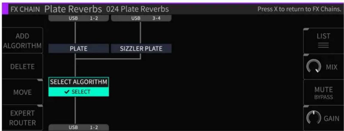
flowchart
graph TD
    A["ADD ALGORITHM"] --> B["PLATE"]
    B --> C["SIZZLER PLATE"]
    C --> D["SELECT ALGORITHM ✓ SELECT"]
    D --> E["USB 1-2"]
    F["MOVE"] --> D
    G["EXPERT ROUTER"] --> H["USB 1-2"]
    I["LIST"] --> J["MIX"]
    K["MUTE BYPASS"] --> L["GAIN"]
In the H9000, each FX chain can contain up to four separate signal processing algorithms. The Algorithms screen is where you work with these algorithms; you can navigate to it by:
- Pressing the Algorithms button on the front panel.
- Highlighting the Edit button in the center portion of an FX chain block, then pressing the Enter button.
The screen will switch to the Algorithms display and the front panel Algorithms button will illuminate.
4.4.1. Algorithms Overview
The Algorithms overview screen displays the algorithms that make up the currently highlighted FX chain. The display shows the different algorithms present, their routing within the FX chain, and the audio inputs/outputs that feed the FX chain.
Rotate the wheel to navigate to the different objects in the FX chain, which include:
- Algorithm processing blocks
- Input and Output blocks
When viewing the Algorithms screen, pressing the Enter button works contextually for whatever object you have highlighted:
- Algorithm: When the Edit label is highlighted, pressing Enter takes you to the Parameters view page (see the Parameters section for more details) When the Replace label is highlighted, pressing Enter takes you to the main list of algorithms to choose from.
- I/O Label: Pressing Enter takes you to the editor screen for the audio inputs/outputs.
4.4.2. Configuring Audio I/O For an Algorithm
To configure the audio I/O on the Algorithms view screen:
- Use the cursor keys to highlight the audio input or output block you wish to configure, and press the Enter key.
- You can then use the cursor keys to highlight the audio I/O category (Analog, Digital, USB, Expansion Card), then cursor over to the channel number and adjust it separately. This type of fine-tuned I/O control is particularly important when an expansion card is present, which can have 32 I/O channels per slot.
- Use the wheel to cycle through the available input or output assignments.
4.4.3. Algorithm Screen Soft Keys
The Algorithms view screen contains eight Soft Keys:
Add Algorithm
- Press the Add Algorithm soft key to add a new algorithm to the currently selected FX chain. A new algorithm block will appear labeled "Select Algorithm".
- Use the cursor keys to highlight the "Select Algorithm" block and press the Enter key.
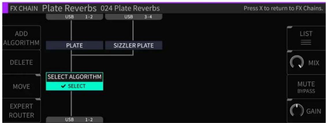
flowchart
graph TD
    A["ADD ALGORITHM"] --> B["PLATE"]
    C["DELETE"] --> B
    D["MOVE"] --> E["SELECT ALGORITHM ✓ SELECT"]
    F["EXPERT ROUTER"] --> E
    B --> G["SIZZLER PLATE"]
    E --> G
    G --> H["USB 1-2"]
    G --> I["USB 3-4"]
    J["LIST"] --> K["MIX"]
    L["MUTE BYPASS"] --> M["GAIN"]
- Use the navigation controls to select an algorithm. Each entry contains helpful info (Ins/Outs, a description of the algorithm, tips on its use, etc.).

Delete
Press the Delete soft key to remove the highlighted algorithm from the FX chain.
Move
Press the latching Move soft key to change the location of an algorithm within the FX chain. You can move the algorithm in an FX chain to be above or below any other algorithm in series, or next to another algorithm in parallel.
Expert Router
The H9000 allows not only serial routing of algorithms, but also parallel and mixed serial/parallel routing too. The expert router page is where you can view and control this aspect of the routing. Press the latching Expert Router soft key. The display switches to a graphical routing matrix, where you can view and edit a high level overview of all of the algorithms present in the current FX chains, their audio I/O assignments, and their signal routing configuration.

flowchart
graph TD
    A["ADD"] --> B["PLATE"]
    C["DELETE"] --> B
    D["MOVE"] --> B
    E["EXPERT ROUTER"] --> F["1 2 3 4 USB"]
    B --> G["SIZZLER PLATE"]
    G --> H["LIST"]
    G --> I["MUTE BYPASS"]
To make adjustments in the Expert Router screen:
- Use the cursor keys to highlight the aspect of the block diagram you wish to adjust (audio I/O block, routing, Algorithm).
- Use the wheel to adjust a highlighted audio I/O routing.
- Use the Move soft key to adjust a routing pathway when it is highlighted.
Mix
Press the latching Mix soft key to change the display to a set of mixing controls, which adjust the relative level of each algorithm within the FX chain. Navigate to the algorithm whose mix you wish to adjust, then rotate the wheel to change it.

flowchart
graph TD
    A["Add ALGORITHM"] --> B["MIX 100%"]
    C["DELETE"] --> B
    D["MOVE"] --> B
    E["EXPERT ROUTER"] --> B
    B --> F["MIX 100%"]
    F --> G["LIST"]
    G --> H["MIX"]
    H --> I["MUTE BYPASS"]
    I --> J["GAIN"]
Mute/Bypass
Press the Mute/Bypass soft key to mute the audio output of the currently highlighted algorithm. A red "M" label will appear at the right of the algorithm block when muted. Press the Mute/Bypass soft key again to unmute the audio output.
Long-press the Mute/Bypass soft key to bypass the currently highlighted algorithm. A red "B" label will appear at the right of the algorithm block when bypassed. Long-press the Mute/Bypass soft key again to un-bypass the audio output.
Gain
Press the latching Gain soft key to change the display to a set of gain controls which adjust the output level of each algorithm within the FX chain. The difference between the Gain control and Mix control is that Gain determines the overall signal presence of an algorithm in a FX chain, whereas Mix controls the overall Wet/Dry mix of an individual algorithm and its signal.
List
Press the latching List soft key to view the main list of all algorithms available on the H9000.

To the right of the list is a description field that shows information for the currently highlighted algorithm, including the name, the product from which it is sourced, the numbers of inputs and outputs available, and a description of the algorithm. Note that the description field will usually contain more text than can fit on the display; in this case, use the cursor keys to highlight the description field, then rotate the wheel to view the remaining text. The List screen the contains following soft keys:
- Show Presets: Some algorithms also contain Presets, which are variations of each algorithm with their parameters configured for different sounds. Press the latching Show Presets soft key to show/hide the presets contained within each algorithm.
- Sort Options: Press the Sort Options soft key to select which way the algorithms are sorted, including ID Ascending, ID Descending, Name, Recently Used, and Most Used. Use the cursor up/down keys to navigate to the sort option you wish to use, and then press the Enter key.
- Jump to Loaded: Press this soft key to jump to the algorithm that is currently loaded in the FX chain.
- Search: Press the latching Search soft key to bring up the virtual keypad and enter letters and numbers to search for an algorithm name. As you enter more characters, the list is filtered to show only algorithms that contain the characters you have typed.
- Tags: Press the latching Tags soft key to switch the right-hand side of the display to the Tags screen. You will be presented with a list of tag categories, which you can select with the cursor keys and enter key. Tag categories are: Effect Type, Product Type, Instrument Type, and Ins/Outs.
Once you have selected a tag category, you will be presented with a menu of tags within that category. Use the cursor keys and Enter key to select a tag; it will then be added to the current tag list and be shown above the tag list. You can select as many tags at once as you like.
As you add tags, the main list of algorithms will be filtered to only show algorithms that contain text matching the tag(s) you have selected. This powerful feature is a great way to narrow down the H9000's vast list of algorithms to a more manageable selection, one that is appropriate for the task at hand.
- Clear: Press the Clear soft key to clear all currently selected tags and return the main list of algorithms to its unfiltered state.
-
More: Press the More soft key repeatedly to switch the soft keys above it to alternate functions. These additional soft keys include:
-
Jump to Last: Press this soft key to jump to the previously loaded algorithm.
- Bank Up/Bank Down: Press these two soft keys to quickly jump to the next/previous bank of algorithms. The H9000 algorithms are organized into different banks, each one representing different categories of effects. Each bank begins with a new 3-digit number (100, 200, etc.)
- Rename: Press the Rename soft key to rename the currently highlighted algorithm. Factory algorithms cannot be renamed.
- Delete: Press the Delete soft key to delete the currently highlighted algorithm. Factory algorithms cannot be deleted.
4.5. Parameters

gauge
| Category | Value | | -------------- | ----- | | MIX | 100 | | DECAY | 2.23 S | | SIZE | 90 | | PRE DELAY | 9 mS | | LOW-DAMP | 57 | | HIGH-DAMP | 70 | | H9 Space | -19 | | DISTANCE | 64 | | DIFFUSION | 29 | | MOD-LEVEL | 24 | | TONE | -19 |Each algorithm contains a set of parameters; you adjust these parameters to adjust the sound of the algorithm you have selected.
For example, a reverb algorithm contains parameters for settings such as room size, decay time, pre-delay, and so on. The Parameters screen allows you to view and adjust these parameters.
To switch to the Parameters screen:
- When the Edit label is highlighted, press the Enter key when an algorithm is highlighted. You will be taken to the Parameters screen for that algorithm.
- Alternatively, press the front panel Parameters button.
The Parameters view page offers a handy list on the left-hand side of the screen, which displays:
- The general parameters for the current FX chain container.
- The algorithms currently loaded in the selected FX chain.
- The parameter categories within each algorithm.
Use the cursor keys to highlight the parameter category for which you wish to view the parameters for. The screen will then display the parameters for only that category. Many algorithms contain a lot of parameters, and a single list could be cumbersome.
4.5.1. Editing Parameters in an Algorithm
To adjust a specific parameter:
- Use the cursor up/down keys to navigate to a parameter category. The right-hand side of the screen will display the parameters within that category.
- Use the cursor keys to highlight the parameter you wish to adjust.
- Use the Enter key and/or wheel to adjust the parameter you have highlighted. Note that you can hold the Enter key while scrolling to make fine-tuned parameter adjustments.

Note
You can also use the two middle-left soft keys to page up/down among the parameter categories, or the two outer-left soft keys to page up/down through the algorithms, while highlighting parameters within the parameter view. This can be a faster way to work than using the cursor keys exclusively; you can jump around the screen quickly and don't need to constantly "cursor left" back to the parameter category list.
The parameters screen contains four additional soft keys:
Learn
Press the latching Learn soft key to quickly map any of the parameters you are viewing.

The learn feature is extremely powerful, as it lets you quickly map a wide variety of external controllers to any algorithm parameter. Different aspects of the effects can be adjusted in real time using MIDI controllers, expression pedals, footswitches, control voltages, etc.
The MIDI functionality on the H9000 is "plug and play". You can connect a MIDI device to the 5-pin MIDI-in DIN port, or connect a MIDI class compliant interface to one of the USB connectors. All MIDI Channel configuration is done when individual controllers are mapped, as opposed to in a central MIDI settings screen.
You can map multiple parameters to a single external control source; you cannot, however, have multiple control sources affect a single parameter.
For more complex mapping of multiple parameters to a single control source, please refer to the Functions section of this user manual.
The Learn feature works as follows:
- Press the Learn soft key; you will see a "Press Enter to Learn" label superimposed over each of the parameters on the screen.
- Use the cursor buttons to navigate to the parameter that you wish to map a controller to.
-
Press the Enter button; the highlighted parameter's label will change to "Move Any Controller".
-
Move the external control that you wish to pair to the highlighted parameter.
- The external controller and the parameter are now paired.
Custom Map
The Custom Map feature is also designed to map controllers to H9000 parameters, but with a much finer level of control. It works as follows:
- Use the cursor buttons to navigate to the parameter you wish to custom map a controller to, then press the Custom Map soft key.
- The "Controller Type" pop-up menu will appear, where you can select from the following mapping options:
• Expression Pedal 1-4
- Switch 1-6
- Note On
- Poly Pressure
- MIDI CC Single
- MIDI CC Double
• MIDI Program Change - Channel Pressure
-
Pitch Wheel
-
MIDI Start
- MIDI Stop
- Function 1-8
-
Off
-
Navigate to the controller type you wish to use then press the Enter key.
- You will then be presented with an additional set of controls that allow you to refine the mapping: Control Minimum, Control Maximum, Value Minimum, and Value Maximum.

- Use the cursor keys to navigate between the Control Range and Parameter range controls.
- Press the MIN/MAX soft key to toggle between adjusting the minimum or maximum value of a parameter, then use the wheel to set its value.
Note that it is possible to change the direction of an external control source by inverting its min/max values. For example, if you set the Max value to 0 and the Min value to 100, when you move your external control source the mapped parameter will move in the opposite direction.
- When you have finished, press the OK soft key and the custom mapping will be completed.
- The display will return to the Parameters display. You will now see a green text label above the parameter, showing you the specific controller you have mapped to that parameter.
- To delete a custom mapping, use the cursor to navigate to the parameter mapping that you would like to delete, and press the Custom Map soft key. In the Controller Type menu, select "Off" and the mapping will be deleted.
Random
Press the Random soft key to assign random values to each and every parameter of the current algorithm. This creative function allows you to try out different algorithms in a free-form "what-if" type scenario, because the different parameter values are all selected with no specific purpose or sound in mind. Give it a whirl with your favorite algorithm and see what happens...
Functions
Functions in the H9000 act much like Macros in Ableton Live; they are groupings of parameters that can be adjusted with a single knob. There are eight Functions available in each FX chain.
Every function has three parameters available:
- Range: Press the latching Range soft key to adjust the range of each parameter mapped to any given Function. Each parameter that belongs to a Function has a defined range; it can be as large as the true Minimum/Maximum range of the parameter, or anywhere in-between. The main Function knobs then cause each parameter change to be scaled according to its defined range.
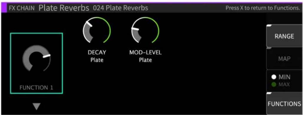
You can use the Min/Max soft key to toggle between adjusting the minimum or maximum value of a parameter's range, as indicated by the white and green end cap markers. These Min/Max values only apply to parameters mapped to a Function knob, not the Function knob itself. To set a min/max value for a Function knob, use the Custom Map feature in the External Control settings.
As detailed earlier in the Custom Map settings, you can change the direction of a parameter's value by inverting the min/max end cap markers. This can be useful for having one Function knob control multiple parameters that move in different directions.
- Map: Press the Map soft key to map specific parameters to the selected Function knob. The Map view displays a condensed view of all the parameters in the FX Chain, allowing their selection for assigning to Functions. The Add/Remove soft key assigns/unassigns the parameter of the selected Function.
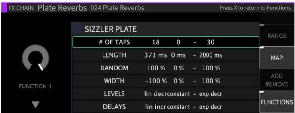
- Highlight the Function knob on the left side of the display.
-
Use the cursor up/down keys to select which of the eight Functions to work with.
-
A list of available parameters will appear; use the cursor up/down keys to highlight the Function you wish to map.
- Press the Add/Remove or Enter key; the highlighted parameter is now mapped to the Function knob you had selected, and that Function's number (e.g., F1) now appears on the left side of that parameter's entry in the list.
-
If a Function is already mapped to a parameter you have highlighted, pressing the Add/Remove soft key will remove the mapping.
-
Learn: Press the Learn soft key to map external controllers to any given Function knob.

flowchart
graph TD
    A["Press Enter to Learn"] --> B["FUNCTION 1"]
    B --> C["FUNCTION 2"]
    C --> D["FUNCTION 3"]
    D --> E["FUNCTION 4"]
    E --> F["FUNCTION 5"]
    F --> G["FUNCTION 6"]
    G --> H["FUNCTION 7"]
    H --> I["FUNCTION 8"]
- Use the cursor keys to highlight one of the eight Functions.
- Press the Enter key to learn a command.
- Move a control on your MIDI controller; that control will now be mapped to the highlighted Function.
The Custom Map dialog can also be accessed through this interface and used the same way as for individual parameters.
External Control
Many algorithms will feature an external control icon that looks like an expression pedal. While any controller can be mapped to any parameter on the H9000, the external controls are specific parameters that are intended to be mapped to a controller by the algorithm's creator. See the Algorithm Library for some examples of this.
To map an external control:
- Use the cursor keys to highlight the Configure button and press the Enter key.
- Follow the prompts to map your controller as described using the Custom Map dialog.
- Your controller will now be mapped to the designated parameter assigned by that algorithm's creator.
4.6. Meters
The H9000 offers an 8-channel set of dedicated three-segment hardware LED meters, positioned above the front panel color display. These LED meters are always active.
The first segment of the hardware LED meter represents signal presence, at any dB level. The second segment, if lit, means the signal is reaching -6 dB, which represents nominal headroom and nominal S/N ratio. The third segment indicates a signal overload, or too much signal presence.
For a more detailed metering view, press the front panel Meters button to switch the color display to the Meters page. The Meters page displays eight channels of metering at a time, and allows you to assign which signal sources are assigned to the display.
4.6.1. Assigning I/O sources to Meters
- On the main metering page, use the cursor buttons or the wheel to navigate to the metering slot to which you wish to assign an audio input or output.
- Press the Enter key, or the latching Assign soft key, to make an assignment.
- You will be presented with a list of every I/O channel; use the cursor up/down buttons or wheel to navigate to the physical input you wish to assign.
- Press the Enter button to accept your choice The selected input/output is now assigned to the highlighted metering channel, and that channel will now show the assignment above the channel number.
More Meters
Press the latching More Meters soft key; the display changes to show metering data for the currently loaded available FX chains. The More Meters screen also has soft keys for the following functions:
• Levels: Press this latching soft key to switch to the Levels screen.
- You are presented with input and output level faders for the currently selected FX chains.
- Use the cursor buttons to navigate to the input or output fader you wish to adjust, then use the wheel to adjust the highlighted fader.
- On the levels screen, press the latching Group soft key to group together level faders. When the latching soft key is illuminated, adjusting the level of either group's fader will adjust the level of all faders in each grouping.
- Clear Clips: Press this soft key to clear any overload clips that have occurred.
- I/O Meters: Press the latching I/O Meters soft key to display the I/O meters screen; you will be presented with metering views for the H9000's banks of physical inputs and outputs, regardless of what custom assignments you have made in the main metering screen.
The I/O meters screen shows which bank of I/O metering you are on in the upper left corner, and which of the 8 pages you are on in the upper-right corner.
On a stock H9000 with no expansion cards installed, the following views are available:
- Digital Audio In 1-8
- USB In 1-8
• Digital Audio Out 1-8
- USB Out 1-8
- Analog In 1-8
- USB In 9-16
- Analog Out 1-8
- USB Out 9-16
Use the cursor up/down buttons or wheel to navigate among the eight pages of metering views.

Note
While in the I/O Meters page, you can use the navigation keys to select a meter. If a physical input or output is routed to or from an FX chain, highlight the meter to see which FX chain it is routed to or from. This is indicated by a purple square under the meter and the corresponding label bar at the bottom of the page.
4.7. Saving and Importing Data
The H9000 allows you to save various types of data, both to its internal memory or a USB drive connected to any of the USB ports.
Once you have saved this data to an attached USB drive, you can import it to a different H9000, allowing you to share your work among machines.

Note
It is recommended to use the included FAT32-formatted USB drive. Please contact support@eventide.com if you need assistance formatting another USB drive.
4.7.1. Saving
Press the front panel Save/Import button. The Save screen will appear and you will be presented with the following options:
- Save Session
- Export Sessions
- Export FX Chains
- Save FX Chain
- Export Presets
- Export Algorithms
- Save Preset

The data to be saved is contextually based on the currently selected item, as follows:
- Save Session will always save the currently loaded session.
- For FX Chains and Presets, the current FX chain and algorithm container selected on the screen will be the items saved for each save option.
At any time, you can refer to the cursor highlight or the title bar in the FX Chains or Algorithms view in order to see the currently selected item.
- Navigate to one of the choices above and press the Enter key to access the naming screen.
- Use the front panel keypad to type a custom name for your saved data, then press the OK soft key. The data will be saved to the H9000's internal storage.
- If a USB drive is attached, you will then be presented with the option to also save the data to the drive as well.
- Press the YES soft key to save your data to the attached USB drive.
• To backup your H9000, refer to Section A.4: USB Dump Data.
4.7.2. Exporting
- If you have a USB drive plugged in, you will also see the "Export" options. The export options will NOT appear in the list if no drive is attached.
- Whereas "Saving" refers to storing something onto the H9000's internal memory, "Exporting" transfers it from the H9000 to the USB drive.
- When saving with a USB drive plugged in, you'll also be given the option to export after the save is complete.
4.7.3. Importing
Once you have saved H9000 data to a USB drive, that data can be imported to any H9000 unit by connecting the drive. Importing works as follows:
- Attach a USB drive containing H9000 data to a USB port of your H9000.
- Long-press the front-panel Save/Import button; the Load Options screen will appear.
- Use the cursor up/down buttons or wheel to navigate to the specific type of data you wish to load, then press the Enter key.
- You will have the option to load Sessions, Presets, FX Chains, and Algorithms.
- Use the cursor up/down keys or wheel to select the data you wish to load, then press the SELECT key; the selected data will be loaded into memory.
- If you wish to load all of the data in the list, press the SELECT ALL soft key instead, or press the CANCEL soft key to cancel out of the load operation.

Note
Any algorithms you load would be sourced from a development environment, such as Eventide's "VSig" software editor. Once you have registered your H9000, the VSig software will be available for download at: https://etide.io/vsig3
4.8. Scenes
Long press the front panel Tap/Scenes button to bring up the SCENES screen.
Scenes are used to control sequenced program changes in the H9000. This mode can be useful when you are using the H9000 in a live environment such as a concert or theatrical production, and wish to "step through" different pre-configured states in an order you have set up in advance.
For example, the main vocalist in a concert may need different reverb parameters at different times during the show; scenes provide a quick, simple way to achieve this:
- You can create multiple "Scene Maps" and select one at any given time
- A Scene Map is a collection of Scenes, along with the Trigger Sources
• Each Scene Map can contain a total of 128 Scenes - A Scene itself can be thought of as a particular state of the FX chains, running under a current session
- The “Scene” denotes a set of actions to be triggered that put the H9000 into that particular state, either an:
- FX chain or algorithm preset to be loaded into a destination container
- A mute/bypass/enable action to be applied to a destination container
4.8.1. Working with Scenes
The right side of the screen displays the 128 available scenes, while the left side of the screen displays a list of Scenes Maps you have created. When entering SCENES mode, the following soft keys are available for Scene Maps:
Create Map
Press this soft key to create a new Scene Map. You will be prompted to name the Scene Map, at which point it will be added to the list of created Scene Maps on the left.

Delete
Press this soft key to delete the highlighted scene.
Activate
Press this soft key to activate the highlighted Scene Map. Once a Scene Map is activated, a green circle will appear to the left of its text, indicating that it will now respond to MIDI messages.
To de-activate a Scene Map, press the Activate soft key while highlighting the currently active Scene Map. The circle to the right of its text will turn red, indicating that it is not active and won't respond MIDI messages. Alternatively, you can activate a different Scene Map.


Note
Only one Scene Map can be active at any given time. When a Scene map is not active it will ignore all MIDI messages.
Rename
Press this soft key to rename the highlighted Scene Map.
4.8.2. Scene Maps
Once a Map is activated, the following soft keys are available for its contained scenes:
Add Action
Highlight a scene on the right-hand side, and press the Add Action soft key. You will be presented with the choices of:
- Scene Capture
- Manual

Scene Capture
This is a way to take a "Snapshot" of the current settings of the Session for a Scene.
Manual
This allows you to create a Scene from a blank template.
Delete
Press this soft key to delete a highlighted scene.
Load
Press this soft key to activate the highlighted scene. The circle to the right of the scene text will turn GREEN, indicating that this scene is now active.
Edit
Press this soft key to edit the highlighted scene. You will have the options to edit with either the Scene Capture or Manual functions.
4.8.3. Trigger Sources
At the top of the Scene Map list on the right-hand side, you'll see the "Trigger Sources" tab. Highlight this tab, then press the Add Source soft key. You will be prompted to select a source mode, message type, and MIDI channel.

- Select Source Mode: You are presented with the source mode options of:
- Load by number
- Increment and load
- Decrement and load
- Increment
- Decrement
- Load current
- Select Message Type: Use the cursor up/down keys or wheel to select an option from the above list, then press the Enter key. You will then be presented with the option to trigger the action using:
- Program change
- CC (MIDI Continuous Controller)
- Note on
- Aux switch
- Select MIDI channel: Use the cursor up/down keys or wheel to select an option from the above list, then press the Enter key. You may then choose from which MIDI channel to receive messages.
4.8.3.1. Trigger Source Options
A “Trigger Source” allows assignment of actions, such as loading a Scene by number, or incrementing/decrementing. You can control Scene changes from the front panel, using Emote, or an external control source such as a MIDI controller or Aux Switch.
Scenes can be triggered in the following ways:
Load By Number
Load By Number works like a traditional program change message; it will load whatever Scene matches the number of the program change message you send, between 0 and 127. Although it usually makes sense to use actual MIDI Program Changes, you can also use Note On or Continuous Controller triggers.
Increment/Decrement
Increment/Decrement switches to the next or previous scene, but keeps it in a pending state. When a scene is in a pending state, the circle to the right of its text will be yellow.
Load Current
Loads a scene from its pending state after being selected with the above mentioned “Increment/Decrement” function. When a scene is loaded from a pending state, the circle to the right of the text will become green, indicating the scene has been loaded.
Increment & Load/Decrement & Load
Switches to the next or previous scene and then loads it immediately. If your scenes are sequenced in the order to be used, it's probably easier to use the Increment & Load/Decrement & Load options. However, if you need to jump around or skip Scenes, you can use Increment/Decrement with the Load Current option.
5. HARDWARE
5.1. H9000 Front Panel

The H9000 front panel contains the following controls:
1. Setup
Press the Setup button to enter the setup menu, where you can configure preferences for your device.
2. Save/Import
Press the Save/Import button to save the different types of presets to internal memory, as well as optionally saving to a FAT32-formatted USB drive. Long-press the Save/Import button to import saved presets into the H9000. See the section "Saving and Importing" for more details.
3. Tap/Scenes
Press the Tap button multiple times to set a BPM tempo (BeatsPerMinute). This tempo setting will be used as a sync reference for time-based effects such as digital delay.
The Tap button's inset LED illuminates in time with the tempo you have set, giving a visual indication of the tempo. Note that if you're not a fan of constant flashing, this can be disabled in the Setup menu.
Long-press the Tap/Scenes button to bring up the SCENES screen. See section 4.8: Scenes for more details.
- Mute/Bypass
Press the Mute/Bypass button in order to mute the audio output of the H9000's FX Chains. Long-press the Mute/Bypass button in order to bypass all processing while still preserving the flow of audio through the I/O connectors and FX chains.
When either Global Mute or Global Bypass is activated, an indication will illuminate in the upper right hand corner of the display until deactivated.
This has no effect on Direct I/O (Section 4.3.3).
- Meters
Press the Meters button to switch the display to a full meter bridge.
- Soft Keys
These eight unlabeled buttons (four on either side of the display) allow you to quickly navigate the H9000's front panel user interface. The soft keys correspond to different functions and are always context sensitive to the currently selected screen.
- Color Display
The H9000's color display allows you to both view and control all aspects of the product while working with its front panel controls. The color display on the front panel is not a touchscreen.
- 8-Channel Meters
These three-segment hardware meters display audio level information for the H9000 and are active at all times.
- Cursor Diamond
Use the four keys of the cursor diamond to navigate up, down, left and right.
- Enter (√)
Press the Enter (check mark) button to confirm or complete an action that you just set up.
11. Cancel (X)
Press the Cancel (X) button to cancel out of an action.
12. Jog Wheel
The large, weighted jog wheel is used to both navigate around the display, as well as to adjust a currently highlighted setting. For example, if adjusting a room size parameter in a reverb algorithm, you can spin the wheel to adjust the specific parameter value.
13. Mode Buttons
The H9000 has four dedicated Mode buttons (SESSIONS, FX CHAINS, ALGORITHMS, and PARAMETERS) that let you switch to any of the editing modes with a single touch. The selected button illuminates to indicate the current mode.
14. Power
Press the latching power button to turn the H9000 on or off.
15. USB-A Ports
The front panel USB ports provide three separate functions:
- Connect a FAT32-formatted USB thumb drive to either of the front/rear panel USB ports to save any H9000 presets you have created or perform an offline firmware update.
- Attach the included USB Wi-Fi adapter to connect the H9000 to a local area network, or to utilize the Wi-Fi access point.
- Connect a class-compliant USB MIDI controller for real-time adjustment of many H9000 functions.
16. Number Pad
Use the buttons on the number pad to enter a custom name when presented with a naming screen. The number buttons operate “vintage mobile phone” style, where each button cycles through multiple letters and also offers special characters.
17. Up/Down Arrows
The up/down arrows act as modifier keys for the number pad when naming an object, allowing you to switch between upper and lower case characters as well as to enter different symbols. You can also use the arrow keys to fine-tune parameter values, as well as scroll through list items.
18. CXL
Press the CXL button to delete a character you have typed when creating a custom name. Long press the CXL button to clear the entire text field.
19. Return
Press the return arrow to confirm the name you entered in the naming field.
5.2. H9000R Front Panel
The H9000R front panel has the following controls:
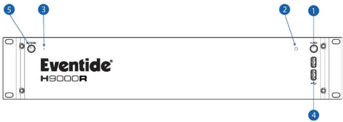
1. Power
Press the latching power button to turn the H9000R on or off.
2. Power LED
This LED illuminates when the H9000R is powered on.
3. Reset Button
Use this pinhole key in the event you need to perform a failsafe boot (as described in Section A: Startup Sequences).
4. USB-A Ports
The front panel USB ports provide three separate functions:
- Connect a FAT32-formatted USB thumb drive to either of the front/rear panel USB ports to save any H9000R presets you have created or perform an offline firmware update.
- Attach the included USB Wi-Fi adapter to connect the H9000R to a local area network, or to utilize the Wi-Fi access point.
- Connect a class-compliant USB MIDI controller for real-time adjustment of many H9000R functions.
5. Network Button
To the left of the pinhole is the Network Button. The LED in the center of this button will flash while the H9000R is starting up. This button is used to unlock the Network Settings (Section 3.1.2.3) in Emote, and to perform various Startup Sequences (Section A).

Note
After pressing the power button on your H9000R, the Network button's LED will flash for about two minutes, then be dim for a few seconds, then brighten. Your H9000R will appear in Emote once the Network LED has brightened.
5.3. Rear Panel
The H9000 and H9000R have identical rear panels. They offer a wide variety of audio and data connections, allowing them to be used in many different environments and workflows.
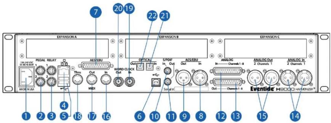
1. Power Connector
Connect the H9000 to your power source using a standard IEC power cable. The H9000's power supply is designed to work from 100VAC to 240VAC, 50-60Hz, without adjustment. Your unit will ship with a power cable designed to work in your territory.
2. Pedal (x2)
The H9000 has 2 14 " TRS inputs that allow for a variety of external control sources including expression pedals, foot switches, control voltages, or a combination.
3. Relay (x2)
The dual 14 " relay connectors allow the H9000 actions to close external circuits. Currently, the relay connectors on the H9000 are not functional. They will become useable in a future revision.
4. Ethernet Connector
This standard RJ-45 connector can connect the H9000 directly to a computer. It can also connect to a local area network via a router, or a switch such as the Dante expansion card (Section 7.2). Once connected, you can view and control the H9000's operations (Section 3.3), and update your H9000's firmware using Emote (Section 6.1).
5. USB A Connector
The rear panel USB A ports provide the same functions as the front panel USB A ports.
6. USB B Connector
Connect the H9000 to your Mac or PC, allowing you to use it as a 16-input, 16-output computer audio interface (Section 2.2).
Note
Due to its design, USB cable has a normal maximum length of about 5 meters (16.4 feet), but you can get longer distances by using an Active USB Extension/Repeater Cable. Exceeding this maximum length without an Active USB Extension/Repeater Cable may cause issues. If you do use a USB extension, be sure it is a USB 2.0 or 3.0 extension, and not a USB 1.0 extension.
7. AES/EBU Connector
This female DB-25 connector allows you to feed the H9000 with eight channels of AES-EBU digital audio, and also allows the unit to output eight channels. TASCAM Standard pinout: https://etide.io/DB-25-Pinout
Note
When connecting the H9000 to another device via the AES-EBU connector, you must use the correct AES-EBU DB-25 cable. If the other piece of equipment uses Yamaha Standard pinout, you must use an AES-EBU TASCAM to Yamaha crossover cable. Please refer to your equipment's documentation to determine what pinout standard it uses.
8. AES/EBU 2-channel Input
This female XLR input accepts a standard 2-channel AES/EBU digital audio signal.
- AES/EBU 2-channel Output
This male XLR connector outputs 2 channels of audio in the AES/EBU digital audio format at the H9000's current sample rate.
- S/PDIF Input
This RCA connector input accepts a standard 2-channel S/PDIF digital audio signal.
- S/PDIF Output
This RCA connector outputs 2 channels of audio in the S/PDIF digital audio format at the H9000's current sample rate.
- Analog Input 8-channel
This female DB-25 connector feeds the H9000 with 8 channels of balanced analog audio input. TASCAM Standard pinout.
- Analog Output 8-channel
This female DB-25 connector outputs 8 channels of balanced analog audio. TASCAM Standard pinout: https://etide.io/DB-25-Pinout
- Analog Input 2-Channel
These dual balanced female XLR connectors accept two channels of balanced analog audio.
- Analog Output 2-Channel
These dual balanced male XLR connectors output two channels of balanced analog audio.
- MIDI Input
The MIDI input allows you to control various H9000 parameters with incoming MIDI messages, using MIDI controller hardware or MIDI software of your choosing. The MIDI input also allows you to synchronize the H9000's time-based effects to an incoming MIDI clock signal. See MIDI Functionality: (Section C)
- MIDI Output
The MIDI Out connector outputs MIDI continuous controller messages, allowing for
18. MIDI THRU
The MIDI THRU connector accepts incoming MIDI signals from the MIDI DIN input and outputs a mirrored duplicate of those signals. This allows you to daisy chain multiple MIDI devices.
19. Word Clock Input
This BNC connector allows the H9000 to sync its digital system clock to an incoming word clock signal. It is compatible with word clock signals at 44.1kHz, 48kHz, 88.2kHz, and 96kHz.
20. Word Clock Output
This BNC connector outputs the H9000's digital clock signal at the unit's currently configured sample rate.
21. Optical Input
The optical input accepts 8 channels of ADAT format digital audio, or 2 channels of S/PDIF format digital audio.
22. Optical Output
The optical output sends 8 channels of ADAT format digital audio, or 2 channels of S/PDIF format digital audio.

Note
The H9000's optical connectors only support sample rates of 44.1kHz and 48kHz; they are not operational when the H9000 is set to run at higher sample rates of 88.2kHz or 96kHz.
23. Expansion A, B, C
These 3 slots allow for optional expansion cards detailed in Section 7: Expansion Cards.
6. FIRMWARE
6.1. Updating Firmware Using Emote

Note
The firmware update process is the same for H9000 and H9000R units.
To update via the internet, your H9000 must be connected to Emote. This can be via a networked connection using ethernet or Wi-Fi, or a direct ethernet connection to your computer. Do not interrupt the network connection to your H9000 or close Emote during the update process.
Once a connection to Emote has been established:
- Go to the Devices View (the button labeled 9K in the menu bar) and locate the H9000 Firmware window at the bottom left corner of the page.
- Click on "Updates" and you will be presented with a list of available firmware updates to choose from.
- Select a firmware version and click the "Install" button; a pop-up message will confirm that you are updating your H9000's firmware. The first progress bar will indicate that the firmware update file is being downloaded and sent to the H9000. The second progress bar will indicate that the firmware is being installed on the H9000. This will also be reflected on the front panel.
- Once the firmware update has been successfully installed, you will be prompted to restart your H9000, which will complete the update process.
- Please restart Emote after the H9000 has rebooted before attempting to connect to an H9000 that has just been updated.
In the event that you need to downgrade your H9000's firmware, please contact support@eventide.com and we will provide you with the correct firmware version to install via the offline USB updater.

Warning
Please be sure not to interrupt power to your unit during the update process; doing so could damage its internal firmware, and result in putting the unit into an unbootable state. In the event this does occur, refer to Section A.2 Recovery Mode to reinstall the firmware on your H9000. It is advised to save your current session before updating the H9000's firmware.
6.2. Updating Firmware Without an Internet Connection
Refer to Section A.2 Recovery Mode for information on updating firmware without an internet connection.
6.3. Updating Legacy Firmware
Please refer to https://etide.io/H9000-Legacy-Update if you are updating your H9000 from firmware version 1.3 or below.
7. EXPANSION CARDS
The H9000 offers additional I/O via three expansion card slots with up to 32 channels of bidirectional audio each. Installation instructions can be found here: https://etide.io/H9000-EXP-Guide
Once installed, your expansion card(s) will be listed on the front panel's Setup page and in Emote's Devices View, and will appear as I/O channels within Emote and on the front panel.
![9K-00464 Default Session FX CHAIN 1 FX CHAIN FX CHAIN TAP MUTE BYP Inventor Device Type: H9000 Status: Connected Firmware Version: 2.0.2[8] (381b552fe) Auto Connect SYSTEM INFO Model: H9000 (Rev G) Name: 9K-00464 Serial: 9K-00464 Firmware: 2.0.2[8] (381b552fe) UPDATES DSP MODULES Rev. B ID: 54:10:ec:87:0e:2 DSP 1 DSP 2 Rev. B ID: 54:10:ec:86:e1.23 DSP 3 Rev. B ID: 54:10:ec:87:0e:93 DSP 4 Rev. B ID: 54:10:ec:86:e3.5f EXPansion CARDS EXP A MADI Rev. 10 ID: d8:80:39:d4:01:34 Firmware: 11 EXP B PT | HDX Rev. 3 ID: 80:15:12:cf:10:99 Firmware: 10 EXP C @Dante™ Rev. 11 ID: 54:10:ec:bc:86:16 Firmware: 3](/content/2026/05/903611/images/74d402e7e9f9e448fb21775ca14465dd987e4f2ac37844c701853dbe232f704f.jpg)

Note
There is no Eventide registration process for H9000 expansion cards.
7.1. MADI

natural_image
Exhibit card and circuit board components (no readable text or symbols)• Supports full AES5 compatibility.
- Sample Rate Clock Sources: H9000 or the selected source.
• 32 In / 32 Out operation from 44.1kHz to 96kHz.
• Optical, Coax, or ExpressCard (RME proprietary) connections.

Note
MADI coax requires 75 ohm cables, but is point-to-point only and does not allow daisy-chaining. Thus, it does not require any external termination. Termination is done internally on both transmitter and receiver ends. T-connectors should never be used.
7.1.1. MADI Setup
These options are available in the Setup page for the MADI Expansion Card:
Source Select
Selects which source the MADI card receives audio from: Optical, Coax, or ExpressCard. The MADI card sends audio to Optical, Coax, and ExpressCard simultaneously.
Tx Format
Auto/56, Auto/64, 56 ch, 64 ch.
Lock Status
Indicates whether your selected port is connected or not. If GREEN, your MADI Expansion card is connected to your MADI interface. If RED, your MADI Expansion card is not connected or being detected by your MADI interface. Check your connections.
7.2. Dante
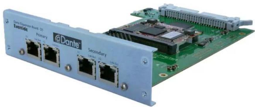
natural_image
Electronic device with network ports and a green circuit board (no readable text or symbols)• Audinate Brooklyn II Dante Module based design
• 32 In / 32 Out operation from 44.1kHz to 96kHz
• Sample Rate Clock Sources: Brooklyn II Module, Dante network, H9000
- AES67 Support
- Either 2 Primary and 2 Redundant Networks Connections or 4 Primary Network Connections
- Integrates with Dante-enabled devices: https://etide.io/dante-enabled
7.2.1. Dante Setup
7.2.1.1. Clock Sync
From a clocking point of view, it is best to think of the Eventide H9000 and its Dante expansion card as two separate devices.
H9000
Once a Dante card is installed, "Exp A/B/C (Dante)" will appear as a clock source option in Emote (Section 3.3.8), and on the front panel (Section 2.1.4). This option syncs the H9000's clock to the Dante card's clock.
Dante
The Dante card's clock is set in Audinate's Dante Controller, which is available here: https://etide.io/latest-dante Dante Controller's Clock Status tab displays the current clock source of the Dante card. This clock source can be set with the "Enable Sync To External" checkbox.
To sync the H9000 to Dante, set the H9000's clock source to "Exp A/B/C (Dante)", and uncheck "Enable Sync To External" for the Dante card in Dante Controller.
To sync Dante to the H9000, set the H9000's clock source to "Int {sample rate}", and check "Enable Sync To External" for the Dante card in Dante Controller.
7.2.1.2. Sample Rate Match
The Dante card's sample rate must be set manually under the Device Config tab in Dante Controller's Device View.
If the H9000's clock syncs to Dante, then the H9000's clock will automatically follow Dante's sample rate.
If Dante's clock syncs to the H9000, then the sample rate in Dante Controller's Device View must be manually configured after changing the H9000's sample rate.
7.2.2. Documentation
https://etide.io/dante-tech-docs

Note
The Dante expansion card is not a network router, but it is a network switch. If Emote is on the same local area network as Dante, and the Dante expansion card is configured in Switched mode, then an ethernet cable can be plugged in directly between the H9000's ethernet port and any of the Dante card's primary ports.
7.2.3. Firmware updates
The H9000 Dante expansion card firmware update is available here: https://etide.io/dante-exp-firmware
To update your H9000 Dante expansion card firmware, first download Audinate's Dante Controller, available here: https://etide.io/latest-dante
The Updater is available in Dante Controller's "view" menu. Import "h9k-dante-io-board-19.1.31.1.dnt" into the Updater by following Audinate's guide here: https://etide.io/dante-firmware-import
7.3. Pro Tools | HD

- 2 DigiLink Mini ports
- DigiLink Connections feature a Primary and a Secondary Port which is switchable between 32-and 16-channel I/O
- LoopSync In and Out connectors
- LoopSync Connections allow you to use Pro Tools to assign the clock source as either the H9000 or another HD device
• 32 In / 32 Out operation from 44.1kHz to 96kHz - Includes 12' DigiLink Mini cable
7.3.1. Pro Tools | HD Setup
These options are available in the Setup page for the Pro Tools | HD Expansion Card:
Sample Rate
Displays the sample rate being output by Pro Tools. This will change depending on the Sample Rate of the Pro Tools Session.
Clock Source
Displays either "Internal" or "LoopSync". If the H9000 is the Clock Source in Pro Tools, then this will display "Internal". If another HD device is the Clock Source in Pro Tools, then this will display "LoopSync" if a LoopSync connection has been established. These settings will also be reflected on H9000's Clock menu page.

Note
Sample Rate and Clock Source are both read only parameters on the H9000's front panel and in Emote. These parameters can only be changed using the Pro Tools Hardware Setup page, or in your computer's audio configuration page, such as the Audio MIDI setup page on macOS.
Interface Mode
Toggles between 32 Channel mode and 16 Channel Mode. In 32 Channel Mode, the expansion card will output 32 channels through the Primary DigiLink port. Use this setting if you are connecting directly to the HD Card to take advantage of all 32 channels. In 16 Channel Mode, the expansion card will output 16 channels through both the primary and secondary port. Use this setting if you are daisy chaining into another HD interface's secondary port since the maximum channel count per DigiLink port is 32.
Connection Status
Indicates DigiLink port connection status. If GREEN, your HD Expansion card is connected to your HD System. If RED, your HD Expansion card is not connected or being detected by your HD System. Check your connections.
Loop Master Status
Indicates what source is being used as the "Loopmaster" in the LoopSync. If GREEN, your H9000 is serving as the "Loop Master" to the rest of your HD System. If RED, your H9000 is clocking to another source through the LoopSync of your HD System.
Clock Control
Allows Pro Tools permission to control your H9000's internal clock via the HD expansion card. When using Pro Tools, toggle this on so that your H9000 can sync seamlessly with your HD System's clocking. When not using Pro Tools, turn this off so that the H9000 will ignore any clock changes you make from Pro Tools.

Note
When Clock Control is enabled, you will not be able to change the H9000's clock settings regardless of whether the HD expansion card is being used or not. Turn Clock Control off to change the H9000's clock settings.
7.3.2. Integration
To use Pro Tools | HD I/O with the H9000, you must connect the expansion card to your HD system via the DigiLink ports. Once this is connected, You must select the HD device as your Playback Engine in Pro Tools. In the example below, we are using an HD Native Thunderbolt to integrate it into the HD environment.
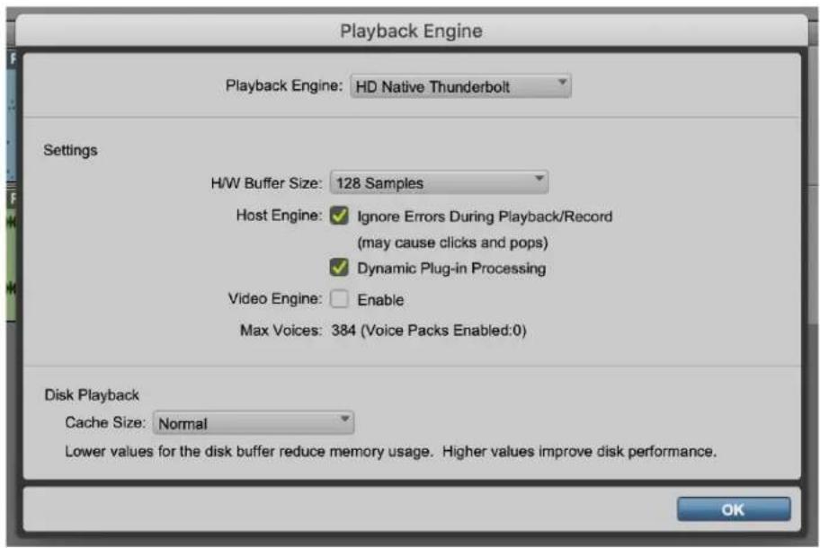
Once you have the HD device selected as your playback engine, you can now route audio to and from the H9000 via the expansion card's DigiLink ports.
To use the H9000 as a H/W insert in Pro Tools, first you have to check your Hardware Setup page in Pro Tools to see which inserts the H9000 will correspond to.

On the left side of the Hardware Setup page, your HD devices will appear in the Peripherals window. In this case, we have our HD audio interface plugged into the Primary port, and the H9000 plugged in to the Secondary port of the HD Native. In the Peripherals window, the HD audio interface will show up as HD I/O #1 and #2, and the H9000 will show up as HD I/O #3 and #4.
Highlighting a device in the Peripherals window will allow you to view its I/O settings. In Pro Tools, the hardware inserts for HD I/O #1 and #2 will appear as A 1-16 and B 1-16. Since the H9000 is plugged into the Secondary port (HD I/O #3 and #4), its corresponding hardware inserts will be C 1-16 and D 1-16. Note that the I/O of the HD expansion card will show up in the Pro Tools Hardware Setup page as “Analog 1-16” when these are, in fact, digitally routed to the H9000.

Note
In Pro Tools, 1st party HD interfaces will show up with their proper name (i.e. HD Native). The H9000 and other 3rd party HD devices will show up as “HD I/O” with its corresponding device number as shown above.
If a LoopSync connection has been established between your H9000 and another HD device, you will be able to use either the H9000 or the other HD device as the clock source. To select a clock source, click on the Clock Source tab and a drop down menu will appear. In the above example, selecting HD I/O #1 or #2 “Internal” will set the HD audio interface as the clock source and the H9000 will be synced to it. Alternatively, selecting HD I/O #3 or #4 “Internal” will set the H9000 as the clock source.
In the example below, the Pro Tools insert C 5-6 will route to the H9000 HD expansion I/O 5-6.

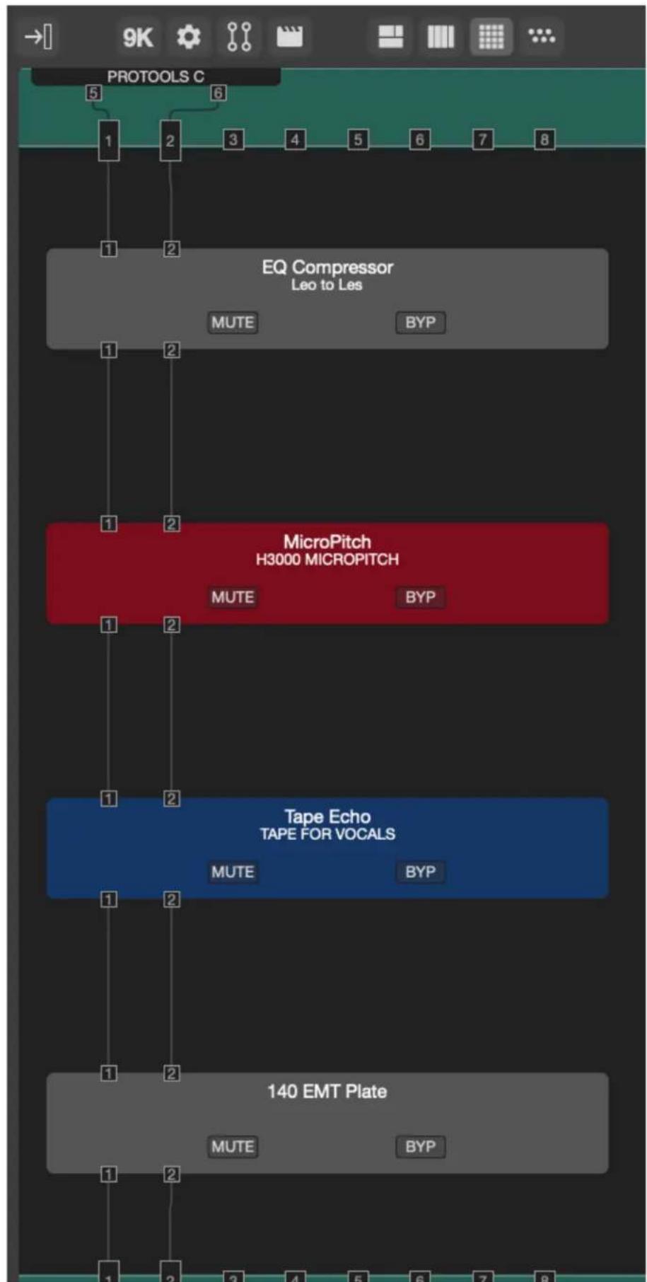
flowchart
graph TD
    A["PROTOOLS C"] --> B["EQ Compressor<br>Leo to Les"]
    B --> C["MUTE BYP"]
    C --> D["MicroPitch<br>H3000 MICROPITCH"]
    D --> E["MUTE BYP"]
    E --> F["Tape Echo<br>TAPE FOR VOCALS"]
    F --> G["MUTE BYP"]
    G --> H["140 EMT Plate"]
    H --> I["MUTE BYP"]
Note that the H9000 displays the expansion card I/O as a single 32-channel device, while Pro Tools divides the I/O into two separate 16-channel devices. In the above example, expansion card I/O 1-16 will appear in Pro Tools as C 1-16, while expansion card I/O 17-32 will appear in Pro Tools as D 1-16. For example, if you want to route your audio into HD expansion inputs 19-20, they will appear in Pro Tools as D 3-4.
7.3.3. Using Multiple Pro Tools | HD Expansion cards
In order to use more than one Pro Tools | HD expansion cards, the clocking must first be setup correctly:
- If there are no other HD devices in the system, LoopSync is not needed.
- Only one card can have Clock Control enabled AND it must be the card that Pro Tools selects as the "Loop Master" (Internal/AES/Word Clock).
Let's assume that HD expansion card A is connected to the HD system's Primary port and HD expansion card B is connected to the Secondary port:
- In the Pro Tools Hardware Setup page, if HD1 or HD2 is selected as the "Loop Master," then HD expansion card A needs to have Clock Control ON.
- If HD3 or HD4 is selected as the "Loop Master," then expansion card B needs to have Clock Control ON.
- If another HD device is the "Loop Master," either expansion card can have Clock Control enabled.
8. LEGALESE
8.1. Safety and Warranty
Safety Information
- Do not remove any covers or panels from the unit when the power is connected.
- No operator access to the internals of the unit is permitted; servicing must be performed by qualified personnel only.
- The unit must not be operated with a damaged or ungrounded power cord.
- Suitable ventilation must be provided for the unit at all times. In particular, the side vents must not be obstructed. It is best if there is an inch or more clearance between the top of the H9000 and the bottom of the units above and below.
Limited Warranty
The Eventide H9000/H9000R unit covered by this warranty is built to exacting quality standards and should give years of trouble-free service. If you are experiencing problems which are not cleared up in this manual, your recourse is this warranty.
What the Warranty Does and Does Not Cover
Eventide Inc. warrants the above-identified unit to be free from defects in workmanship and material under normal operation and service for a period of one year from the date of purchase, as detailed below.
At our discretion within the warranty period, we may elect to repair or replace the defective unit. This means that if the unit fails under normal operation because of such defect, we will repair the defective unit at no charge for parts or labor. We also assume a limited responsibility for shipping charges, as detailed below.
The warranty does not extend beyond repair or replacement as stated herein and in no event will we be responsible for consequential or incidental damages caused by any defect, and such damages are specifically excluded from this warranty. Our sole obligation is to repair or replace the defective unit as described herein.
The warranty DOES NOT COVER any damage to the unit regardless of the cause of that damage. The unit is a complex piece of equipment that does not react well to being dropped, bounced, crushed, soaked or exposed to excessively high temperatures, voltages, electrostatic or electromagnetic fields. If the unit is damaged for these or similar causes, and the unit is deemed to be economically repairable, we will repair it and charge our normal rates.
The warranty DOES NOT COVER shipping damage, either to or from Eventide. If you receive a new unit from us in damaged condition, notify the carrier and us; we will arrange to file an insurance claim and either repair or exchange the unit.
If you receive a new unit from a dealer in damaged condition, notify the dealer and the carrier.
If we receive the unit from you with apparent shipping damage, we will notify you and the carrier. In this case, you must arrange to collect on any insurance held by you or your carrier. We will await your instructions as to how to proceed with the unit, but we will charge you for all repairs on damaged units.
Who is Covered Under the Warranty
The warranty applies to the original purchaser of a new unit from Eventide or an Authorized Eventide Dealer. Demo units are also covered by this warranty under slightly different circumstances (see below).
Units that are used, or have been used as part of a rental program, are not covered under any circumstances.
It is your responsibility to prove or to be able to prove that you have purchased the unit under circumstances which activate the warranty. A copy of your purchase invoice is normally necessary and sufficient for this.
If you have any questions about who is an Authorized Eventide Dealer, call us. Units with the serial number plate defaced or removed will not be serviced or covered by this warranty.
When the Warranty Becomes Effective
The one-year warranty period begins on the day the unit is purchased from an Authorized Eventide Dealer or, if the unit is drop-shipped from Eventide, on the day shipped, plus a reasonable allowance for shipping delays. This applies whether or not you return your warranty registration form.
Warranty Information
When we receive a unit, this is how we determine whether it is under warranty:
-
If the unit was shipped from our factory within the past calendar year, we assume that it is under warranty unless there is evidence to the contrary, such as its having been sold as used or rented, etc.
-
If the unit was shipped from our factory more than a calendar year ago, we assume it is not under warranty unless:
-
There is a warranty registration form on file showing that it has been purchased within the past year under appropriate conditions.
-
You send a copy of your purchase invoice indicating warranty status along with the unit.
-
If the unit was used as a demo, the warranty runs from the date that it was received by the dealer. The original purchaser gets the unexpired portion of that warranty.
When you send a unit for repair, you should indicate whether or not you believe it to be under warranty. If you do not say the unit is under warranty, we will charge you for the repair and we will not refund unless the charge was caused by an error on our part. If you believe the unit to be under warranty and you do say it is but we disagree, you will not incur any charges until the dispute is resolved.
Reading the above, you can see that it is to your advantage to send in the warranty registration form when you purchase the unit. If we know who you are, we can send you updates and notifications, and advise you of our new products. It will also enable you to receive pre-shipment of certain parts.
Who Performs Warranty Work
The only company authorized to perform work under this warranty is Eventide Inc., Little Ferry, New Jersey. While you are free to give personal authorization to anyone else (or to work on it yourself), we will not honor claims for payment for parts or labor from you or from third parties.
However, we and our dealers do try to be helpful in various ways. Our dealers will assist, usually without charge during the warranty period, in:
- Determining whether there is a problem requiring return to the factory.
- Alleviating user error or interconnection problems that may be preventing the unit from operating to its full capability.
We are available for email and telephone consultation if the dealer is unable to assist.
If a part is found to be defective during the warranty period and you wish to replace it yourself, we will normally ship the part immediately at no charge, provided your warranty registration form is on file. We reserve the right to request that the defective part be returned to us.
Shipping Within the 50 United States
You are responsible for getting the unit to our door at no cost to us. We cannot accept collect or COD shipments.
We will return the unit to you prepaid, at our expense, using an expeditious shipping method, normally United Parcel Service. In areas not served by UPS we will ship by US Mail.
If you are in a hurry and want us to use a premium shipping method (such as air express, next day air, etc.), be sure you tell us and agree to pay shipping charges collect. If you specify a method that does not permit collect or COD charges, remit sufficient funds to prepay shipping.
Shipping Outside the 50 United States
If you purchased the unit from a dealer in your country, consult with the dealer before returning the unit.
If you wish to return the unit to us, please note the following:
- The unit must be prepaid to our door. This means that you are responsible for all shipping charges, including customs brokerage and duties. When a unit is shipped to us it must be cleared through United States Customs by an authorized broker. You must make arrangements for this to be done. Normally, your freight forwarder has a branch in the United States, which can handle this transaction. If you want our assistance, you must notify us before shipping the unit for repair, giving full details of the shipment, and including a minimum of \$250.00 in US funds to cover the administrative and brokerage expenses. Any balance will be applied to the repair charges or refunded. If a balance is due to us, we will request a further prepayment.
- All shipments will be returned to you collect. If this is impossible because of shipping regulations or money is due us, we will request prepayment from you for the appropriate amount.
- All funds must be in US dollars. Payment may be made by check drawn on any bank in the US, or by telegraphic funds transfer to our bank. If you send US currency, be sure that it is sent by a method you can trace, such as registered mail. If you wish to pay by Letter of Credit, be sure that it affords sufficient time for work to be performed and the L/C negotiated, and that it is free from restrictive conditions and documentation requirements.
- We reserve the right to substitute freight carriers. Although we will attempt to honor your request for a specific carrier, it is frequently necessary to select a substitute because of difficulties in communication or scheduling.
This warranty gives you specific legal rights and you may also have other rights, which vary from location to location.
8.2. Federal Communications Commission Statement
FC This device complies with Part 15 of the FCC Rules. Operation is subject to the following two conditions:
- This device may not cause harmful interference.
- This device must accept any interference received, including interference that may cause undesired operation.
This equipment has been tested and found to comply with the limits for a Class A digital device, pursuant to part 15 of the FCC Rules. These limits are designed to provide reasonable protection against harmful interference in a residential installation. This equipment generates—and can radiate—radio frequency energy and, if not installed and used in accordance with the instructions, may cause harmful interference to radio communications. However, there is no guarantee that interference will not occur in a installation.
If the equipment does not cause harmful interference to radio or television reception, which can be determined by turning the equipment off and on, the user is encouraged to try to correct the interference by one or more of the following measures:
- Reorient or relocate the receiving antenna.
- Increase the separation between the equipment and the receiver.
- Connect the equipment into an outlet on a circuit different from that to which the receiver is connected.
- Consult the dealer or an experienced radio/TV technician for help.

Warning
This is a Class A product. In a domestic environment this product may cause radio interference in which case the user may be required to take adequate measures to correct this interference.
Class A ITE
Class A ITE is a category of all other ITE which satisfies the class A ITE limits but not the class B ITE limits. Such equipment should not be restricted in its sale but the above warning shall be included in the instructions for use.
CE Class A (EMC)
CE This product is herewith confirmed to comply with the requirements set out in the Council Directives on the Approximation of the laws of the Member States relating to Electromagnetic Compatibility Directive 2004/108/EEC.
A. STARTUP SEQUENCES
The H9000 contains various "Startup Sequences". By pressing and holding different button combinations while powering up, you can perform the following functions:
A.1. Soft Reset
H9000 - Hold down the SESSIONS and FX CHAINS buttons while turning on the H9000 by pushing the power button. This will clear the current state of the H9000, but will not enable the Wi-Fi Access Point. This does not affect any of your saved sessions or presets, but will clear the currently loaded session and all settings in Setup View, including your network and authentication settings.
H9000R - Hold down the NETWORK button while turning on the H9000R by pushing the power button. This will clear the current state of the H9000, and also enable the Wi-Fi Access Point (as long as a Wi-Fi adapter is plugged into a USB-A port on the H9000). This does not affect any of your saved sessions or presets, but will clear the currently loaded session and all settings in Setup View, including your network and authentication settings.
- The Wi-Fi access point will appear in your computer's network settings as "H9000" followed by a string of automatically generated characters, or the custom name you have assigned to your unit.
- You will be required to enter an automatically generated password to connect to the Wi-Fi Access Point. This will be your H9000's serial number in the format "9K-XXXXX".

Warning
Turn off the access point after you are finished using it. Otherwise it may interfere with Emote's connectivity.
A.2. Recovery Mode
Recovery Mode can be used to install an update from a FAT32-formatted USB flash drive. This mode is useful if a problem occurs when updating the H9000's firmware.
Note
A FAT32-formatted USB drive with a valid firmware installer must be connected to your H9000 before it is powered on to connect to Emote in recovery mode.
To install an update using a FAT32-formatted USB flash drive:
- Download the "USB Installer for H9000", which is available on the Eventide website. If for any reason you need a specific firmware version, please contact support@eventide.com and we will provide you with the correct USB installer.
- Unzip the zip file.
- Inside the folder should be 2 files, "usb-updater.sqz" and "usb-updater-info.xml".
- Copy these 2 files to the top level of a FAT32-formatted USB flash drive.
- Eject the drive from your computer and connect it to a USB port on the H9000.
- On the H9000:
- Hold down the CHECK and X buttons while turning on the H9000 by pushing the power button.
- Wait for the H9000 to boot into recovery mode.
- Follow the on-screen instructions.
- On the H9000R:
- Power on the H9000R while inserting a paperclip into the pinhole that is located to the right of the front panel NETWORK button. The NETWORK LED will start blinking.
- If your H9000R is connected directly to your computer or router via ethernet, you will be able to connect to the H9000R RECOVERY device in Emote without any further configuration.
- If a Wi-Fi adapter is plugged into a USB-A port on the H9000R, it will become visible on your computer's list of available Wi-Fi networks as a RECOVERY Access Point once the NETWORK LED stops blinking. Once it becomes visible, connect your computer to it.
- You will be required to enter an automatically generated password to connect to the recovery device. This will be your H9000's serial number in the format "9K-XXXXX".
-
When the NETWORK LED stops blinking, your H9000R should be visible in Emote, displayed as the unit's serial number, followed by the word "recovery". You can connect to the hardware as usual, however the options presented in Emote, once connected, will be different than usual. You can access:
-
The USB updater (if a valid USB device with updater files was connected at boot)
- Functions for:
- Clear Current State
- USB Data Dump
- Reinitialize (Factory Reset)
Click the "USB Update" button to install the firmware from the USB flash drive.
- To exit Recovery Mode, simply power cycle the device and it will boot into its normal state. If you've performed a firmware update, an option will appear to do this automatically from Emote.
A.3. Factory Reset

Warning
This operation will remove all of your stored Sessions, Algorithms, and Presets.
H9000 - Hold down the SESSIONS, FX CHAINS, and ALGORITHMS buttons while pushing the power button.
H9000R - Push a paperclip into the pinhole while pushing the power button. Connect to the recovery device in Emote and select the "Reinitialize" option.
A.4. USB Dump Data
Insert a FAT32-formatted USB drive into any USB port to backup the contents of your H9000.
H9000 - Hold down the SESSIONS button while pushing the power button. Once booted, a message will display on the front panel saying "User data dumped to USB memory."
H9000R - Push a paperclip into the pinhole while pushing the power button. Connect to the recovery device in Emote and select the "Dump Data" option. A USB installer of the most recent firmware version must be present on the USB stick for this to work in recovery mode.
The USB Dump Data feature can also be accomplished using Emote for either type of H9000. In the Devices View, click the Update button, and a button to "Dump Data" will be available. This is useful if you'd like to make a backup of your H9000's data before updating its firmware.
A.5. USB Self-Test Mode
The USB self-test is a way to test various functions and diagnose potential issues on the H9000.
- Download and unzip the USB self-test zip file available on the H9000 Installers webpage: https://www.eventideaudio.com/support/product/9106/installers
- Inside the folder should be 2 files. "usb-self-test.sgz" and "usb-self-test-info.xml".
- Copy these 2 files to the top level of a FAT32-formatted USB flash drive. Make sure there are no H9000 USB updater files on the drive.
- Eiect the drive from your computer and connect it to a USB port on the H9000.
- On the H9000, power on the unit while holding both the CHECK and X keys for at least two seconds and wait for it to boot into self-test mode. You will see a progress bar that indicates the tests are being performed.
- On the H9000R, power on the unit while pushing a paperclip into the pinhole and wait for it to boot into self-test mode. The NETWORK LED will blink until the tests are complete. The LED will be ON if all the tests passed, or OFF if any failed.
- Once the tests are completed, turn off the unit and remove the USB drive.
- A test log document titled "9K-XXXXX-self-test.log" will now be available for you to view on the USB drive.
- You can email support@eventide.com to submit the test log document.
B. SIGNAL FLOW
B.1. Audio Signal Flow
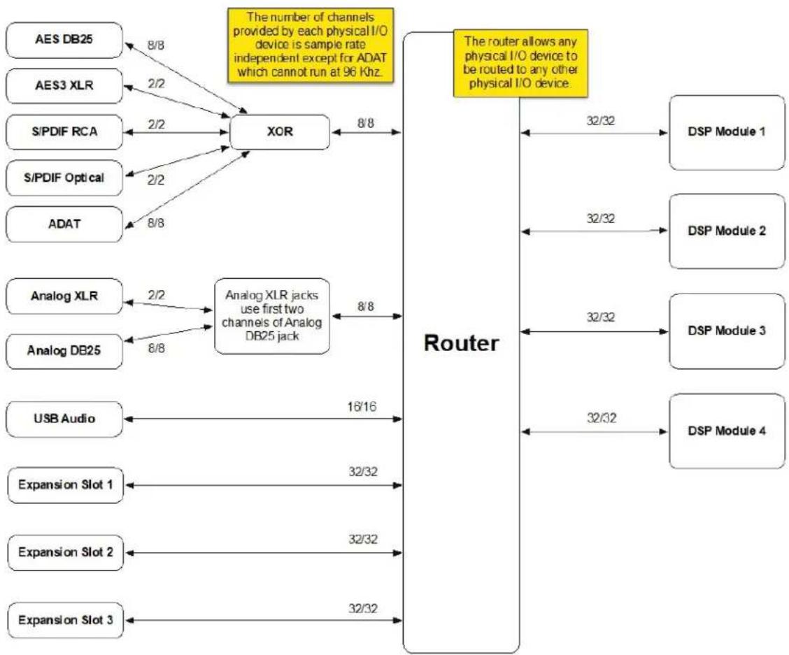
flowchart
graph TD
    A["AES DB25"] -->|8/8| B["XOR"]
    C["AES3 XLR"] -->|2/2| B
    D["S/PDIF RCA"] -->|2/2| B
    E["S/PDIF Optical"] -->|2/2| B
    F["ADAT"] -->|8/8| B
    G["Analog XLR"] -->|2/2| H["Analog XLR jacks use first two channels of Analog DB25 jack"]
    I["Analog DB25"] -->|8/8| H
    J["USB Audio"] -->|16/16| K["Router"]
    L["Expansion Slot 1"] -->|32/32| K
    M["Expansion Slot 2"] -->|32/32| K
    N["Expansion Slot 3"] -->|32/32| K
    B -->|8/8| K
    H -->|8/8| K
    K -->|32/32| L
    K -->|32/32| M
    K -->|32/32| N
    style B fill:#f9f,stroke:#333
    style H fill:#ccf,stroke:#333
    style K fill:#cfc,stroke:#333
B.2. Control Signal Flow

flowchart
graph LR
    A["MIDI Connectors"] --> D["Main CPU"]
    B["USB Audio MIDI"] --> D
    C["Expression Pedals"] --> D
    E["Front Panel App"] --> D
    F["Emote"] --> D
    D --> G["DSP Module 1"]
    D --> H["DSP Module 2"]
    D --> I["DSP Module 3"]
    D --> J["DSP Module 4"]
C. MIDI FUNCTIONALITY
- On the H9000, MIDI is always on and received simultaneously by all five USB ports as well as the MIDI-in DIN connector. The USB-A ports can be connected to any MIDI device, and the USB-B port can be connected to any MIDI host.
- Controller functionalities such as omni-channel, note mode, pitch bend range, etc., are not global. They are made at the controller-mapping level via either the front panel (Section 4.5.1), or Emote (Section 3.3.4.1).
- MIDI Program changes are handled via Scenes, either on the front panel (Section 4.8), or in Emote (Section 3.3.6).
- MIDI feedback can be enabled via either the front panel (Section 2.1.8), or Emote (Section 3.3.8).
- Setting the Tempo Mode to MIDI Clock, either on the front panel (Section 2.1.5), or in Emote (Section 3.3.8), will automatically set the tempo to an incoming MIDI signal (as long as that MIDI signal contains a valid MIDI clock signal). The external MIDI clock signal can arrive either via DIN, or USB-B.
The following action types are available for note-based MIDI controllers:
Velocity Uses the velocity of the selected note as the control value.
Trigger Emits a trigger pulse whenever the note is played.
Toggle Flips between the min and max values when the note is played.
Note Number Uses the whole range of the keyboard, using the note number as the control value.
Note to Hz Uses the whole range of the keyboard, and emits a control value equal to the actual frequency of the note being played.
When using Note to Hz, the "Range" dialog contains 2 range knobs:
- Control Range: Selects the range that controller will respond to from 0-127.
- Parameter Range: Determines how the control range value is applied to the parameter it's affecting. For example, you could use half of the Control Range to sweep the full range of a parameter, or you could use the full Control Range to sweep half the Parameter Range.

Warning
Currently, the H9000 does not transmit or respond to any SysEx messages, and does not output MIDI clock information from its USB ports or MIDI-out DIN connector.

Note
Emote's Functions (Section 3.4.1) may also be used to automate FX Chain and Algorithm parameters via a digital audio workstation.
D. SPECIFICATIONS
Audio Specifications
SNR (A Weighted) THD
44.1 kHz: >114dB 44.1 kHz: <0.002%
48 kHz: >114dB 48 kHz: <0.002%
96 kHz: >114dB 96 kHz: <0.002%
Analog Audio Connections
XLR
Number of Channels 2 inputs, 2 outputs
Pinout Pin #1 is ground, Pin #2 is +phase (hot), Pin #3 is -phase.
DB-25
Number of Channels 8 inputs, 8 outputs
Pinout TASCAM Standard:
https://etide.io/DB-25-Pinout
Digital Audio Connections
USB
Number of Channels 16 inputs, 16 outputs
Supported Sample Rates 96 kHz, 88.2 kHz, 48 kHz, 44.1 kHz
AES (DB-25)
Number of Channels 8 inputs, 8 outputs
Digital Audio Connections
Supported Sample Rates 96 kHz, 88.2 kHz, 48 kHz, 44.1 kHz
Pinout
TASCAM Standard: https://etide.io/DB-25-Pinout
AES (XLR)
Number of Channels 2 inputs, 2 outputs
Supported Sample Rates 96 kHz, 88.2 kHz, 48 kHz, 44.1 kHz
S/PDIF (RCA)
Number of Channels 2 inputs, 2 outputs
Supported Sample Rates 96 kHz, 88.2 kHz, 48 kHz, 44.1 kHz
S/PDIF (Optical)
Number of Channels 2 inputs, 2 outputs
Supported Sample Rates 48 kHz, 44.1 kHz
ADAT (Optical)
Number of Channels 8 inputs, 8 outputs
Supported Sample Rates 48 kHz, 44.1 kHz
Expansion Cards
3 expansion slots for additional optional I/O
Number of Channels 32 inputs, 32 outputs
Supported Sample Rates 96 kHz, 88.2 kHz, 48 kHz, 44.1 kHz
Word Clock (BNC)
Word Clock Input
Termination
75 Ohms, switchable
Digital Audio Connections
Synchronization Sources
Internal, Word Clock, AES XLR, AES DB-25, S/PDIF, ADAT, Expansion Card
Control Connections
Remote Control Inputs
Up to four foot pedals, or four 5v control voltage sources, or six foot switches, or combination
2 14 " TRS inputs. The sleeve is ground reference, the ring is +5 volts (source), and the tip is an analog signal from 0 to 5 volts. Connect either foot switches, foot pedals, or control voltage sources.
Remote Control Outputs
2 isolated relay closures, rated at 30Vdc 1A. Relay #1 is connected between ring and sleeve, while Relay #2 is connected between ring and tip. These connections are electrically isolated from the H9000.
MIDI Connections
5-pin DIN Input, Output, and THRU
USB A and USB B
Physical Dimensions
Size (2U rack space) Net Weight
3.5h x 19w x 12.5d in 14 lbs
8.9h x 48.3w x 31.7d cm 6.4 kg
All specifications are subject to change or improvement at any time without notice or obligation. Please visit https://etide.io/H9000Specs for updated product specifications.
E. TECHNICAL SUPPORT
H9000 Youtube Tutorials
This playlist includes helpful tutorials for setting up and using your H9000: https://etide.io/H9000Tutorials
Eventide Rackmount Forum
The official Eventide forum for the H9000 and other rackmount processors. New H9000 and Emote releases will be announced here periodically: https://etide.io/rackmount-forum
VSig Forum
Support for VSig and the development of H9000 algorithms using VSig: https://etide.io/vsig-preset-forum
H9000 Official Facebook Group
A group where H9000 users can interface with each other and members of the Eventide team: https://etide.io/FB-H9000
H9000 FAQ
Get answers to frequently asked questions and get the most out of your H9000: https://etide.io/H9000FAQs
Contact Eventide Support
If you need technical assistance or product repair, you can email support@eventide.com to submit a ticket to our support department. Please include a detailed report of your problem including your H9000's serial number, firmware version, and what version of Emote you are using. Most inquiries are answered within 24-48 business hours. Note, we are closed on weekends.
© Copyright 2022, Eventide Inc.
- Table Of Contents
- Introduction
- Setup
- Emote
- Getting Started 35
- Overview 38
- Views 43
- Using Emote as a Plug-in 59
- Front Panel Operation
- Hardware
- Firmware
- Expansion Cards
- Legalese
- Startup Sequences
- Signal Flow
- MIDI Functionality
- Specifications
- Technical Support
- Note
- What's in The Box
- Features
- Multiple Quad ARM Processors
- Flexible and Adaptable Effects Structure
- Large Complement of Analog and Digital I/O
- Expandable I/O
- Full Front Panel Control
- Network Connectivity
- Computer Audio Interfacing
- Easy Sharing of FX Chains and Sessions
- Compatibility with VSig3 Editing Software
- Hierarchy
- Session
- FX Chain
- Algorithm
- Parameter
- Setting up Your H9000
- 2.1.1.Info
- System Info
- DSP Modules
- Expansion cards
- Expansion Card Setup
- Name
- Clock
- Clock Source
- Digital Audio Mode
- Clock Status
- Word Clock Termination Status
- Warning
- Tempo
- Off
- Internal
- MIDI Clock
- DAW
- Preferences
- Screen Brightness
- Screen Dim Level
- Display Sleep
- Key Click
- Animations
- Tap LED Timeout
- Bonjour Enabled
- Pedals
- Configuring your Attached Pedal
- Calibrating Your Attached Pedals and Switches
- Control Voltages
- MIDI
- FEEDBACK DIN
- FEEDBACK USB A
- FEEDBACK USB B
- Analog References
- Network
- Ethernet Setup
- Wireless Setup
- Network Configuration
- Creating a Local Access Point
- To create an Access Point:
- Using the H9000 as a Computer Audio Interface
- Changing the USB Audio Sample Rate
- Using the H9000 with macOS
- Using the H9000 With Your Existing Computer Audio Interface
- To Create an Aggregate Device:
- Using the H9000 with Windows
- Getting Started
- Downloading the Installer
- Connection
- Connecting to Emote With an Ethernet Connection
- Connecting the H9000R to Emote With a Wi-Fi Connection
- Switching Networks Using Emote
- Overview
- Menu Bar
- Session
- FX Chain
- Algorithm
- Preset
- Preferences
- View
- Window
- Help
- Tool Bar
- View Options
- Color Blocks
- Globals
- Adding and Removing Sessions
- Adding and Removing FX Chains
- Adding and Removing Algorithms
- Views
- Devices View
- FX Chains View
- Adjusting FX Chain Settings
- Algorithms View
- Editing Algorithm Routing Within an FX Chain
- Configuring Audio Connections
- Parameters View
- MIDI and Controller Mapping
- Combined View
- Scenes View
- Scenes and Trigger Sources
- Creating and Editing Trigger Sources
- Creating and Editing Scenes
- FX Chain Display
- Working with Scenes in Emote
- Direct I/O View
- Setup View
- Using Emote as a Plug-in
- Function Automation
- DAW State Recall
- DAW Tempo Sync
- Getting to know your H9000
- Signal Routing
- Soft Keys
- Sessions
- Session Screen Soft Keys
- New
- Copy
- Delete
- Rename
- Load
- Search
- Preview
- FX Chains
- Configuring the Audio I/O of your FX Chain
- Replacing an FX Chain
- FX Chain Soft Keys
- Add
- Direct I/O
- Presets
- Mix
- Mute/Bypass
- Gain/Levels
- Algorithms
- Algorithms Overview
- Configuring Audio I/O For an Algorithm
- Algorithm Screen Soft Keys
- Add Algorithm
- Move
- Expert Router
- Gain
- List
- Parameters
- Editing Parameters in an Algorithm
- Learn
- Custom Map
- Random
- Functions
- OF TAPS 18 0 - 30
- External Control
- Meters
- Assigning I/O sources to Meters
- More Meters
- Saving and Importing Data
- Saving
- Exporting
- Importing
- Scenes
- Working with Scenes
- Create Map
- Activate
- Scene Maps
- Add Action
- Scene Capture
- Manual
- Edit
- Trigger Sources
- Trigger Source Options
- Load By Number
- Increment/Decrement
- Load Current
- Increment & Load/Decrement & Load
- H9000 Front Panel
- Setup
- Save/Import
- Tap/Scenes
- Cancel (X)
- Jog Wheel
- Mode Buttons
- Power
- USB-A Ports
- Number Pad
- Up/Down Arrows
- CXL
- Return
- H9000R Front Panel
- Power
- Power LED
- Reset Button
- USB-A Ports
- Network Button
- Rear Panel
- Power Connector
- Pedal (x2)
- Relay (x2)
- Ethernet Connector
- USB A Connector
- USB B Connector
- AES/EBU Connector
- AES/EBU 2-channel Input
- MIDI THRU
- Word Clock Input
- Word Clock Output
- Optical Input
- Optical Output
- Expansion A, B, C
- Updating Firmware Using Emote
- Updating Firmware Without an Internet Connection
- Updating Legacy Firmware
- MADI
- MADI Setup
- Source Select
- Tx Format
- Lock Status
- Dante
- Dante Setup
- Clock Sync
- H9000
- Dante
- Sample Rate Match
- Documentation
- Firmware updates
- Pro Tools | HD
- Pro Tools | HD Setup
- Sample Rate
- Interface Mode
- Connection Status
- Loop Master Status
- Clock Control
- Integration
- Using Multiple Pro Tools | HD Expansion cards
- Safety and Warranty
- Safety Information
- Limited Warranty
- Who is Covered Under the Warranty
- When the Warranty Becomes Effective
- Warranty Information
- Who Performs Warranty Work
- Shipping Within the 50 United States
- Shipping Outside the 50 United States
- Federal Communications Commission Statement
- Class A ITE
- CE Class A (EMC)
- A.1. Soft Reset
- A.2. Recovery Mode
- A.3. Factory Reset
- A.4. USB Dump Data
- A.5. USB Self-Test Mode
- B.1. Audio Signal Flow
- B.2. Control Signal Flow
- Audio Specifications
- Analog Audio Connections
- Digital Audio Connections
- Control Connections
- Physical Dimensions
Brand : EVENTIDE
Model : H9000 Madi
Category : Uncategorized