
5M14X1 - Electronic module Daytronic - Free user manual and instructions
Find the device manual for free 5M14X1 Daytronic in PDF.


| Product Type | Digital Signal Conditioner / Indicator |
| Brand | Daytronic |
| Model | 5M14X1 |
| Dimensions (approx.) | 200 x 150 x 80 mm |
| Weight (approx.) | 1.0 kg |
| Power Supply | 100–240 V AC, 50/60 Hz |
| Display | Multi-digit LED or LCD (depending on variant) |
| Input Signal Types | Analog (voltage, current), frequency, thermocouple, RTD |
| Output Options | Relay, analog output, serial data (RS-232/485) |
| Key Functions | Measurement, scaling, alarming, data logging, communication |
| Accuracy | ±0.1% of full scale |
| Operating Temperature | 0°C to 50°C |
| Storage Temperature | -20°C to 70°C |
| Humidity Range | 10% to 90% non-condensing |
| Mounting | Panel mount or DIN rail mount |
| Enclosure Material | Aluminum / ABS plastic |
| Protection Rating | IP20 (front panel), IP40 (enclosure) |
| Maintenance | Clean with a dry, soft cloth; avoid solvents |
| Safety Certifications | CE, RoHS compliant |
| Spare Parts & Repairability | Contact Daytronic support for replacement modules and repairs |
Frequently Asked Questions - 5M14X1 Daytronic
User questions about 5M14X1 Daytronic
0 question about this device. Answer the ones you know or ask your own.
Ask a new question about this device
Download the instructions for your Electronic module in PDF format for free! Find your manual 5M14X1 - Daytronic and take your electronic device back in hand. On this page are published all the documents necessary for the use of your device. 5M14X1 by Daytronic.
USER MANUAL 5M14X1 Daytronic
The Model 5M14(V) is a precision conditioner designed for TC-based temperature measurements requiring high input isolation. With built-in reference-junction compensation, it accepts up to four independent temperature signals from Types E, J, K, N, R, S, and T Thermocouples. All four thermocouple inputs must be of the same type. Sensors may be grounded or ungrounded, in any desired mix. An amplifier-per-channel design with chopper stabilization and active low-pass filtering allows highly responsive, amplified analog signals with or without linearization correction.
For the Model 5M14, the analog output signal is 5 Vdc and the 5M14V is 10 Vdc. These are nominal full scale voltages since the Module is based on a millivolt per degree C value. All setup of the module is accomplished via the front panel configuration switch settings - polarity over-range, TC type, filter setting, extended gain, and linearized or non-linearized output.
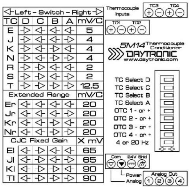
Access switch settings via the front panel of the 5M14 by gently pulling the clear plastic cover (from the bottom side) so the cover rotates open from the top. Use a small tool or finger to place the switches to the left or right position as you face the front of the module. This process can be done with or without power to the unit. Once completed, return the cover to the original position.
Open Thermocouple Detection (OTC)
Can be set per individual TC input to saturate the analog output signal full-scale positive or negative.
Note: when this condition exists the analog output can be as much as 12 Vdc. When an OTC condition occurs, the yellow LED indicator on the front of the module will illuminate.
View of Side Label of the Model 5M14 Thermocouple Module
WARNING
Death, serious injury, or fire hazard could result from improper connection of this instrument. Read and understand this manual before connecting this instrument. Follow all installation and operating instructions while using this instrument.
Connection of this instrument must be performed in compliance with the National Electrical Code (ANSI/NFPA 70-2014) of USA and any additional safety requirements applicable to your installation.
Installation, operation, and maintenance of this instrument must be performed by qualified personnel only. The National Electrical Code defines a qualified person as “one who has demonstrated the skills and knowledge related to the construction and operation of the electrical equipment and installations, and who has received safety training on the hazards involved.”
Qualified personnel who work on or near exposed energized electrical conductors must follow applicable safety related work practices and procedures including appropriate personal protective equipment in compliance with the Standard for Electrical Safety Requirements for Employee Workplaces (ANSI/NFPA 70E-2012) of USA and any additional workplace safety requirements applicable to your installation.
ADVERTENCIA
The following safety precautions must be followed whenever any type of voltage or current connection is being made to the instrument.
Before connecting to electric circuits or pulse initiating equipment, open their related breakers or disconnects. It is recommended NOT TO install any connection of the instrument on live power lines. Only Qualified Service personnel that have demonstrated the abilities and received the proper safety training are capable of connecting to live circuits.
- Connections must be made to the instrument first, then connect to the circuit to be monitored.
- Wear proper personal protective equipment, including safety glasses and insulated gloves when making connections to power circuits.
- Hands, shoes and floor must be dry when making any connection to a power line.
Before each use, inspect all cables for breaks or cracks in the insulation. Replace immediately if defective.
If the equipment is used in a manner not specified in this user's guide, the protection provided by the equipment may be impaired.
Standard Accessories
Standard accessories
The following table lists the 5M standard accessories.
| Description Part Number | |
| Manual & Operating instruction | Resource CD |
5M 14 (V) SPECIFICATIONS
Measurement Range and Resolution: See Table 1, below; switch selected—
Linearization: Internal analog compensated; maximum error: ±0.05°C
Reference-Junction Compensation: Internal, using a built-in precision thermistor
Thermocouple Break Detection (per channel): Selectable, Off-scale negative or positive with front panel indication
Amplifier (per channel)
Normal - Mode Range: ±80 mV operating; ±240 V without instrument damage
Common-Mode Range: ±1000 V (rms) operating and without instrument damage
Common-Mode Rejection Ratio: DC and at 60Hz -154 dB
Input Impedance: Differential: 10 MΩ; Common-Mode: >500 M ohms
Offset: Initial: ±5 μV; vs. Temperature: ±0.1 μV/°C; vs. Time: ±25 ppm/month
Gain Accuracy: ±0.02% of absolute mV input range of -10 to +80 mV
Gain Stability : vs. Temperature: ±25 ppm/°C; vs. Time: ±25 ppm/month
Filter (per module): 3-pole modified Butterworth; 3 dB down at 4 Hz or 20 Hz; selectable
Step-Response Settling Time (Full-Scale Output @ 4 Hz)
To 1% of final value: 0.450 sec; (0.060 sec @ 20 Hz)
To 0.1% of final value: 0.600 sec; (0.080 sec @ 20 Hz)
To 0.02% of final value: 0.750 sec; (0.125 sec @ 20 Hz)
Total Accuracy : 0.05% full scale, including linearzaton, compensation and amplification
Analog Output : Reference Table 1 below, millivolt or fixed gain per Degree C, selectable
Power Supply: 24 Vdc +/- 10% regulated; 110 mA nominal, 150 mA max.
Operating Temperature: -10 to +70 Degrees C, 5 to 95% relative humidity, non-condensing
Table 1 Thermocouple Ranges for the Model 5M14 (V)
| TC Type | Standard Range | mV/ Degree C | 5 Vdc Unit/ FS | 10 Vdc Unit/ FS |
| E | -200°C to +1000°C | 5.00 mv/°C | 5.000 Vdc | 10.000 Vdc |
| J | -200°C to +1200°C | 4.00 | 4.800 | 9.600 |
| K | -200°C to +1372°C | 4.00 | 5.488 | 10.976 |
| N | -180°C to +1300°C | 4.00 | 5.200 | 10.400 |
| R | -50°C to +1768°C | 2.00 | 3.536 | 7.072 |
| S | -50°C to +1768°C | 2.00 | 3.536 | 7.072 |
| T | -200°C to +400°C | 12.50 | 5.000 | 10.000 |
| TC Type | Reduced TC Range | mV/ Degree C | 5 Vdc Unit/ FS | 10 Vdc Unit/ FS |
| Jr | -200°C to +250°C | 20.00 mv/°C | 5.000 Vdc | 10.000 Vdc |
| Er | -200°C to +250°C | 20.00 | 5.000 | 10.000 |
| Kr | -200°C to +250°C | 20.00 | 5.000 | 10.000 |
| Nr | -180°C to +250°C | 20.00 | 5.000 | 10.000 |
| TC Type | Non-Linearized CJC Range | mV Gain/ TC output | 5 Vdc Unit/ FS | 10 Vdc Unit/ FS |
| JI | -200°C to +1000°C | 65.0 | 4.964 Vdc | 9.928 Vdc |
| EI | -200°C to +1200°C | 65.0 | 4.521 | 9.042 |
| KI | -200°C to +1372°C | 90.0 | 4.940 | 9.880 |
| NI | -180°C to +400°C | 90.0 | 1.878 | 3.757 |
ref @ 0 degree C
2 TRANSDUCER CONNECTIONS
The Model 5M14(V) I/O CONNECTIONS are via non-removable screw terminals which will accept wire sizes from AWG 12 to 26. NOTE: unused thermocouple inputs should have their individual channels + and - terminals shorted together to prevent over-range LED light indication. Thermocouple wire should be directly attached to its corresponding screw terminals - never solder or use copper wire extensions which will cause cold junction compensation errors. Table 2 denotes screw terminal assignments.
Table 2 Model 5M14 Pin Assignments
| I/O Connector Conditioner ConditionerPin Screw Channel Line | |||
| Number | Terminal | Number | Function |
| Top Rear 1 1(+) 1 +SIGNAL TC Input | |||
| Top Rear 2 2(-) 1 -SIGNAL TC Input | |||
| Top Rear 3 3(+) | 2 | +SIGNAL TC Input | |
| Top Rear 4 4(-) | 2 -SIGNAL TC Input | ||
| Top Front 1 | 1(+) | 3 | +SIGNAL TC Input |
| Top Front 2 | 2(-) 3 -SIGNAL TC Input | ||
| Top Front 3 | 3(+) | 4 | +SIGNAL TC Input |
| Top Front 4 | 4(-) | 4 | -SIGNAL TC Input |
| Bottom Front 1 | 1 | all | +SIGNAL Output |
| Bottom Front 2 | 2 | n/a | +SIGNAL Output |
| Bottom Front 3 | 3 | n/a | +SIGNAL Output |
| Bottom Front 4 | 4 | all | +SIGNAL Output |
| Bottom Rear 1 | 1 | 1 | Analog Common |
| Bottom Rear 2 | 2 | 2 | Power Common |
| Bottom Rear 3 | 3 | 3 | 24 Vdc Power |
| Bottom Rear 4 | 4 | 4 | Shield |
Fig. 1 Model 5M14 Transducer Cabling

flowchart
graph TD
    A["Top Thermocouple Input Connectors (viewed from front)"] --> B["+ SIGNAL"]
    A --> C["- SIGNAL"]
    A --> D["+ SIGNAL"]
    A --> E["- SIGNAL"]
    F["Front Terminals"] --> G["TC1 TC2"]
    F --> H["TC3 TC4"]
    I["Bottom Power & Signal Connectors"] --> J["Analog Out"]
    K["Analog Common"] --> L["A com P com 24V 1 2 3 4"]
    M["Power Common"] --> N["24 Vdc Power Input"]
    O["SHIELD"] --> P["+ SIGNAL"]
    O --> Q["- SIGNAL"]
3 CALIBRATION
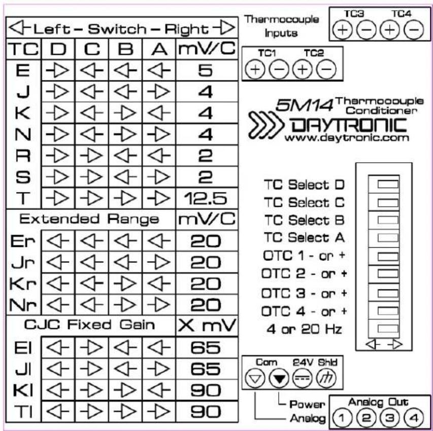
The Model 5M14(V) does not require field calibration. Front panel selector switches, as shown below, will enable the correct linearization and cold junction temperature compensation to the thermocouple connected to the unit. All four thermocouples will be conditioned and linearized for the thermocouple type selected. Note: Depending on the switch selection, the conditioned output of the thermocouple signal(s) will be -1) Normal gain through-out the thermocouple's temperature specification to NIST tables. 2) Extended gain if the user desires amplification in a restricted temperature range. 3) Non-linearized which enables the Cold Junction Compensation and gain amplification only. In this mode it is expected that the external readout device connected to the 5M14(V) will perform the correct linearization operation for the application and connected thermocouple sensor(s).

Switch 1 - TC Select D - selects thermocouple type, see chart 1
Switch 2 - TC Select C - selects thermocouple type, see chart 1
Switch 3 - TC Select B - selects thermocouple type, see chart 1
Switch 4 - TC Select A - selects thermocouple type, see chart 1
Switch 5 - OTC 1 - selects positive or negative open thermocouple on channel 1
Switch 6 - OTC 2 - selects positive or negative open thermocouple on channel 2
Switch 7 - OTC 3 - selects positive or negative open thermocouple on channel 3
Switch 8 - OTC 4 - selects positive or negative open thermocouple on channel 4
Switch 9 - Filter - selects 4 Hz or 20 Hz for all four thermocouple analog signals
OTC - indicates an open thermocouple condition, analog signal saturates positive or negative pending switch condition of associated channel
Power - indicates the power input voltage is ON
TC Switch Select Chart
Dimensions

Housing height : 114.5 mm Housing depth : 99 mm Housing width : 22.5 mm
Product Warranty and Repair
Daytronic Corporation warrants its products to be free from defects in material and workmanship, under normal and proper use in accordance with our instructions, for the period of time specified below. Our liability under such warranty or in connection with any other claim relating to the products shall be limited to, at our option, the repair or replacement of any products or parts or components thereof which are returned to us freight prepaid and which are defective in material or workmanship or the refund of the purchase price to the Buyer.
ANY PRODUCT FOUND TO BE DAMAGED THROUGH CUSTOMER NEGLIGENCE OR MIS-USE MAY BE EXCLUDED FROM ANY AND ALL POLICIES CONTAINED IN THIS DOCUMENT.
ALL EQUIPMENT TO BE REPAIRED OR REPLACED UNDER WARRANTY MUST BE RETURNED TO THE FACTORY. Before returning a product or products for any reason, the customer must call Daytronic Customer Support Services at (937) 866-3300 to request a RETURN MATERIAL AUTHORIZATION (RMA). Once the customer has provided the necessary information and has been assigned a specific RMA, the product(s) in question may be returned to Daytronic by shipping it
Daytronic Corp., 1000 New Durham Road, Edison, New Jersey 08818
Daytronic Customer Service: 1-800-668-4745 service@daytronic.com

DAYTRONIC
Daytronic Corporation Dayton OH USA Tel 937-293-2566 Fax 937-293-2586
www.daytronic.com


Brand : Daytronic
Model : 5M14X1
Category : Electronic module