
5M64 - Electronic module Daytronic - Free user manual and instructions
Find the device manual for free 5M64 Daytronic in PDF.


| Product Type | Data Acquisition System |
| Brand | Daytronic |
| Model | 5M64 |
| Dimensions (L x W x H) | 12.0 x 6.0 x 4.0 inches (30.5 x 15.2 x 10.2 cm) |
| Weight | 2.5 lbs (1.13 kg) |
| Power Supply | 120 V AC, 60 Hz, 0.5 A |
| Channels | 8 analog input channels |
| Input Type | Voltage, current, thermocouple, RTD |
| Display | 4-line backlit LCD, 16 characters per line |
| Communication | RS-232 and USB 2.0 |
| Data Logging | Internal memory for 100,000 readings |
| Sample Rate | Up to 100 samples per second per channel |
| Accuracy | ±0.1% of reading ±1 digit |
| Operating Temperature | 0°C to 50°C (32°F to 122°F) |
| Storage Temperature | -20°C to 70°C (-4°F to 158°F) |
| Protection Rating | IP40 (front panel) |
| Maintenance | Clean with a dry cloth; no user-serviceable parts inside |
| Safety | CE, UL listed; overvoltage protection on inputs |
| Spare Parts | Power supply, cables, and sensor connectors available from Daytronic |
| Repairability | Factory repair only; contact Daytronic support |
Frequently Asked Questions - 5M64 Daytronic
User questions about 5M64 Daytronic
0 question about this device. Answer the ones you know or ask your own.
Ask a new question about this device
Download the instructions for your Electronic module in PDF format for free! Find your manual 5M64 - Daytronic and take your electronic device back in hand. On this page are published all the documents necessary for the use of your device. 5M64 by Daytronic.
USER MANUAL 5M64 Daytronic
The Model 5M64 is a single-channel DIN Mount instrument which is an easily configured, rugged, analog based signal conditioner made to operate with traditional DC sensor sources, such as string potentiometers, DC LVDTs and other sensors to measure force, pressure, torque, displacement and related measurements. The Model 5M64 has an extremely wide DC signal input range with user selectable gain, zero and analog output making it adaptable to any sensor application that requires stable, repeatable and noise free analog signals for control or data acquisition requirements.

Model 5M64 DC Voltage Module
Access switch settings via the front panel of the 5M64 by gently pulling the clear plastic cover (from the top side) so the cover rotates open from the bottom. Use a small tool or finger to place the switches to the left or right position as you face the front of the module. This process can be done with or without power to the unit. Once completed, return the cover to the original position.
4-20mA Input Operation
The Model 5M64 contains a precision input shunt resistor for mA input as indicated by the resistor symbol on input pin 3.
View of Side Label of the Model 5M64 DC Voltage Module
WARNING
Death, serious injury, or fire hazard could result from improper connection of this instrument. Read and understand this manual before connecting this instrument. Follow all installation and operating instructions while using this instrument.
Connection of this instrument must be performed in compliance with the National Electrical Code (ANSI/NFPA 70-2014) of USA and any additional safety requirements applicable to your installation.
Installation, operation, and maintenance of this instrument must be performed by qualified personnel only. The National Electrical Code defines a qualified person as “one who has demonstrated the skills and knowledge related to the construction and operation of the electrical equipment and installations, and who has received safety training on the hazards involved.”
Qualified personnel who work on or near exposed energized electrical conductors must follow applicable safety related work practices and procedures including appropriate personal protective equipment in compliance with the Standard for Electrical Safety Requirements for Employee Workplaces (ANSI/NFPA 70E-2012) of USA and any additional workplace safety requirements applicable to your installation.
ADVERTENCIA
The following safety precautions must be followed whenever any type of voltage or current connection is being made to the instrument.
Before connecting to electric circuits or pulse initiating equipment, open their related breakers or disconnects. It is recommended NOT TO install any connection of the instrument on live power lines. Only Qualified Service personnel that have demonstrated the abilities and received the proper safety training are capable of connecting to live circuits.
- Connections must be made to the instrument first, then connect to the circuit to be monitored.
- Wear proper personal protective equipment, including safety glasses and insulated gloves when making connections to power circuits.
- Hands, shoes and floor must be dry when making any connection to a power line.
Before each use, inspect all cables for breaks or cracks in the insulation. Replace immediately if defective.
If the equipment is used in a manner not specified in this user's guide, the protection provided by the equipment may be impaired.
Standard Accessories
Standard accessories
The following table lists the 5M standard accessories.
| Description Part Number | |
| Manual & Operating instruction | Resource CD |
5M64 SPECIFICATIONS
Measurement Range: Adjustable 0.50 mV to 50.0 V; nominal full-scale; 4-20ma
Transducer Types: Any transducer producing DC Voltage (0.05 to 50 VDC) or 4-20ma signals Excitation: 10 VDC (+/- 5 VDC @ up to 70ma)
Power Supply : 11 - 28 Vdc regulated; 2 watts max.
Analog Output: selectable; ±0 to 5, ±0 to 10 Vdc, 4-12-20 or 4-20mA (20% over-range, voltage only)
Operating Temperature : -10 to +70 Degrees C, 5 to 95% relative humidity, non-condensing
Accuracy: Limited only by calibration accuracy.
Amplifier
Common - Mode Range : ± input range depended; see table 2.0
Common - Mode Rejection Ratio : - 60 dB @ 1/2 excitation
Input Impedance: Differential and Common-Mode > 10,000 MΩ
Offset : user adjustable; vs. Temperature: ±30 ppm /°C; vs. Time: ±10 ppm/month
Gain Accuracy: Limited only by calibration accuracy
Gain Stability: vs. Temperature: ±30 ppm/°C; vs. Time: ±10 ppm/month
Linearity: better than ± 0.03% of full scale
Filter: 3-pole modified Butterworth; 3 dB down at 10 Hz, 100 Hz or 1kHz; selectable Step-Response Settling Time (Full-Scale Output @ 10 Hz)
To 1% of final value: 0.07 sec; (0.007 sec @ 100 Hz) (0.0007 sec @ 1 kHz)
To 0.1% of final value: 0.09 sec; (0.009 sec @ 100 Hz) (0.0009 sec @ 1 kHz)
To 0.02% of final value: 0.10 sec; (0.010 sec @ 100 Hz) (0.0010 sec @ 1 kHz)
Dimensions
Dimensional drawing
![Housing height [A] : 114.5 mm Housing depth [B] : 99 mm Housing width [C] : 22.5 mm 36 22 3, 2,2 7, 0.3 20 DIN Power Connection (top) 5 N/C 4 N/C 3 N/C 2 POWER COMMON 1 DC POWER](/content/2026/05/1012561/images/11dce242723d2f850a7a0e189f4d79e4f1fb421483b5fc3a54f9ca4191f833da.jpg)
Optional DIN Power Rail Connector Model 5M-PCON
2
TRANSDUCER CONNECTIONS
The Model 5M64 I/O CONNECTIONS are via non-removable screw terminals which will accept wire sizes from AWG 12 to 26. NOTE: The recommended transducer cabling would be individually shielded, twisted pair - wired as indicated (Fig. 1)
Table 2 denotes screw terminal assignments
Table 1 Model 5M64 Pin Assignments
| I/O Connector Conditioner | |||
| Pin Number | Screw Terminal | Terminal Label | Line Function |
| Top Rear 1 | 1 | + EXC | + EXCITATION |
| Top Rear 2 2 COMM | EXCITATION COMMON | ||
| Top Rear 3 | 3 - EXC | - EXCITATION | |
| Top Rear 4 | 4 | N/A | NOT USED |
| Top Front 1 | 1 | + SIG | + SIGNAL Input |
| Top Front 2 | 2 | - SIG | -SIGNAL Input |
| Top Front 3 | 3 | SHUNT | CURRENT SHUNT |
| Top Front 4 | 4 | // | SHIELD |
| Bottom Front 1 | 1 | Ano Out | ANALOG Output |
| Bottom Front 2 | 2 | N/C | NO CONNECT |
| Bottom Front 3 | 3 | CMF | COMMON MODE FAULT * |
| Bottom Front 4 | 4 | N/C | NO CONNECT |
| Bottom Rear 1 | 1 | Acom | Analog Common |
| Bottom Rear 2 | 2 | Pcom | Power Common |
| Bottom Rear 3 | 3 | 24 V | 24 Vdc Power |
| Bottom Rear 4 | 4 | // | SHIELD |
* Common Mode Fault Logic output - output true when fault condition exist
Fig. 1 Model 5M64 Transducer Cabling (Non-Removable Screw Terminals)


Transducer Field Connector - Current Mode

Transducer Field Connector - Current Mode

3. CALIBRATION
This section contains the instructions for calibrating the 5M64. Included is a functional description of the instrument front-panel (see Figure 2). To perform calibration, proceed as follows with the sensor or calibration standard connected.
(a) Turn power ON to the 5M64 DC Power input terminal (11 to 28 Vdc input) The front-panel indicator should light green to indicate the application of dc power. Allow 10 minutes of warmup for stabilization of transducer characteristics.
(b) Set the Coarse Span controls to the marked label position (Min>).
(c) Position the front panel switches to the desired settings for the application. Refer to Fig. 2 for details. Connect readout device (i.e. voltmeter) to ANO & A Common.
(d) With the input signal position at "zero", adjust the Fine Zero control until the desired analog output is achieved. Depending on your input selection the "zero" input could be near zero volts DC, or 4 mA or 12m pending front panel switch locations.
(e) Apply a known voltage or current input value which is greater than one half of full scale in the positive direction. Adjust the Coarse Span to obtain your nominal full scale analog output of th 5M64 Module. Use Fine Span control to adjust the output the analog output to a precise value required.
(f) Repeat step (e) as needed to obtain analog output precision. Note that any Span (gain) adjustments will effect the Zero (balance) value.
When completed, replace the plastic front cover to its original position and ensure connections and proper shielding to the module, and to the DIN rail to which the 5M64 is attached, are correct.
Fig. 2 Model 5M64 Front Panel Settings and Indicators

Switch 1 - Mode - selects current (I) or voltage analog output
Switch 2 - Volts - selects +/- 5 or +/- 10 Vdc when mode is voltage
Switch 3 - Current - selects 4-12-20 or 4-20mA when mode is current
Switch 4 - Filter - selects 1 kHz or 100 Hz at 3 db, for 100 Hz switch 5 must be set to the right
Switch 5 - Filter - selects 10 Hz or 100 Hz at 3 db, for 100 Hz switch 4 must be set to the right
Switch 6 - Range A - selects 0.05V-0.5V or 0.5-5.0V
Switch 7 - Range B - selects 5.0-50.0V or 0.5-5.0V
Switch 8 - Input - selects 4-20ma or Voltage
Switch 9 - Input - selects 4-12-20ma or Voltage
Fine Zero - 16 turn potentiometer for fine zero balance control
Coarse Span - 16 position switch adjustment for stepped gain control with default calibration indicator
Fine Span - 16 turn potentiometer for fine gain - span control
Over Range - Yellow: analog output is 2% greater than mode selected Red: Common mode has exceed input limit
Power - indicates the power input voltage is ON
Table 2 Model 5M64 Common Mode Range Levels
| Range(VDC,ma f.s.) | C-M Range(+/- V) | |
| 5M64 Ranges | 0.050 - 0.500 5 | |
| 0.500 - 5.000 | 50 | |
| 5.000 - 50.00 | 50 | |
| 4.00 - 20.00 ma | 50 | |
| 4.00 - 12 - 20.00 ma | 50 |
Common Mode: Is the voltage level at which the input signal can be "floating" from earth common which the 5M64 can function properly. If this level is exceeded, the Over-Range indicator will illuminate Red and the the connector labelled "CMF" will go true, giving the user a remote status of the Common-Mode condition of the 5M64 Module.
4. VERIFICATION OF NORMAL OPERATION
It is the purpose of this section to aid the user in determining, in the event of a malfunction of which the Model 5M64 is suspected of contributing, whether the instrument is functioning normally or whether it is the source of the observed trouble. In the event the unit requires repair, the user may also contact the factory Service Department or the local Daytronic Representative for assistance. Daytronic service information is located on the last page of this document.
If the instrument is suspected of faulty operation, perform the following steps.
(a) If the unit is totally inoperational (front-panel power indicator does not light), check the primary power input terminals for proper connection. Input power can be from 11 to 28 Vdc and will draw less than 2 watts. If properly connected, the front panel Green LED will be illuminated. Before reapplying power, visually inspect the power supply and the input power connections for any discrepancy which could have caused the overload.
(b) If the input has some preloading offset, the Zero controls may not allow successful zeroing of the instrument output. The fine zero control is limited to +/- 2.0 % of the full scale value. Check or change the input level to conform to this requirement. If this is verified and the zero adjustment does not function. Remove the input lines and place a "shorting" jumper between the + and - Signal Inputs to the Module.
(c) With the short in place, re-adjust the fine zero control and measure the analog output for change. If there is none, then the module is suspect; if there is change on the output, check the incoming signal and connections.
(d) Constant Red or Yellow LED Over-Range indication. This indicates an input magnitude of the signal that is greater than 20% of the adjusted range of the module or there is a Common Mode level outside the proper operation of the unit. Remove, the input from the Module. If the LED goes out, blank, then the input to the conditioner is superspect. If the LED stays lite, then the Module is suspect. Double check this by shorting the + and - Signal input leads to the Module. The Over-Range LED should not turn on. If it does, contact the factory service group.
(e) No signal change on the output. If you are using the Module's excitation power to excitate the sensor, check for proper voltage output (+ & - 5 Vdc). If this is not correct, disconnect the sensor from the excitation supplies and re-check. If the voltage level comes to +/- 5 Vdc (10 Vdc across the terminal) the the sensor maybe drawing too much current for the Module to accommodate and an external power supply maybe necessary.
Tech Tip on use of wide range settings for the DC Voltage Conditioner
Due to multiple amplifier stages within the instrument, attention to the proper gain setting and understanding of the sensor inputs should be reviewed to produce a linear-amplified analog output signal and display reading.
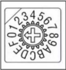
The wide span – gain control (as shown in the front panel diagram) has 16 positions to amplify the incoming signal by incremental steps. Each step is positioned so the Fine Span potentiometer control overlaps each step to provide a continuous linear gain of the signal from 50 mVdc to 50Vdc full scale. Below is a table of each wide gain steps, indicating the nominal low and high input signal range per position – full scale in VDC to the meter. Slight variations of the listed values will be noticed due to tolerance specifications of the analog control adjustments.
Wide Span Control table for Low, Medium and High Input DC Voltage adjustment per Front panel Range selection
| Range Switch 6 & 7 | Input Range | 0.050 - 0.500 | 0.50 - 5.00 | 5.0 - 50.0 | ||||||
 Coarse Span Coarse Span | Min Max | Min Max | Min Max | |||||||
| F 0.045 | 0.054 0.45 | 0.55 4.5 | 5.4 | |||||||
| E 0.052 | 0.063 0.53 | 0.64 5.2 | 6.3 | |||||||
| D 0.061 | 0.073 0.62 | 0.74 6.1 | 7.3 | |||||||
| C 0.071 | 0.085 0.72 | 0.86 7.2 | 8.6 | |||||||
| B 0.083 | 0.100 0.84 | 1.01 8.3 | 10.0 | |||||||
| A 0.097 | 0.116 0.98 | 1.17 9.7 | 11.7 | |||||||
| 9 0.113 | 0.135 1.14 | 1.37 | 11.3 | 13.6 | ||||||
| 8 0.131 | 0.158 1.33 | 1.59 | 13.2 | 15.8 | ||||||
| 7 0.153 | 0.184 1.55 | 1.86 | 15.5 | 18.6 | ||||||
| 6 0.179 | 0.214 1.80 | 2.16 | 18.1 | 21.6 | ||||||
| 5 0.208 | 0.250 2.10 | 2.52 | 21.1 | 25.2 | ||||||
| 4 0.243 | 0.291 2.45 | 2.94 | 24.5 | 29.3 | ||||||
| 3 0.283 | 0.339 2.85 | 3.42 | 28.6 | 34.2 | ||||||
| 2 0.330 | 0.395 3.32 | 3.99 | 33.3 | 39.9 | ||||||
| 1 0.384 | 0.461 3.87 | 4.65 | 38.8 | 46.4 | ||||||
| 0 0.447 | 0.537 4.47 | 5.37 | 45.3 | 54.1 | ||||||
| ← Left | Switch | Right → |
| CURRENT | 1 OUTPUT MODE | VOLTS |
| 10.0 Vdc | 2 VOLTS | 5.0 Vdc |
| 4-12-20 mA | 3 CURRENT | 4-20 mA |
| 1 kHz | 4 FILTER | 100 Hz |
| 10 Hz | 5 FILTER | 100 Hz |
| .05-0.50 Vdc | 6 RANGE A | 0.50-5.0 Vdc |
| 5.0-50.0 Vdc | 7 RANGE B | 0.50-5.0 Vdc |
| 4-20 mA | 8 INPUT MODE | VOLTAGE |
| 4-12-20 mA | 9 INPUT MODE | VOLTAGE |
Front Panel Switches #6 and #7 - RANGE A and RANGE B are used to set the Wide Input Signal Range of the conditioner. The 16 Position rotary switch - Course Span will select the appropriate gain within this Range. Use the Fine Span potentiometer adjustment to tune the analog output signal to the desired level.
Product Warranty and Repair
Daytronic Corporation warrants its products to be free from defects in material and workmanship, under normal and proper use in accordance with our instructions, for the period of time specified below. Our liability under such warranty or in connection with any other claim relating to the products shall be limited to, at our option, the repair or replacement of any products or parts or components thereof which are returned to us freight prepaid and which are defective in material or workmanship or the refund of the purchase price to the Buyer.
ANY PRODUCT FOUND TO BE DAMAGED THROUGH CUSTOMER NEGLIGENCE OR MIS-USE MAY BE EXCLUDED FROM ANY AND ALL POLICIES CONTAINED IN THIS DOCUMENT.
ALL EQUIPMENT TO BE REPAIRED OR REPLACED UNDER WARRANTY MUST BE RETURNED TO THE FACTORY. Before returning a product or products for any reason, the customer must call Daytronic Customer Support Services at (937) 866-3300 to request a RETURN MATERIAL AUTHORIZATION (RMA). Once the customer has provided the necessary information and has been assigned a specific RMA, the product(s) in question may be returned to Daytronic by shipping it
Daytronic Corp., 1000 New Durham Road, Edison, New Jersey 08818
Daytronic Customer Service: 1-800-668-4745 service@daytronic.com


Brand : Daytronic
Model : 5M64
Category : Electronic module