
140 - Audio processor DBX - Free user manual and instructions
Find the device manual for free 140 DBX in PDF.


| Product Type | Audio Processor (Compressor/Limiter) |
| Model | 140 |
| Brand | DBX |
| Channels | 2 (Stereo or Dual Mono) |
| Dimensions (H x W x D) | 1.75 x 19 x 6 inches (44 x 483 x 152 mm) |
| Weight | 2.5 kg (5.5 lbs) |
| Power Supply | 100–240 VAC, 50/60 Hz, 20 W |
| Frequency Response | 20 Hz – 20 kHz, ±0.5 dB |
| Input Impedance | 10 kΩ (balanced) |
| Output Impedance | 50 Ω (balanced) |
| Maximum Input Level | +20 dBu |
| Maximum Output Level | +20 dBu |
| Dynamic Range | >110 dB (A-weighted) |
| THD + Noise | <0.01% typical |
| Primary Functions | Compression, Limiting, De-essing, Peak Limiting, Output Gain |
| Controls | Threshold, Ratio, Attack, Release, Gain, Bypass, Stereo Link |
| Indicators | LED gain reduction meter, Power LED, Bypass LED |
| Connectors | XLR balanced input and output (left/right) |
| Rackmount | 1U standard rackmount, ears included |
| Operating Temperature | 0°C to 40°C (32°F to 104°F) |
| Humidity | 0% to 90% non-condensing |
| Cleaning | Wipe with a dry soft cloth; do not use solvents |
| Safety | Class I device, use grounded power outlet |
| Spare Parts & Repairability | No user-serviceable parts; contact authorized service center |
| Accessories Included | Power cord, user manual |
Frequently Asked Questions - 140 DBX
User questions about 140 DBX
0 question about this device. Answer the ones you know or ask your own.
Ask a new question about this device
Download the instructions for your Audio processor in PDF format for free! Find your manual 140 - DBX and take your electronic device back in hand. On this page are published all the documents necessary for the use of your device. 140 by DBX.
USER MANUAL 140 DBX
The dbx Model 140 simultaneous encode/decode broadcast noise reduction system is a two-channel compressor/expander providing a minimum of 30 dB broadband audio noise reduction with a 10 dB increase in a system headroom. The two channels feature independent encode and decode circuitry.
In the record mode, the system compresses the input signal by a 2:1 ratio, linear in decibels over a 100 decibel range. Upon playback, the circuitry produces an exact mirror image 1:2 expansion of the encoded signal.
True RMS level sensing insures perfect encode/decode tracking for accurate transient response irrespective of phase shifts in the transmission or storage medium. There is no audible breathing, pumping or other coloration of the sound with this encode/decode system, and there are no pilot tones or routine calibration procedures necessary for its use.
The dbx system eliminates tape hiss in recording and prevents the noise build-up normally encountered in transferring information from one recorded medium to another; it does not remove noise present in the original signal. The dbx 140 noise reduction system is built to professional standards using the latest advances in circuit design and technology and is fully warranted (parts and labor) for two years.
APPLICATION
For recording live announce or studio productions on cartridges, the dbx Model 140 noise reduction system completely eliminates the tape hiss which usually accompanies the recording process. This allows spots or other program content originating on cartridges (historically the noisiest link in the broadcast chain) to approach the sound quality of live broadcasting.
When used for transfer of program material to cartridge from other recorded sources, the dbx encoding prevents any additional noise build up beyond that contained in the original material.
The result of dbx encoding is to minimize the audible quality differences between cart playback and live announce or between one cart and another. dbx encoding also minimizes the effect of "automated sound" and allows a fully automated station to approach live sound quality.
Non-cartridge-related broadcast uses for the dbx 140 system include improving the signal-to-noise ratio of reel-to-reel studio recorders, eliminating hiss from TV audio tracks and cleaning up noisy full-frequency land lines or microwave links from the studio to the transmitter. A modest investment in dbx 140 noise reduction units can protect a much larger investment by prolonging the useful life of major studio equipment and installations that might not otherwise meet contemporary performance standards.
The dbx 140 may also be used as a playback-only device to decode dbx encoded discs or tapes for broadcast.
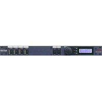
FRONT PANEL LAYOUT

Trim adjustments to match 140 operation to the levels with which it will operate. These trims are for operating convenience and will not effect the encode/decode linearity in any way.
HOW TO USE THE FUNCTION SELECT BUTTONS ON YOUR 140 (PUSH ONLY ONE BUTTON AT A TIME)
| WHAT YOU PUSH | WHAT YOU GET | ||
| TAPE | BYPASS | dbx DISC | |
 | dbx ENCODED PROGRAMProgram coming FROM CONSOLE OUTPUTS will be encoded and sent TO RECORDER INPUTS. | ||
 | dbx DECODED PROGRAMProgram coming FROM RECORDER OUTPUTS will be decoded. and sent TO CONSOLE OUTPUTS. | ||
 | NO SIGNAL PROCESSING FROM RECORDERProgram coming FROM CONSOLE OUTPUTS will be sent directly TO RECORDER INPUTS, and program comingFROM RECORDER OUTPUTS will be sent directly TOCONSOLE INPUTS with no encoding or decoding | ||
 | dbx DISC/SOURCE DECODINGProgram coming FROM CONSOLE OUTPUTS will be internally connected to the terminals labelled FROM RECORDER OUTPUTS, then decoded and fed TO CONSOLE INPUTS. The encoded dbx disc program fed FROM CONSOLE OUTPUTS will also be fed TO RECORDER INPUTS, in encoded form. | ||
REAR PANEL LAYOUT
Connect audio output (line level) from mixing console to these terminals.
Connect audio output (line level) from tape machine or transmission line to these terminals.

AC Line Cord connects the 140 to 117 VAC, 50 or 60 HZ AC power source only. Models for use with other sources are available outside the continental United States. Contact factory for information.
NOTE: The 140 is not equipped with a power ON/OFF switch but is designed instead to be connected to the master switched AC outlet of your audio system. Since the 140 draws very little AC power, it can be plugged into an unswitched AC outlet and left ON all the time.
TYPICAL SIGNAL CONNECTIONS - INPUT AND OUTPUT
Input Connections (FROM CONSOLE OUTPUTS, FROM RECORDER OUTPUTS)
For balanced or floating lines, connect the signal leads to the (+) and (-) terminals, and the shield to the chassis ground ( 12 ) terminal. For unbalanced lines, connect the signal high lead to the (+) terminal and jumper the (-) and chassis ground ( 12 ) together for connection of the shield. When using an unbalanced connection, reversing the (+) and (-) input terminals will cause the output signal to be 180^ out of phase (reverse polarity) relative to the input signal. The Model 140 input impedance is 75,000 ohms when connected in the balanced configuration but is 54,000 ohms when connected in the unbalanced configuration.
Output Connections (TO CONSOLE INPUTS, TO RECORDER INPUTS)
The output of the dbx 140 is designed to feed balanced or unbalanced 600 ohm or greater loads. The output stage is single ended so that in normal operation the (-) signal output terminal is internally connected to the (±) terminal. When the system bypass is engaged, the signal inputs are directly connected to the signal outputs. For maximum hum rejection, avoid common grounding at the input and output (avoid "double-grounding"). One grounding method that usually works is to ground the shield at the 140's output (±) terminal and also ground it at the input of the following device. Do not connect the shield at the 140's input (±) terminal. Leave the input shield connected only to the output of device feeding the 140.
SETTING THE LEVEL ADJUST CONTROLS
The dbx Model 140 is factory calibrated for nominal input and output levels of 1 Volt. The three screwdriver adjustable LEVEL ADJUST controls on the front panel are provided to maintain similar input and output levels in encode and decode modes and to optimize level matching between the dbx 140 and the rest of your system for the best headroom and lowest noise. Each control adjusts two channels simultaneously so proper stereo balance is maintained.
Before making adjustments, make sure your tape machine or transmission line is adjusted or aligned according to the manufacturer's specifications. Connect the 140 to your system using inputs and outputs as shown.
RECORD Level Adjustment
- Depress BYPASS button on 140.
- Run a 1 KHz tone through your console so that the meters indicating the console output levels to the 140 read at nominal operating levels (0 VU).
- Adjust tape recorder input gain so that the tape recorder meters read 0 VU.
- Depress TAPE button. Adjust 140 RECORD LEVEL ADJUST, if necessary, so that tape recorder meters again read 0 VU.
PLAY Level Adjustment
- Depress BYPASS button on 140.
- Using the 1 KHz tone on the appropriate alignment tape, adjust your tape recorder output gain so that the meters indicating the recorder output levels to the 140 read at nominal operating levels (0 VU).
- Adjust console input gain so that the meters indicating the output levels from the 140 read 0 VU.
- Depress TAPE button. Adjust the 140 PLAY LEVEL ADJUST, if necessary, so that console meters indicating the output levels from the 140 again read 0 VU.
DISC Level Adjustment
-
If 140 is connected to a tape recorder, put recorder in SOURCE mode. (Make sure that tape recorder acts as a unity gain device when in SOURCE mode.) If you are not using the tape recorder, connect the appropriate terminals of the 140's FROM RECORDER OUTPUTS and TO RECORDER OUTPUTS together.
-
Depress BYPASS button.
-
Using the 1 KHz tone from the appropriate test record, set the console "send" gain so that the console meters indicating the console output levels to the 140 read nominal operating level (0 VU).
- Adjust console "receive" gain so that the console meters indicating output levels from the 140 read 0 VU.
- Depress the DISC button. Adjust the DISC LEVEL ADJUST so that the console meters indicating the output levels from the 140 again read 0.VU.
When the 140 is adjusted in the above manner, it will act as a unity gain device for a 1 KHz tone at nominal operating levels, whether it is bypassed or is encoding or decoding.
CONVERTING THE 140 TO TRANSFORMER BALANCED OUTPUTS
The dbx Model 140 has unbalanced outputs with +24 dBm drive capability. If you wish to have transformer balanced outputs, the 140's circuit board has been designed to accept transformer number JE-123-SLPC (or alternatively JE-123-SPC) manufactured by and available from Jensen Transformers of North Hollywood, California. Four transformers are necessary.
The procedure for installing these transformers is as follows:
- Remove the screws securing the sides to the front and back extrusions (four screws per side).
- Slide the top and bottom plates out of the extrusions.
- Locate the transformer positions marked T2 through T5 on the circuit board.
- There are two jumpers associated with each transformer position. Cut out and discard these jumpers labelled Y1 through Y8.
- Insert the eight-pin transformers into locations T2 through T5 on the circuit board. The transformers are electrically symmetrical so they will function properly in either of the two possible orientations. Solder into place.
- Slide top and bottom covers back into the extrusion.
- Replace the screws holding the sides to the extrusions (four screws per side).
SPECIFICATIONS
Input Impedance
Output Impedance
Input Level
Output Level
Distortion
Equivalent Input Noise
Frequency Response
Slew Rate
Effective Noise Reduction
Dynamic Range (peak signal to A weighted background noise)
Optional Output Transformer
Dimensions
Power Line
Power Consumption
Warranty
75 kohm balanced
54 kohm single ended
Low, designed to drive 600 ohm or greater
+24 dBm maximum
+24 dBm maximum into 600 ohm
<.5% THD 30 Hz to 100 Hz
<.1% THD 100 Hz to 20 kHz (measured with encode output connected directly to decode input)
Unweighted, 20 kHz bandwidth, --85 dBm
+.5 dB 40 Hz to 20 kHz,--1 dB @ 30 Hz (encode/decode, typical program material tracking)
710 V/μ sec.
30 dB plus 10 dB of headroom
110 dB
Jensen #JE 123-S-PC or JE 123-S-LPC
1 3/4"H x 19"W x 12 1/2"D
(4.4 cm x 48.3 cm x 31.8 cm)
117 VAC, 50-60 Hz
15 W
dbx products are covered under a limited warranty (parts and labor) for two years from date of original purchase.
Brand : DBX
Model : 140
Category : Audio processor