LCR700 - Measurement Sanwa - Free user manual and instructions
Find the device manual for free LCR700 Sanwa in PDF.


| Product Type | LCR Meter |
| Brand | Sanwa |
| Model | LCR700 |
| Display | LCD with backlight, 20,000 counts main, 2,000 counts sub |
| Measurable Parameters | Ls, Lp, Cs, Cp, Rs, Rp, DCR (including D, Q, θ, ESR, Rp) |
| Measuring Frequencies | 100 Hz, 120 Hz, 1 kHz, 10 kHz, 100 kHz |
| Measuring Modes | Auto LCR, Manual LCR, DCR; Series/Parallel selection |
| Range Selection | Automatic |
| Dimensions (without holster) | Approx. 175 mm × 80 mm × 40 mm |
| Dimensions (with holster) | Approx. 184 mm × 87 mm × 45 mm |
| Weight (without holster) | Approx. 320 g |
| Weight (with holster) | Approx. 400 g |
| Power Source | Single alkaline 9 V battery (6LR61) or external AC/DC adapter AD-30-2 |
| Battery Life | Approx. 35 hours (Auto LCR Mode, 1 kHz) |
| Auto Power Off | After 5 minutes of inactivity |
| Measurement Signal Level | 0.63 Vrms (nominal), 0.9 Vdc (nominal) |
| Measurement Rate | 1.2 times/second (LCR mode), 0.5 times/second (DCR mode) |
| Accessories Included | Clipping leads CL-700a, Holster H-701, Shorting plate, Instruction manual |
| Optional Accessories | AC/DC adapter AD-30-2, SMD clipping leads CL-700SMD, LCR-USB communication unit |
| Safety Precautions | Do not apply voltage/current to terminals; discharge capacitors; use only as specified; inspect periodically |
| Maintenance | Calibrate annually; replace battery when low; clean with dry cloth; store in safe conditions |
| Warranty | 1 year from date of purchase (within country of purchase, from authorized agent) |
| Operating Conditions | 0 to 50 °C, < 80 % RH |
| Storage Conditions | -20 to 60 °C, < 80 % RH |
| PC Interface | IR port; optional LCR-USB unit and software for data transfer |
Frequently Asked Questions - LCR700 Sanwa
User questions about LCR700 Sanwa
0 question about this device. Answer the ones you know or ask your own.
Ask a new question about this device
Download the instructions for your Measurement in PDF format for free! Find your manual LCR700 - Sanwa and take your electronic device back in hand. On this page are published all the documents necessary for the use of your device. LCR700 by Sanwa.
USER MANUAL LCR700 Sanwa
[1] SAFETY PRECAUTIONS
1-1 Explanation of Warning Symbols 1
1-2 Warning Instructions for Safe Use 2
[2] APPLICATIONS AND FEATURES
2-1 Applications 3
2-2 Features 3
[3] PART IDENTIFICATION
3-1 LCR meter and clipping leads 4
3-2 Display 6
[4] DESCRIPTION OF FUNCTIONS
4-1 Power Switch 7
4-2 Auto Power Off 7
4-3 Buzzer 7
4-4 Low Battery Indication 7
4-5 Measuring Mode Selection 8
4-5-1 Auto LCR Mode 8
4-5-2 Manual LCR Mode and DC Resistance Measurement ..... 9
4-6 Measuring Frequency Selection 10
4-7 Series/Parallel Mode....11
4-8 Auto Range Selection 11
4-9 Data Hold 11
4-10 Relative Measurement 11
4-11 OPEN/SHORT Calibration 13
4-12 Device Sorting 17
4-13 Backlight 17
4-14 PC (Personal Computer) Interface 17
4-15 Measuring Principles 19
4-15-1 What is impedance? 19
4-15-2 Impedance measurement 20
4-15-3 Principles of OPEN/SHORT Calibration 21
[5] MEASURING PROCEDURE
5-1 Connection of DUT (Device Under Test) 22
5-2 Pre-operational Check 24
5-3 Auto LCR Mode Measurement 25
5-4 Manual LCR Mode measurement 26
5-4-1 Inductance (L) measurement 27
5-4-2 Capacitance (C) measurement 28
5-4-3 Resistance (R) measurement 29
5-4-4 DC Resistance (DCR) measurement....29
5-5 Device Value Sorting....30
[6] MAINTENANCE
6-1 Simple Examination 32
6-2 Battery Replacement 32
6-3 Storage 33
[7] AFTER-SALE SERVICE
7-1 Warranty and Provision 34
7-2 Repair 34
8-1 General Specifications 36
8-2 Measuring Range and Accuracy....38
[1] SAFETY PRECAUTIONS
*Before use, read the following safety precautions.
This instruction manual explains how to use your LCR meter LCR700.
Before using, read through this manual to reduce the risk of fire, electric shock, and/or injury. And save it together with the product so that you can refer to the manual as necessary.
Use the instrument only as specified in this manual or the protection provided by the instrument may be impaired.
The instructions given under the headings of " △ WARNING" and must be followed to prevent accidental electric shock and so on.
1-1 Explanation of Warning Symbols
The meanings of the symbols used in this manual and attached to the product are as follows.
⚠️:Extremely-important instructions for safe use
- WARNING identifies conditions and actions that could result in accidental electric shock and so on.
- CAUTION identifies conditions and actions that could cause damage the instrument.
1-2 Warning Instructions for Safe Use
WARNING
The following instructions are intended to prevent injury such as electric shock and so on. These instructions must be followed.
- Do not apply any voltage or current to the measuring terminals.
- Never attempt to repair the instrument by yourself and ask the nearest SANWA authorized agent, distributor, or service provider for repair.
- Do not use the instrument if the meter or clip leads look damaged.
- Never operate the meter with the case or battery lid removed.
- Remove all lead wires from the instrument when replacing the battery.
- Do not use any unspecified type of clip leads.
- Do not touch any measuring terminals.
- Do not operate the meter when it is wet or with wet hands.
- Inspect the instrument at least once a year.
- Use the instrument indoors.
- Only the specified AC/DC adopter (AD-30-2) can be used with the instrument.
CAUTION
- Do not apply any voltage or current to the measuring terminals.
- Discharge before making capacitance measurement.
- Incorrect measurement may be performed in a ferromagnetic or intense electric field near transformers, high-current circuits, or radio equipments.
[2]APPLICATIONSANDFEATURES
2-1 Applications
LCR700 is a full-featured high-performance handy LCR meter which rivals the capabilities and options of many of its bench counterparts. This instrument features a device value sorting function, allowing users to quickly sort passive devices in situations such as incoming inspections.
2-2 Features
• 20,000/2,000-count display
• Automatically selectable L/C/R measurement
- Selectable Series/Parallel mode
• Ls/Lp/Cs/Cp measurement with sub parameters (D/Q/θ/ESR)
• DC resistance function (7 ranges: 200.00 Ω \~ 200.0 MΩ)
- 5 different measuring frequencies (100/120/1 k/10 k/100 kHz)
• Measuring signal source level: 0.63 Vrms (Typical)
• Measurable ranges (ex. f=1 kHz)
L: 20.000 μH \~ 20.000 kH
C: 200.00 pF \~ 20.00 mF
R: 20.000 Ω \~ 200.0 MΩ
• Multi-level low battery indication
• Auto Power Off feature to prevent unexpected battery wearing out
- Backlight to allow for easy visibility in low-lit area
• Automatic range selection
- Data hold
• Relative measurement
- Device Sorting mode to allow users to quickly sort passive devices such as L, C, and R
- Separately available companion software and "LCR-USB" communication unit will allow you to transfer the measured data to your PC with ease.
- Accepts a single standard 9 V battery, and specified AC/DC adopter (AD-30-2) which is separately available.
[3] PART IDENTIFICATION
3-1 LCR meter and clipping leads
![Sanwa LCR700 - [3] PART IDENTIFICATION - 1](/content/2026/05/982929/images/107b09b0bdbf4d678729e37a21981ea2ca604c0a112572b75a6a052880e1a489.jpg)
| 1 | LCD display | 8 | ENTER button | 15 | Device value sorting function button |
| 2 | Calibration button | 9 | Measuring terminals | 16 | AC adopter inlet |
| 3 | Frequency selecting button | 10 | Relative button | 17 | Holster |
| 4 | Hold button | 11 | D/Q/θ/ESR/Rp selector button | 18 | Optical communication unit connector |
| 5 | Sorting mode setting button | 12 | POWER button | 19 | Stand |
| 6 | PC connection button | 13 | Backlight button | 20 | Battery door |
| 7 | Series/Parallel selector button | 14 | LCR AUTO/MANUAL selector button | ||
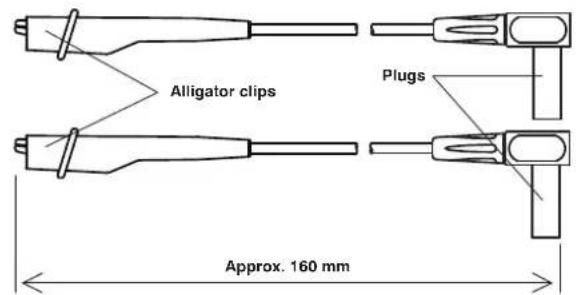
Clipping leads CL-700a (Bundled item)
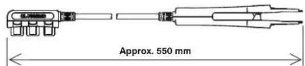
SMD Clipping leads CL-700SMD (Separately available accessory)
Shorting plate (Bundled item)
![Sanwa LCR700 - [3] PART IDENTIFICATION - 4](/content/2026/05/982929/images/3610b22182f38e4a158fc3623b3c80c69982a3d892b37244e6a2b6bbe94916af.jpg)
3-2 Display
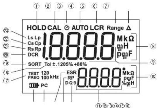
| 1 | Data hold indicator | 13 | Indicator of AC resistance in parallel mode |
| 2 | OPEN/SHORT calibration mode indicator | 14 | Equivalent series resistance mode indicator |
| 3 | Auto Power Off mode indicator | 15 | PC connection indicator |
| 4 | Series/Parallel mode automatic detection indicator | 16 | Battery capacity indicator |
| 5 | L/C/R automatic detection indicator | 17 | Measuring frequency indicator: 100 Hz, 120 Hz, 1 kHz, 10 kHz, 100 kHz |
| 6 | Range setting indicator for the sorting mode | 18 | Tolerance indicator in sorting mode: ±0.25 %, ±0.5 %, ±1 %, ±2 %, ±5 %, ±10 %, ±20 %, -20 ~ +80 % |
| 7 | Relative mode indicator | 19 | Sorting mode indicator |
| 8 | Unit of readings for main display | 20 | DC resistance mode indicator |
| 9 | Main display | 21 | Indicator of AC resistance in series or parallel mode |
| 10 | Unit of readings for sub display | 22 | Indicator of capacitance in series or parallel mode |
| 11 | Sub display | 23 | Indicator of inductance in series or parallel mode |
| 12 | Indicator of Dissipation factor (D), Quality factor (Q) or Phase angle (θ) for L/C measurement mode | ||
[4] DESCRIPTION OF FUNCTIONS
4-1 Power Switch
Press the POWER button to turn on the meter. All segments of the LCD display will be turned on for 2 seconds after power-on, and then the meter will be ready to use in the Auto LCR mode (described later). Press the POWER button again to turn off the meter. [OFF] will be indicated for 2 seconds when terning off.
4-2 Auto Power Off
When the meter is powered by the battery, Auto Power Off feature is active and is shown on the display. The buzzer beeps three times (approx. for 15 sec.) to remind the user after approx. 5 minutes of no activity. If no activity is made before beeping finishes, the meter will show [OFF] and automatically turn its power off.
To turn on the meter, press the POWER button again.
Note:
When the meter is powered through an AC/DC adopter, the Auto Power Off feature is inactive.
4-3 Buzzer
Whenever an available button is pressed in the function, the buzzer beeps one time to indicate the meter has accepted the command.
Pressing an unavailable button makes the buzzer beep 2 times.
The buzzer cannot be disabled.
4-4 Low Battery Indication
The battery condition is continuously indicated. 📄 means that the battery capacity is full. 🐎 means that battery power is low and the battery needs to be replaced. Replace the battery with new one. If you use the instrument under "Low battery", it will beep twice and show [bAtt], then turn power off.
4-5 Measuring Mode Selection
4-5-1 Auto LCR Mode
After power-on, the meter is in the Auto LCR mode as a default setting, and shows [AUTO LCR] on the display. The meter automatically selects a function, parameter, and series/parallel mode. The function and the sub parameter on the sub display will be selected based on the following conditions.
Conditions for automatic selection of functions and sub parameters.
| Functions Sub parameters Example | |||
| -11.3° ≤ ≤ 11.3° | Resistance θ | Fig. 4-5-1-1 | |
| > 11.3^ Inductance Q Fig. 4-5-1-2 | |||
| < -11.3^ Capacitance D Fig. 4-5-1-3 | |||
If C < 5 pF, Rp is shown on the sub display.
Selection of series/parallel mode depends on the total equivalent impedance measured. (Refer to 4-7)
Note:
S/P button and D/Q/θ button are not available in the Auto LCR mode.
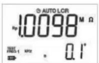
Fig. 4-5-1-1
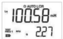
Fig. 4-5-1-2
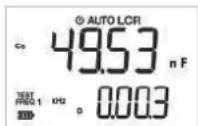
Fig. 4-5-1-3
4-5-2 Manual LCR Mode and DC Resistance Measurement
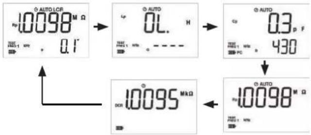
As already described, the default setting is the Auto LCR mode after power-on, the main function can be switched to the manual LCR mode or DC resistance mode by pressing the L/C/R AUTO/MANU button.
Pressing this button ( ) sequentially switches the functions as follows. Auto LCR mode Ls or Lp function Cs or Cp function Rs or Rp function DCR function Auto LCR mode
Example of resistance measurement
In the manual LCR mode, the meter automatically selects the series/parallel mode depending on the total equivalent impedance measured similarly to the Auto LCR mode. (Refer to 4-7)
The function of Ls, Lp, Cs, or Cp in the manual LCR mode shows following parameters, being switched by pressing D/Q/θ button.
| Functions Selectable parameters | |
| Ls, Cs | Dissipation factor (D), Quality factor (Q), Equivalent series resistance (ESR), and Phase angle (θ) |
| Lp, Cp | Dissipation factor (D), Quality factor (Q), Equivalent parallel resistance (Rp), and Phase angle (θ) |
Note:
- Usually quality factor (Q) is used for inductance measurement. Inductor with higher Q has lower resistance component. Usually dissipation factor (D) is used for capacitance measurement. Capacitor with lower D has lower resistance component.
Quality factor (Q)
= Inductance (L) component / Resistance (R) component Dissipation factor (D)
= Resistance (R) component / Capacitance (C) component
- ESR is used for measuring equivalent series resistance of a capacitor under a measuring frequency.
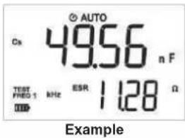
4-6 Measuring Frequency Selection
The meter provides 5 different frequencies (100 Hz/120 Hz/1 kHz/10 kHz/100 kHz)
for more accurate measurement.
The default setting is 1 kHz, and the measuring frequency can be selected by pressing the TEST FREQ button as follows.
1 kHz 10 kHz 100 kHz 100 Hz 1 kHz
Note:
The LCR impedance scale ranges and accuracies depend on the measuring frequency.
Refer to the accuracy table in Chapter 9.
4-7 Series/Parallel Mode
When measuring L/C/R with multiple element in its equivalent circuit, an appropriate measuring mode needs to be selected, assuming actual circuit to be measured.
Select the series mode if a series circuit is assumed, or select the parallel mode if a parallel circuit is assumed.
In the Auto LCR mode or manual LCR mode, the meter automatically selects the series/parallel mode depending on the total equivalent impedance measured. (The display shows [AUTO].)
10 kΩ and lower: Series mode (Ls/Cs/Rs)
Higher than 10 kΩ: Parallel mode (Lp/Cp/Rp)
In the manual LCR mode, pressing S/P button manually switches assumed series/parallel mode.
When manually selecting series/parallel mode, the display turns [AUTO] off.
4-8 Auto Range Selection
A measuring range in each function will be automatically selected, and cannot be manually selected.
4-9 Data Hold
Press HOLD button to freeze present reading for later view. (The display shows [HOLD].) Even if the DUT is disconnected from the measuring terminal, the current reading will remain on the display.
Press the HOLD button again to disable the data hold feature and go back to the normal measurement mode. (The display turns [HOLD] off.) Note:
When the reading is indefinite, the data hold feature is not available.
4-10 Relative Measurement
Relative measurement allows you to read directly the deviation in % from a reference value.
Pressing the button activates the relative mode, and the display turns [ ] on.
Note:
This function is not available in the Auto LCR mode.
Nor can it be activated when the reading is outside of the meter limits (Ex. [OL] is displayed.).
The meter uses the following formula to calculate relative measurements.
REL% = (DCUR - DREF) / DREF * 100%
REL% = Difference in percent
DCUR = Device currently under test
DREF = Device used as a reference
To enter the relative mode, proceed as follows.
- Perform the OPEN/SHORT calibration. (Refer to the section 4-11).
- Select a function from L, C, R, or DCR.
- Connect a device to the measuring terminals as a reference and wait until the readings become stable.
- Press the button to save the reading as a reference value.
Now, the display indicates [] , and the sub display shows [0.0%] .
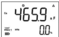
- Remove the reference device, then connect a DUT to the measuring terminals.
The main display shows the value of the DUT and the sub display shows the difference from the reference in %.
Pressing the button again shows the reference value saved in the previous step. You can check the reference value. ([ ] is blinking.)
Pressing the button again allows you to measure in the relative mode.
- Repeat Step 5 for each DUT.
Note: The range for the difference in percent is -99.9% to 99.9%. If the DUT falls outside that range, the sub display will show [OL].
- To exit this mode, press the button for 2 seconds.
4-11 OPEN/SHORT Calibration
The OPEN/SHORT calibration before measurement reduces the parasitic effect of the test fixture to get better accuracy especially for high/low impedance measurement. (For the calibration principle, see 4-15-3.)
Procedure of the OPEN/SHORT calibration
This section explanations how to perform the OPEN/SHORT calibration for a measurement using the directly connectable measuring terminals, and one for a measurement using the clipping leads "CL-700a". (Perform the OPEN/SHORT calibration according to each procedure.)
[Measurement using the directly connectable measuring terminals]
- Press the CAL button for 2 seconds. The display shows [OPEn].
![Sanwa LCR700 - [Measurement using the directly connectable measuring terminals] - 1](/content/2026/05/982929/images/52c9423b812b2294c28f3ac45e45af1aaf7bd1ce6b3422ee49191d1c0e2df128.jpg)
![Sanwa LCR700 - [Measurement using the directly connectable measuring terminals] - 2](/content/2026/05/982929/images/083d7434e2639796e6b55dd4b5825bac566bcb9418d89796b851de94bb9bd347.jpg)
natural_image
Line drawing of a handheld electronic device with control buttons and display screen (no text or symbols)- Press the CAL button again.
The meter shows a countdown on the display while it performs the OPEN calibration. It takes 30 seconds to complete.
![Sanwa LCR700 - [Measurement using the directly connectable measuring terminals] - 3](/content/2026/05/982929/images/952971ad275810ffa140bdbb5c89a41de398f3bbc518d85358274763dccb2e1e.jpg)
After the countdown is complete, the display should show [PASS].
![Sanwa LCR700 - [Measurement using the directly connectable measuring terminals] - 4](/content/2026/05/982929/images/8b1b040f62ddac1da2ef5825b8f0e395bfa147a803cbe074cc610b9e88950d66.jpg)
- Insert the bundled shorting plate to the directly connectable measuring terminals.
- Press the CAL button again. The display shows [Srt].
- Press the CAL button again. The meter shows a countdown on the display while it performs the SHORT calibration. It takes 30 seconds to complete.
![Sanwa LCR700 - [Measurement using the directly connectable measuring terminals] - 5](/content/2026/05/982929/images/c7ca2ccb3dcad2a6466c088ace5a08786d60417356f9b8f3f49dad235e636c5b.jpg)
After the countdown is complete, the display should show [PASS].
![Sanwa LCR700 - [Measurement using the directly connectable measuring terminals] - 6](/content/2026/05/982929/images/7803c14bbde7fe4463ace897c21c7082b8f23c7a8aae484f69616e5219911548.jpg)
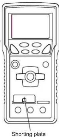
If the display shows [FAIL], this procedure has to be performed again.
![Sanwa LCR700 - [Measurement using the directly connectable measuring terminals] - 8](/content/2026/05/982929/images/8fb5f41d93ff4e4f26981ee487c29edba479780516fac1c721698d940cfc3064.jpg)
- Press the CAL button once again to exit the OPEN/SHORT calibration mode.
[Measurement using the clipping leads "CL-700a"]
- Make sure the leads are completely disconnected.
- Press the CAL button for 2 seconds. The display shows [OPEN].
![Sanwa LCR700 - [Measurement using the clipping leads "CL-700a"] - 1](/content/2026/05/982929/images/03ca40a800f5c52d2cfc20af5871e9d41186082123c2e5e3fde4cf5541247707.jpg)
- Press the CAL button again.
The meter shows a countdown on the display while it performs the OPEN calibration. It takes 30 seconds to complete.
![Sanwa LCR700 - [Measurement using the clipping leads "CL-700a"] - 2](/content/2026/05/982929/images/48c8d3ec26fe28e7cf893ea475375023e5cd457cc7f5d96cb301d50012c307c5.jpg)
After the countdown is complete, the display should show [PASS].
![Sanwa LCR700 - [Measurement using the clipping leads "CL-700a"] - 3](/content/2026/05/982929/images/a5d91b2f97218373848c3e9555759236249bbb506d61bee1307f00d1014bc9f0.jpg)
![Sanwa LCR700 - [Measurement using the clipping leads "CL-700a"] - 4](/content/2026/05/982929/images/4385828f89c47f9e7b65cff60aeb4cd42dca24f6103cbaf4fefb13f9ae04878b.jpg)
natural_image
Line drawing of a digital multimeter with dual probes and control panel (no text or symbols)- Connect the test leads to make a short circuit.
- Press the CAL button again. The display shows [Srt].
- Press the CAL button again. The meter shows a countdown on the display while it performs the SHORT calibration. It takes 30 seconds to complete.
![Sanwa LCR700 - [Measurement using the clipping leads "CL-700a"] - 5](/content/2026/05/982929/images/796ba6f41a6b45a9df7bad09d7ed227056c15633d684f26aac7e4fe173aa42f0.jpg)
After the countdown is complete, the display should show [PASS].
![Sanwa LCR700 - [Measurement using the clipping leads "CL-700a"] - 6](/content/2026/05/982929/images/80dcbf904eea3a27eab63f504a36bfcc54fae39dd55986ab77dca51978ba5884.jpg)
If the display shows [FAIL], this procedure has to be performed again.
![Sanwa LCR700 - [Measurement using the clipping leads "CL-700a"] - 7](/content/2026/05/982929/images/9d0a29f0c373e9189b6efa68e34643a164cb5e10ea6557ec230459814eaa06aa.jpg)
![Sanwa LCR700 - [Measurement using the clipping leads "CL-700a"] - 8](/content/2026/05/982929/images/d254c2ccb8a1a3c9fd112b06b3491f71aa8388386fc7ae686ce59e211326559a.jpg)
natural_image
Line drawing of a digital multimeter with two probes connected to its base (no text or symbols)- Press the CAL button once again to exit the OPEN/SHORT calibration mode.
For measurement using the SMD clipping leads "CL-700SMD" (separately available accessory), the same procedure as above can be taken to perform the OPEN/SHORT calibration.
4-12 Device Sorting
The meter can sort device values into PASS/FAIL based on resistance, capacitance, or inductance. This feature is useful in situations such as incoming inspections for mass production parts.
Note:
This function is not available in the Auto LCR mode.
Use this function in the manual LCR mode.
For details, refer to the section 5-5.
4-13 Backlight
To turn the Backlight on, press ✿ button.
To turn it off, press ✿ button again.
The Backlight is disabled automatically after the meter is inactive for 60 seconds.
4-14 PC (Personal Computer) Interface
The instrument equips with an IR interface port at the meter back for data communication. LCR-USB, dedicated USB communication unit for LCR (separately available accessory), and the dedicated software allow you to transfer real time readings to your PC and save them.
The connecting procedure is as follows.
- Snap on LCR-USB and connect the USB plug to your PC on which the dedicated software is running.
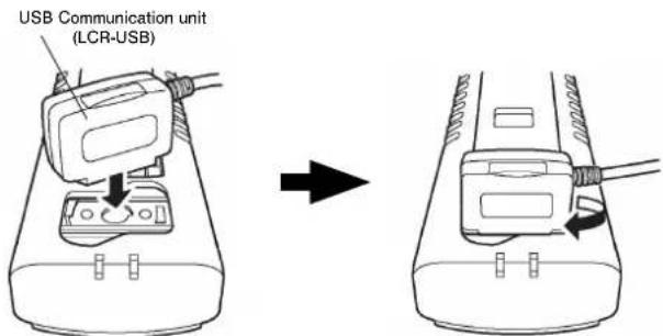
USB Communication unit connection
The display shows the readings.
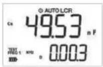
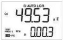
- Press the PC button.
The display shows [PC] to indicate PC connection is active.
- To make the PC connection inactive, press PC button again.
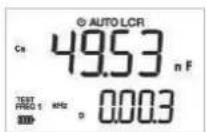
The display turns [PC] off to indicate the PC connection is inactive.
4-15 MEASURING PRINCIPLES
4-15-1 What is impedance?
Impedance Z extends the concept of resistance to AC, which is mathematically handled as a vector quantity on a complex plane. As shown, the impedance vector consists of the real part (the resistance R) and the imaginary part (the reactance X). Series impedance Zs can be represented as Rs + jXs in Cartesian form, and also can be represented as |Zs| (magnitude and phase angle) in the polar form. The figure shows a mathematical relationship between Rs, Xs, |Zs| , .
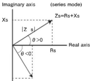
$$ Z s = R s + j X s \text { or } | Z s | \angle \theta $$
$$ R s = | Z s | \cos \theta $$
$$ X s = | Z s | \sin \theta $$
$$ X s / R s = \tan \theta $$
$$ \theta = \tan^ {- 1} (X s / R s) $$
There are two types of reactance. One is inductive reactance X_L , and the other is capacitive reactance X_C .
If > 0 , the reactance is inductive. If < 0 , the reactance is capacitive.
The inductive reactance (XL) and the capacitive reactance (XC) can be defined as follows.
$$ X _ {1} = 2 \pi f L $$
$$ X _ {c} = 1 / (2 \pi f C) $$
where:
L = Inductance
C = Capacitance
f = signal frequency
4-15-2 Impedance measurement
Impedance can be measured in series or in parallel. In parallel mode, impedance can be represented as reciprocal of admittance (Y).
The admittance can be defined as Y = G + jB .
where: G = Conductance B = Susceptance
Series impedance Parallel admittance
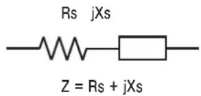

Rs = Series resistance
Xs = Series reactance
Cs = Series capacitance
Ls = Series inductance
Rp = Parallel resistance
Xp = Parallel reactance
Cp = Parallel capacitance
Lp = Parallel inductance
| Series Parallel Dissipation factor | |||
| Capacitance | Cs=Cp(1+D^2) Cp= | Cs/(1+D^2) | D=Rs/Xs= CsRs D=G/B=G/( Cp)=1/( CpRp) |
| Inductance | Ls=Lp/(1+D^2) Lp= | Ls(1+D^2) | D=Rs/Xs=Rs/( Ls) D=G/B= LpG= Lp/Rp |
| Resistance | Rs=RpD^2/(1+D^2) Rp= | Rs(1+1/D^2) — | |
| Q = Xs/Rs = 2πf Ls/Rs = 1⁄2πf CsRsQ = B/G = Rp/ | Xp| = Rp/2πf Lp = 2πf CpRp | |||
To understand the ratio of resistance and reactance, it is important to consider Quality factor (Q) and Dissipation factor (D). Usually, Q is used when measuring inductance and D is used when measuring capacitance. Q is defined as the reciprocal of D.
$$ Q = 1 / D = \tan \theta $$
Both Rs and Rp are part of the equivalent circuit of capacitors and inductors.
To measure capacitance and inductance, refer to the settings as shown in the table below.
| Value Setting | |
| Capacitance | Low Parallel |
| High Series | |
| Inductance | Low Series |
| High Parallel |
For details, refer to the section 4-7.
4-15-3 Principle of OPEN/SHORT calibration
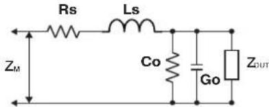
Z_M is defined as total impedance measured to a DUT by a test fixture which has some parasitic impedance.
Z_M = (Rs + j Ls) + ((Go + j Co)^-1 // Z_DUT)
Z_DUT is impedance of the DUT.
The OPEN/SHORT calibration reduces the effect of (Rs + jωLs) and (Go + jωCo).
[5] MEASURING PROCEDURE
5-1 Connection of DUT (Device Under Test)
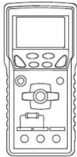
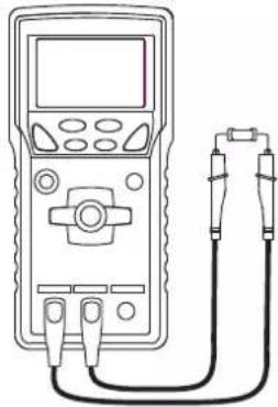
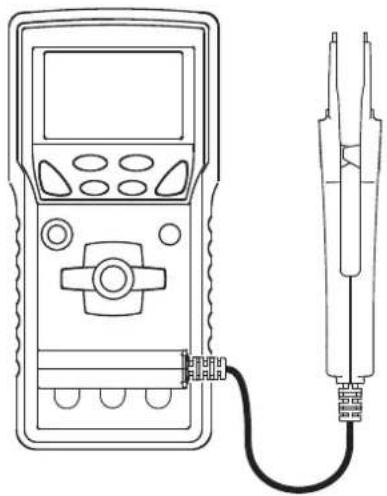
DUT's (Devices Under Test) may be connected to the meter as follows.
- Directly insert axial or radial component leads to the directly connectable measuring terminals.
natural_image
Line drawing of a handheld electronic device with control panel and display (no text or symbols)- Attach the clipping leads "CL-700a" (bundled item).
natural_image
Line drawing of a digital multimeter connected to two cables (no text or symbols)- Attach the SMD clipping leads "CL-700SMD" (separately available accessory).
natural_image
Line drawing of a digital multimeter connected to a wire with a separate test probe (no text or symbols present)CL-700SMD Electrical Characteristics
| Parameter Test Condition | 100/120 Hz | 1 kHz 10 kHz 100 kHz | |||
| Resistance: Rs Clip opened < 0.05 | Ω < 0.10 | Ω | < 0.10 Ω | < 0.10 Ω | |
| Capacitance: Cp Clip closed < 5.0 | pF < 5.0 | pF < 5.0 pF | < 5.0 pF | ||
| Inductance: Ls | Clip closed | < 1.0 μH | < 1.0 μH | < 0.5 μH | < 0.5 μH |
• Temperature: 23 °C ±5 °C, Humidity: ≤ 80 % R.H.
The guard line provides a shield for DUT, preventing interference when measuring high-impedance devices.
5-2 Pre-operational Check
WARNING
- Do not use the instrument if the meter or the clipping leads look damaged.
- Make sure the clipping leads are not broken.
CAUTION
- Make sure the battery condition is good after power-on. Replace the battery with new one if the battery power is low.
- The directly connectable measuring terminals accept axial or radial component leads up to 1.0 mm in diameter. Inserting thicker leads may damage the measuring terminals.
Perform the OPEN/SHORT calibration before measurement to ensure the safety and the accuracy.
For details, refer to the section 4-11.
5-3 Auto LCR Mode Measurement
WARNING
- Do not apply any voltage or current to the measuring terminals.
- Measuring live circuit may damage the meter.
- Do not touch any metal part of the clipping leads nor the leads of the DUT while measuring.
CAUTION
- Discharge the capacitor before any measurement.
1) Measuring ranges
L: 20.000 μH \~ 2000 H (auto-range)
C: 200.00 pF \~ 20.00 mF (auto-range)
R: 20.000 Ω \~ 200.0 MΩ (auto-range)
2) Measuring procedure
① Press the POWER button to turn the meter on.
② Press the TEST FREQ button to select a measuring frequency.
③ Connect a DUT to the measuring terminals.
④ Read the display.
Note: D/Q/θ/ESR/Rp button is not available.
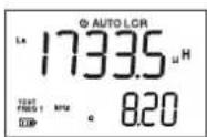
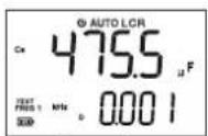
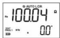
Examples
5-4 Manual LCR Mode measurement
WARNING
- Do not apply any voltage or current to the measuring terminals.
- Measuring live circuit may damage the meter.
- Do not touch any metal part of the clipping leads nor the leads of the DUT while measuring.
CAUTION
• Discharge the capacitor before any measurement.
The meter will be in Auto LCR mode after power-on.
Pressing the L/C/R AUTO/MANU button switches to Manual LCR mode and this button allows you to select the L/C/R as follows.
Auto LCR mode Ls or Lp Cs or Cp Rs or Rp DCR Auto LCR mode
(Above each function except Auto LCR mode is in Manual mode.)
5-4-1 Inductance (L) measurement
1) Measuring ranges
L: 20.000 μH \~ 2000 H (auto-range)
2) Measuring procedure
① Press the L/C/R AUTO/MANU button to select Ls or Lp function.
② Press the TEST FREQ button to select a measuring frequency.
③ Press the S/P button to select Ls or Lp.
④ Connect a DUT to the measuring terminals.
⑤ Press the D/Q/θ/ESR/Rp button to select a sub parameter. The sub parameter in the Ls function includes Q, ESR, θ, and D. The sub parameter in the Lp function includes Q, Rp, θ, and D.
⑥ Read the display.
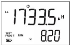
5-4-2 Capacitance (C) measurement
1) Measuring ranges
C: 200.00 pF \~ 20.00 mF (auto-range)
2) Measuring procedure
① Press the L/C/R AUTO/MANU button to select Cs or Cp function.
② Press the TEST FREQ button to select a measuring frequency.
③ Press the S/P button to select Cs or Cp.
④ Connect a DUT to the measuring terminals.
⑤ Press the D/Q/θ/ESR/Rp button to select a sub parameter. The sub parameter in the Cs function includes D, Q, ESR, and θ. The sub parameter in the Cp function includes D, Q, Rp, and θ.
⑥ Read the display.
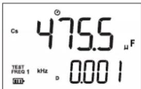
ExampleExample
5-4-3 Resistance (R) measurement
1) Measuring ranges
R: 20.000 Ω \~ 200.0 MΩ (auto-range)
2) Measuring procedure
① Press the L/C/R AUTO/MANU button to select Rs or Rp function.
② Press the TEST FREQ button to select a measuring frequency.
③ Press the S/P button to select Rs or Rp.
Any sub parameter will not be shown.
④ Connect a DUT to the measuring terminals.
⑤ Read the display.
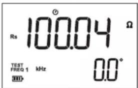
Example
5-4-4 DC Resistance measurement
1) Measuring ranges
R: 200.00 Ω \~ 200.0 MΩ (auto-range)
2) Measuring procedure
① Press the L/C/R AUTO/MANU button to select DCR function.
② Connect a DUT to the measuring terminals.
③ Read the display.
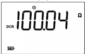
Example
5-5 Device Value Sorting
1) Measuring ranges
L: 20.000 μH \~ 2000 H (auto-range)
C: 200.00 pF \~ 20.00 mF (auto-range)
R: 20.000 Ω \~ 200.0 MΩ (auto-range)
2) Setting and Measuring procedure
① Perform the OPEN/SHORT calibration.
For details, refer to the section of "OPEN/SHORT calibration". (The OPEN/SHORT calibration is recommended for more accurate measurement.)
② Press L/C/R AUTO/MANU button to select an appropriate manual measurement function.
This button allows you to select it as follows.
Auto LCR mode Ls or Lp Cs or Cp Rs or Rp DCR Auto LCR mode
Note:
- The sorting mode is not available in the Auto LCR mode.
- S/P button allows you to select the series mode (Ls/Cs/Rs) or the parallel mode (Lp/Cp/Rp).
③ Connect a device to the measuring terminals as a reference. After the reading has stabilized, press the SORT button to launch the sorting mode, and the reading will be saved as a reference. [PASS] will be indicated as shown below.
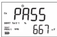
Note:
If you press the SORT button while the meter is reading outside limits (OL) or while the reading is less than 200 counts, the sorting mode is not available.
④ To set the decimal point, range, or tolerance against the reference value, press the SETUP button. The saved reference value will be shown on the display.
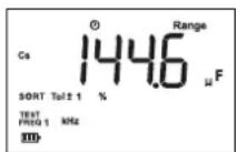
The following shows how to set up the details of the sorting mode. a. Use < and/or > keys to adjust the position of the decimal point as necessary. Press the ENTER button when finished.
b. Use <, , and/or > keys to adjust each digit as necessary. Press the ENTER button when finished.
c. Use < and/or > keys to adjust the tolerance as necessary. The tolerance options will be indicated sequentially as follows. ±0.25 %, ±0.5 %, ±1 %, ±2 %, ±5 %, ±10 %, ±20 %, -20 % \~ +80 %
Press the ENTER button when finished.
Now, the devices can be sorted.
⑤ The main display will show either [PASS] or [FAIL] as each device is measured. The sub display will show the value of the measured component, as shown in the examples below.
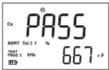
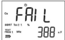
Examples
- L/C/R AUTO/MANU button, D/Q/θ/ESR/Rp button, △button, S/P button, and HOLD button will be unavailable while the instrument is in the sorting mode.
⑥ To exit the sorting mode, press the SORT button.
LCR-USB, dedicated USB optical communication unit for LCR (separately available accessory), and the dedicated software allow you to record the test results in your PC.
[6] MAINTENANCE
WARNING
- The followings are important to safety. Read this manual throughly to maintain the instrument.
- Calibrate and inspect the instrument at least once a year to ensure safety and maintain its accuracy.
6-1 Simple Examination
1) Appearance
- Check for damaged appearance by dropping down and so on.
2) Measuring terminals/Clipping leads
- Check for loose contacts between the measuring sockets and the DUT, or between the measuring terminals and the plugs.
- Check for damaged clipping lead wires.
- Check for exposed core wire anywhere on the clipping leads.
If you find any problem on the above items, stop using immediately and ask us to repair it.
Check for the clipping leads without breaking wires, referring to the section 4-11.
6-2 Battery Replacement
WARNING
Make sure the meter power is OFF, before starting the replacement.
Pre-installed battery
Since the pre-installed battery is for monitoring, it may not be durable as typically expected.
*The purpose of the battery for monitoring is to check for the functions and performances of the product.
Replacement procedure
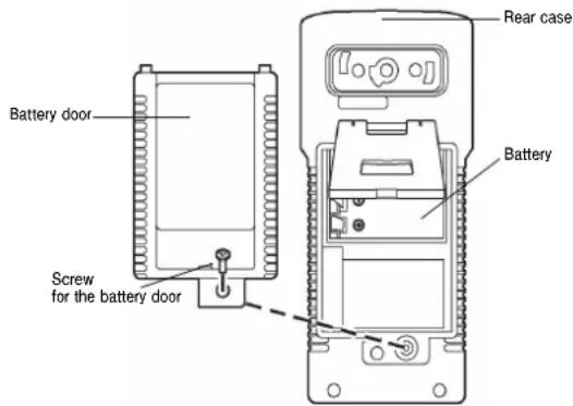
① Remove the holster and loosen the Philips-head screw fixing the battery door using appropriate screw driver.
② Remove the battery door and replace the battery with new one.
Caution: Observe correct polarity.
③ Re-fasten the screw and set the holster again.
6-3 Storage
CAUTION
- The panel and case are not resistant to volatile solvents. Do not wipe out with solvents or isopropyl alcohol. Clean the instrument up with a dry soft cloth.
- The panel and case are not resistant to heat. Keep it away from heat-generating devices such as solder irons.
- Do not save the instrument into vibratory places or where the instrument may fall off.
- Do not expose the instrument to direct sunlight and do not save it into any places with extreme temperature, humid, or condensation.
- Remove the battery for saving the instrument over a long period of time.
Save the instrument into an appropriate place, according to the precautions above. (Refer to the section 8-1.)
[7] AFTER-SALE SERVICE
7-1 Warranty and Provision
SANWA offers comprehensive warranty services to its end-users and to its product resellers. Under SANWA's general warranty policy, each instrument is warranted to be free from defects in workmanship or material under normal use for the period of one (1) year from the date of purchase.
This warranty policy is valid within the country of purchase only, and applied only to the product purchased from SANWA authorized agent or distributor.
SANWA reserves the right to inspect all warranty claims to determine the extent to which the warranty policy shall apply. This warranty shall not apply to disposables batteries, or any product or parts, which have been subject to one of the following causes:
- A failure due to improper handling or use that deviates from the instruction manual.
- A failure due to inadequate repair or modification by people other than SANWA service personnel.
- A failure due to causes not attributable to this product such as fire, flood and other natural disaster.
- Non-operation due to a discharged battery.
- A failure or damage due to transportation, relocation or dropping after the purchase.
7-2 Repair
Customers are asked to provide the following information when requesting services:
- Customer name, address, and contact information
- Description of problem
- Description of product configuration
- Model Number
- Product Serial Number
- Proof of Date-of-Purchase
- Where you purchased the product
Please contact SANWA authorized agent / distributor / service provider, listed in our website, in your country with above
information. An instrument sent to SANWA / agent / distributor without above information will be returned to the customer.
Note:
1) Prior to requesting repair, please check the following: Capacity of the built-in battery, polarity of installation and discontinuity of the test leads.
2) Repair during the warranty period:
The failed meter will be repaired in accordance with the conditions stipulated in 8-1 Warranty and Provision.
3) Repair after the warranty period has expired:
In some cases, repair and transportation cost may become higher than the price of the product. Please contact SANWA authorized agent / service provider in advance.
The minimum retention period of service functional parts is 6 years after the discontinuation of manufacture. This retention period is the repair warranty period. Please note, however, if such functional parts become unavailable for reasons of discontinuation of manufacture, etc., the retention period may become shorter accordingly.
4) Precautions when sending the product to be repaired: To ensure the safety of the product during transportation, place the product in a box that is larger than the product 5 times or more in volume and fill cushion materials fully and then clearly mark "Repair Product Enclosed" on the box surface. The cost of sending and returning the product shall be borne by the customer.
7-3 SANWA web site
http://www.sanwa-meter.co.jp
E-mail: exp_sales@sanwa-meter.co.jp
[8] SPECIFICATIONS
8-1 General Specifications
| LCD display(with Backlight) | Main display | 20,000 counts: Ls/Lp/Cs/Cp/Rs/Rp/DCR |
| Sub display | 2,000 counts: D/Q/θ/ESR/RP | |
| Over-range indication | While the meter is reading outside limits, numeric part of the display indicates [OL]. | |
| Battery power indication | 4 levels | |
| Measurable parameters | Ls / Lp / Cs / Cp / Rs / Rp / DCR(including D/Q/θ/ESR/RP) | |
| Measuring mode | Series / Parallel | |
| Range selection | Automatic | |
| Measuring terminals | 4 terminals plus guard shieldingAccepts the plugs of the clipping leads. | |
| Auto LCR measurement ranges | L: 20.000 μH ~ 20.000 kHC: 200.00 pF ~ 20.00 mFR: 20.000 Ω ~ 200.0 MΩ | |
| DCR measurement ranges | R: 200.00 Ω ~ 200.0 MΩ | |
| Measuring frequencies | 100 Hz / 120 Hz / 1 kHz / 10 kHz / 100 kHz | |
| Measurement rate | 1.2 times / second (LCR mode)0.5 times / second (DCR mode) | |
| Selectable tolerances | ±0.25 %, ±0.5 %, ±1 %, ±2 %, ±5 %, ±10 %, ±20 %,-20 % ~ +80 % | |
| Measuring signal level | 0.63 Vrms (nominal), 0.9 Vdc (nominal) | |
| Operating conditions | Altitude: < 2,000 m Pollution degree: II | |
| Specification guaranteed temperature/humidity | 18 ~ 28 °C < 80 % RH | |
| Temperature coefficient | [0.15 x (specified accuracy)]/°C0 ~ 18 °C, 28 ~ 50 °C | |
| Operating temperature/humidity | 0 ~ 50°C < 80 % RH | |
| Storage temperature/humidity | -20 ~ 60 °C < 80 % RH | |
| EMC directive,RoHS directive | IEC61326-1(EMC), EN50581(RoHS)Under a condition field strength CS 3 V (0.15-80 MHz):The following shows a total accuracy of the DC resistance measurement.Total accuracy = specified accuracy ± 150 dgtIn other ranges or a condition which is worse than the above-described condition, the accuracy is not specified. | |
| Power source | Single alkaline 9 V battery 6LR61(IEC6LF22,NEDA1604A) or an external AC/DC adopter(separately available: AD-30-2) | |
| Auto Power Off | 5 minutes after the last operation | |
| Power consumption | Approx. 110 mW | |
| Battery life | Approx. 35 hours (Auto LCR Mode, 1 kHz) | |
| Dimensions | without holster | Approx. L 175 mm × W 80 mm × H 40 mm |
| with holster | Approx. L 184 mm × W 87 mm × H 45 mm | |
| Mass | without holster | Approx. 320 g |
| with holster | Approx. 400 g | |
| Accessories | Clipping leads (CL-700a),Holster (H-701)Shorting plate for the directly connectable measuring terminals Instruction manual | |
| Separately available accessories | AC/DC adopter (AD-30-2),SMD clipping leads (CL-700SMD)LCR USB communication unit (LCR-USB)(PC communication software bundled) | |
8-2 Measuring Range and Accuracy
Accuracy: ±(% rdg + dgt) " % + d " is an abbreviation.
rdg: reading
dgt: least significant digit
Temperature: 23 °C ±5 °C
Humidity: ≤ 80 % R.H.
(≤ 60 % R.H. for the range of 2 MΩ, 20 MΩ, and 200 MΩ)
The accuracy when using the dedicated accessory CL-700a or
CL-700SMD after OPEN / SHORT calibration is shown below.
" - ": the accuracy is not guaranteed.
Resistance: Rp, Rs
| Range | Resolution | DCR | 100/120 Hz | 1 kHz | 10 kHz | 100 kHz | ||
| 20 Ω | 0.01 Ω | - | 0.7% + 8 d | -- | ||||
| 0.001 Ω | - | 0.7% + 8 d | 0.7% + 8 d | 0.7% + 8 d | ||||
| 200 Ω | 0.01 Ω | 0.3% | + 3 d | 0.3% + 3 d | 0.3% + 3 d | 0.3% + 3 d | 0.5% + 5 d | |
| 2 kΩ | 0.001 kΩ | 0.3% | + 3 d | 0.3% + 3 d | 0.3% + 3 d | 0.3% + 3 d | 0.5% + 5 d | |
| 20 kΩ | 0.001 kΩ | 0.3% | + 3 d | 0.3% + 3 d | 0.3% + 3 d | 0.3% + 3 d | 0.7% + 8 d | |
| 200 kΩ | 0.01 kΩ | 0.5% | + 5 d | 0.3% + 3 d | 0.3% + 3 d | 0.3% + 3 d | 0.9% + 10 d | |
| 2 MΩ | 0.0001 MΩ | 0.5% + 5 d | 0.5% + 5 d | 0.5% + 5 d | 2.0% + 10 d | - | ||
| 20 MΩ | 0.001 MΩ | 2.0% + 8 d | 2.0% + 10 d | 3.0% + 20 d | - | - | ||
| 0.01 MΩ | - | - | - | 5.0% + 80 d | - | |||
| 200 MΩ | 0.1 MΩ | 5.0% + 80 d | 5.0% + 80 d | - | - | - | ||
Capacitance: Cp, Cs (When D < 0.1)
| Range | Resolution | 100/120 Hz | 1 kHz | 10 kHz | 100 kHz |
| *200 pF | 0.01 pF | - | - | 0.8 % + 10 d | 2.0 % + 10 d |
| 2000 pF | 1 pF | 0.5 % + 5 d | - | - | - |
| 0.1 pF | - | 0.5 % + 5 d | 0.5 % + 5 d | 1.5 % + 10 d | |
| 20 nF | 0.001 nF | 0.5 % + 5 d | 0.3 % + 3 d | 0.5 % + 5 d | 0.7 % + 10 d |
| 200 nF | 0.01 nF | 0.3 % + 3 d | 0.5 % + 5 d | 0.5 % + 5 d | 0.7 % + 10 d |
| 2000 nF | 0.1 nF | 0.3 % + 3 d | 0.3 % + 3 d | 0.5 % + 5 d | 3.5 % + 10 d |
| 20 μF | 0.001 μF | 0.3 % + 3 d | 0.3 % + 3 d | 1.0 % + 10 d | - |
| 200 μF | 0.01 μF | 0.3 % + 3 d | 0.8 % + 10 d | - | - |
| 0.1 μF | - | - | 3.5 % + 10 d | - | |
| 2000 μF | 0.1 μF | 2.0 % + 10 d | - | - | - |
| 1 μF | - | 1.5 % + 10 d | - | - | |
| 20 mF | 0.01 mF | 1.5 % + 10 d | - | - | - |
* Accuracy is not guaranteed under 50 pF.
- Accuracy when D ≥ 0.1: A e × 1 + D^2
Ae means an accuracy of rdg in the main display.
Inductance: Lp, Ls (When D < 0.1)
| Range Resolution | 100/120 Hz 1 kHz 10 kHz 100 kHz | |||||||
| 20 μH | 0.001 μH | - | - | 1.0 % + 10 d | ||||
| 200 μH | 0.01 μH | - | 0.8 % + 10 d | 1.0 % + 10 d | ||||
| 2000 μH | 0.1 μH | - | 0.8 % + 10 d | 0.5 % + 5 d | 0.8 % + 10 d | |||
| 20 mH | 0.001 mH | 0 | 8 % + 10 d | 0.3 % + 3 d | 0.5 % + 5 d | 0.8 % + 10 d | 0.8 % + 10 d | |
| 200 mH | 0.01 mH | 0 | 5 % + 5 d | 0.5 % + 5 d | 0.8 % + 10 d | - | ||
| 2000 mH | 0.1 mH | 0 | 0.3 % + 3 d | 0.5 % + 5 d | 0.8 % + 10 d | - | ||
| 20 H | 0.001 H | 0 | 0.3 % + 3 d | 0.3 % + 3 d | 5.0 % + 20 d | - | ||
| 200 H | 0.01 H | 0 | 0.5 % + 5 d | 0.8 % + 10 d | - - | |||
| 2000 H | 0.1 H | 0 | 0.8 % + 10 d | 3.0 % + 20 d | - | - | ||
| 20 kH | 0.001 kH | 5.0 % + 20 d | - - - | |||||
- Accuracy when D ≥ 0.1: A e × 1 + D^2
Ae means an accuracy of rdg in the main display.
Accuracy of e : e = ± (180 / ) × Ae (deg)
Ae means an accuracy of rdg in the main display.
Unit:
Display range: -90.0° to 90.0°
• In the capacitance measurement
| Range 100/120 Hz | 1 kHz | 10 kHz | 100 kHz | |
| 200 pF | - | - | ±0.46 | ±1.15 |
| 2000 pF ±0.29 | ±0.29 | ±0.29 | ±0.86 | |
| 20 nF | ±0.29 | ±0.17 | ±0.29 | ±0.40 |
| 200 nF | ±0.17 | ±0.29 | ±0.29 | ±0.40 |
| 2000 nF ±0.17 | ±0.17 | ±0.29 | ±2.01 | |
| 20 μF | ±0.17 | ±0.17 | ±0.57 | - |
| 200 μF | ±0.17 | ±0.46 | ±2.01 | - |
| 2000 μF | ±1.14 | ±0.86 | - | - |
| 20 mF ±0.86 | - | - | - | |
• In the inductance measurement
| Range 100/120 Hz | 1 kHz | 10 kHz | 100 kHz | |
| 20 μH | - | - | - | ±0.57 |
| 200 μH | - | - | ±0.46 | ±0.57 |
| 2000 μH | - | ±0.46 | ±0.29 | ±0.46 |
| 20 mH | ±0.46 | ±0.17 | ±0.29 | ±0.46 |
| 200 mH | ±0.29 | ±0.29 | ±0.46 | - |
| 2000 mH ±0.17 | ±0.29 | ±0.46 | - | |
| 20 H | ±0.17 | ±0.17 | ±2.87 | - |
| 200 H | ±0.29 | ±0.46 | - | - |
| 2000 H | ±0.46 | ±1.72 | - | - |
| 20 kH | ±2.87 | - | - | - |
Accuracy of D value De: De = ±Ae
Display range: 0.000 to 1999
Ae means an accuracy of rdg in the main display.
Ex. Capacitor to be measured: 180 nF
Test frequency: 1 kHz
Measuring accuracy: ±(0.3 %rdg + 3 dgt)
Ae = 0.3 %rdg
Calculation for De (Accuracy of D value):
De= ±0.003
Accuracy of ESR: Re = ± Z_M× Ae()
Display range: 00.00 to 199.9 MΩ
Calculation for Z_M : 1/(2πfC) or 2πfL
Ex. Capacitor to be measured: 180 nF
Test frequency: 1 kHz
Measuring accuracy: ±(0.3 %rdg + 3 dgt)
Ae = 0.3 %rdg
Z_M = 1 / (2 × 3.14 × 1000 × 180 × 10^-9)
= 884.6 Ω
Re = ± 0.003× 884.6
= ± 2.65 Ω
Accuracy of Q value Qe : Q_e = ± ^2 · D_e1 - Q · D_e
Display range: 0.000 to 1999
Condition: Q · De < 1
Ex. Inductor to be measured: 180 μH
Test frequency: 10 kHz
Measuring accuracy: ±(0.5 %rdg + 3 dgt)
Assumption: De = Ae = ±0.005
Measured Q value: 20
Qe = ±20 × 20 × 0.005 / (1 - 20 × 0.005)
= 2.22
4-terminal measurement with guard shielding:
The DUT measuring leads are implemented by 4-terminal measurement. It is necessary to perform the OPEN/SHORT calibration to obtain the accuracy shown above.
The product specifications and its appearance described in this manual are subject to change without prior notice for improvements or other reasons.
< MEMO >
sanwa®
三和電気計器株式会社
- [1] SAFETY PRECAUTIONS
- [2] APPLICATIONS AND FEATURES
- [3] PART IDENTIFICATION
- [4] DESCRIPTION OF FUNCTIONS
- [5] MEASURING PROCEDURE
- [6] MAINTENANCE
- [7] AFTER-SALE SERVICE
- 1-1 Explanation of Warning Symbols
- 1-2 Warning Instructions for Safe Use
- WARNING
- CAUTION
- [2]APPLICATIONSANDFEATURES
- 2-1 Applications
- 2-2 Features
- 4-1 Power Switch
- 4-2 Auto Power Off
- 4-3 Buzzer
- 4-4 Low Battery Indication
- 4-5 Measuring Mode Selection
- 4-5-1 Auto LCR Mode
- 4-5-2 Manual LCR Mode and DC Resistance Measurement
- Note:
- Quality factor (Q)
- 4-6 Measuring Frequency Selection
- 4-7 Series/Parallel Mode
- 4-8 Auto Range Selection
- 4-9 Data Hold
- 4-10 Relative Measurement
- 4-11 OPEN/SHORT Calibration
- Procedure of the OPEN/SHORT calibration
- [Measurement using the directly connectable measuring terminals]
- [Measurement using the clipping leads "CL-700a"]
- 4-12 Device Sorting
- 4-13 Backlight
- 4-14 PC (Personal Computer) Interface
- 4-15 MEASURING PRINCIPLES
- 4-15-1 What is impedance?
- 4-15-2 Impedance measurement
- Series impedance Parallel admittance
- 4-15-3 Principle of OPEN/SHORT calibration
- 5-1 Connection of DUT (Device Under Test)
- 5-2 Pre-operational Check
- 5-3 Auto LCR Mode Measurement
- 5-4 Manual LCR Mode measurement
- 5-4-1 Inductance (L) measurement
- 5-4-2 Capacitance (C) measurement
- 5-4-3 Resistance (R) measurement
- 5-4-4 DC Resistance measurement
- 5-5 Device Value Sorting
- Examples
- 6-1 Simple Examination
- 6-2 Battery Replacement
- Pre-installed battery
- Replacement procedure
- 6-3 Storage
- 7-1 Warranty and Provision
- 7-2 Repair
- 7-3 SANWA web site
- [8] SPECIFICATIONS
- 8-2 Measuring Range and Accuracy
- Accuracy of D value De: De = ±Ae
- Accuracy of ESR: Re = ± Z_M× Ae()
- 4-terminal measurement with guard shielding:
- sanwa®
- 三和電気計器株式会社
Brand : Sanwa
Model : LCR700
Category : Measurement