PAC15 - Air conditioner Climachill - Free user manual and instructions
Find the device manual for free PAC15 Climachill in PDF.


| Product Type | Portable Air Conditioner |
| Model | PAC15 |
| Brand | Climachill |
| Cooling Capacity | 12000 BTU (approx. 3.5 kW) |
| Power Supply | 230 V / 50 Hz |
| Power Consumption (Cooling) | 1100 W |
| Airflow Rate | 300 m³/h |
| Dehumidification Capacity | 1.5 L/h |
| Refrigerant | R-410A |
| Noise Level | 54 dB(A) |
| Dimensions (W x D x H) | 45 x 35 x 70 cm |
| Weight | 25 kg |
| Functions | Cooling, Dehumidification, Fan |
| Thermostat Control | Digital with remote control |
| Timer | 24-hour programmable |
| Filter | Washable mesh filter |
| Maintenance | Clean filter every 2 weeks; drain condensate |
| Safety Features | Overheat protection, auto restart |
| Warranty | 2 years |
| Spare Parts Availability | Contact authorized service center |
| Energy Efficiency Class | A |
Frequently Asked Questions - PAC15 Climachill
User questions about PAC15 Climachill
0 question about this device. Answer the ones you know or ask your own.
Ask a new question about this device
Download the instructions for your Air conditioner in PDF format for free! Find your manual PAC15 - Climachill and take your electronic device back in hand. On this page are published all the documents necessary for the use of your device. PAC15 by Climachill.
USER MANUAL PAC15 Climachill
Portable Air Conditioner and Heater With Heat Pump Technology
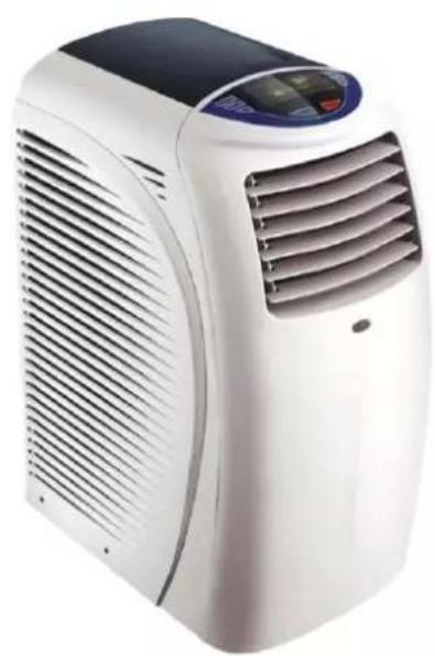
natural_image
White industrial air conditioner unit with black ventilation grille and digital display (no visible text or symbols)PAC12

natural_image
White portable air conditioner unit with ventilation grille and control panel (no visible text or symbols)PAC15
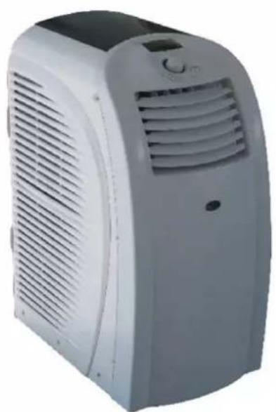
natural_image
Exterior view of a white portable air conditioner unit with ventilation slots and control panel (no visible text or symbols)PAC18
Please read this manual carefully prior to operating the product.
TABLE OF CONTENTS
INTRODUCTION....3
IMPORTANT SAFEGUARDS....4
PRODUCT DIAGRAM....5-6
INSTALLATION 7
WINDOW KIT INSTALLATION 8
CONTROL PANEL AND MULTI-COLOR DISPLAY (PAC12) 9
CONTROL PANEL AND MULTI-COLOR DISPLAY (PAC15) 10
CONTROL PANEL AND MULTI-COLOR DISPLAY (PAC18) 11
CONTROL PANEL FUNCTIONS 12
COOLING MODE 13
DEHUMIDIFYING MODE 13
FAN MODE....13
HEATINGMODE 13
AUTO MODE....13
SLEEP MODE 14
Thank you for purchasing the PAC12, PAC15 or PAC18 Portable Air Conditioner and Heater. This unit is designed to improve indoor living and working comfort by providing cooling, dehumidifying, heating, and ventilation with minimal installation.
Please complete the following information for future reference. Retain this owner's manual with your sales receipt as a permanent record of your purchase.
Serial Number: ____
Date of Purchase: ____
Place of Purchase: ____
IMPORTANT SAFEGUARDS
Before installing and using your portable air conditioner and heater, it is important that you read this owner's manual carefully. Store this manual in a safe place for future reference.
This instruction manual is used for guidance and does not form part of a contract. It reserves the right to make technical changes without prior notice.
- Always place the unit on a level surface.
- The appliance shall be installed in accordance with national wiring regulation.
- The unit must be connected to a correctly grounded power supply. For your safety, this unit is grounded through the power cord plug when connected to a grounded wall outlet. Do not use an adapter plug or extension cord.
- Do not install the unit in an area where gas leakage may occur and/or in an explosive atmosphere.
- Do not apply an insecticide or any type of flammable spray on the unit.
- Confirm drainage piping is connected properly.
- Do not start or stop the unit by inserting or pulling out the power plug.
- Do not operate with wet hands.
- Close supervision is necessary when the unit is used near children. The unit in not intended for use by children.
- Do not insert anything into the air outlet. Do not obstruct air inlet or outlet grills.
- Do not expose skin or eyes directly to cool air for a long period of time.
- If an abnormal odour or smoke comes out of the unit, disconnect the unit immediately and contact a qualified service technician.
- When opening the filter cover, do not touch the metal parts in the unit's interior.
- Do not immerse the unit in water or any type of liquid. Do not use the unit in the immediate surroundings of a bath, shower, or swimming pool, or in any other steamy, wet areas.
- When cleaning the unit, always turn the unit off and unplug the power cord.
- Always inspect the power cord for signs of damage before use. If the power cord is damaged, it must be replaced by the manufacturer or a qualified service technician.
- Do not place a plant or allow a pet in the direct path of the airflow to avoid injury.
- Do not put a stove, etc, where it would be exposed to the direct airflow. It may affect combustion.
- Do not sit on the unit or place anything on it.
- Before storing, the water must be drained from the unit and the filters cleaned.
PRODUCT DIAGRAM
FRONT (PAC12)
A. Control panel
B. Vertical air louvers
C. Air outlet
D. Castors
E. Cable (power cord and plug)

FRONT (PAC15)
A. Control panel
B. Vertical air louwers
C. Air outlet
D. Horizontal air louvers
E. Castors
F. Cable (power cord and plug)

FRONT (PAC18)
A. Control panel
B. Vertical air louvers
C. Air outlet
D. Castors
F. Cable (power cord and plug)

BACK
A. Hot air outlet grill
B. Lower air inlet grill

natural_image
Technical line drawing of a portable air conditioner unit with labeled parts A and B (no text or symbols beyond labels)ACCESSORIES
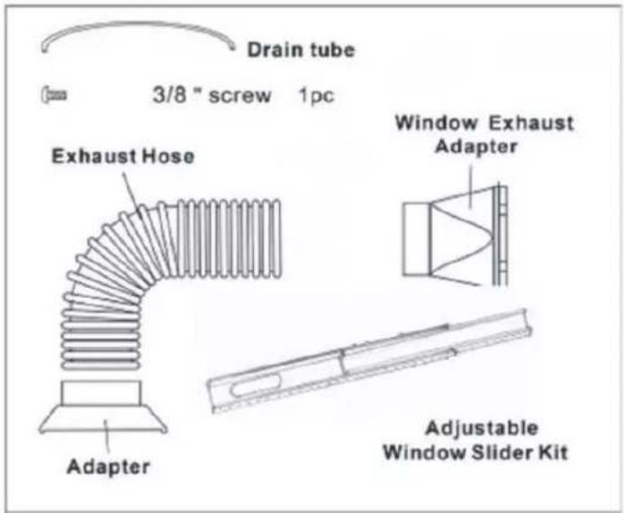
Flexible exhaust hose with 2 adapters
- 3-piece set
• stretches from 14 1/4" to 60 5/8"
(36cm to 150cm)
Window exhaust adapter
Adjustable window slider kit
- 3-piece set
- adjusts 33 1/2" to62" (85cm to 157.5cm)
Drain tube
Drain pan
INSTALLATION
SELECTING THE LOCATION
Place the unit in a flat location where the air outlets are not obstructed. Place the unit at least 20" (50cm) away from a wall or other obstacle.
MOUNTING THE EXHAUST HOSE
Slide the square end of the exhaust duct over the hot air outlet on the back of the unit.
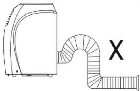
The exhaust hose should be kept as short and straight as possible. Prevent any sharp bends in the exhaust hose, as this will trap hot exhaust air.
The hot exhaust air can be vented through the wall or out a window. If mounting in the wall, the height of the hole should be 16 to 50 inches (40cm to 130cm).

natural_image
Line drawing of a portable air conditioner unit with 20-inch height annotations (no text or symbols on the device itself)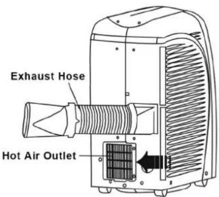

natural_image
Diagram of a portable air duct connected to a device, with a labeled X symbol (no text or labels present)WINDOW KIT INSTALLATION
The window kit is designed to fit into most standard vertical and horizontal windows. However, it may be necessary to modify some aspects of the installation process for certain window types.
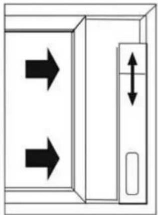
- Open the window or sliding door and adjust the length of the window kit to fit the opening. Mark and cut down a single panel of the window kit if necessary.
- Place the window kit between the window and the window frame as shown in the images to the right. Close the window onto the window kit to form a tight seal.
- Attach the exhaust duct adapter to the window kit. Tabs located on the adapter will lock into place securing the adapter to the window kit.
HORIZONTAL WINDOW

natural_image
Simple line drawing of a device with two downward arrows and an internal bidirectional arrow (no text or symbols)Window Slider Kit
Minimum: 33^1/2 (85cm)
Maximum:70"(177.8)

natural_image
Line drawing of a medical device with a monitor and connector (no text or symbols)VERTICAL WINDOW
natural_image
Diagram showing two arrows pointing up and down a vertical double-headed arrow inside a rectangular box (no text or symbols)
natural_image
Line drawing of an air conditioner unit with airflow direction arrows (no text or symbols)Window Slider Kit
Minimum: 3312 (85cm)
Maximum: 70°(177.8)
CONTROL PANEL AND MULTI-COLOR DISPLAY (PAC12)
CONTROL PANEL
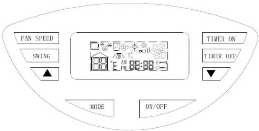
| FAN SPEED Button | Press this button to choose high, medium or low fan speed. In dehumidifying mode, this button is inoperable. |
| SWING Button Press this button to oscillate the vertical louvers or to stop oscillation. | |
| ∨ Button | This button decreases the room temperature/timer hours. |
| ∧ Button | This button increases the room temperature/timer hours. |
| Power Button Press this button to turn the unit on or off. | |
| MODE Button Press this button to select the mode (auto, cooling, dehumidifying, fan or heating). | |
| TIMER Button | Press this button to turn the timer on/off. |
A. Auto Mode
B. Cool Mode
C. Dehumidify Mode
D. Fan Mode
E. Heat Mode
F. Fan Speed (Low, High, Medium)
G. Temperature
H. Swing Mode
I. Sleep Mode
J. Clock and Timer
K. Timer On
L. Timer Off
M. Compressor is on

CONTROL PANEL AND MULTI-COLOR DISPLAY (PAC15) CONTROL PANEL

| FAN SPEED Button | Press this button to choose high, medium or low fan speed. In dehumidifying mode, this button is inoperable. |
| SWING Button Press this button to oscillate the vertical louvers or to stop oscillation. | |
| √ Button | This button decreases the room temperature/timer hours. |
| ^ Button | This button increases the room temperature/timer hours. |
| Power Button Press this button to turn the unit on or off. | |
| MODE Button Press this button to select the mode (auto, cooling, dehumidifying, fan or heating). | |
| TIMER Button Press this button to turn the timer on/off. | |
MULTI-COLOR DISPLAY
A. Auto Mode
B. Cool Mode
C. Dehumidify Mode
D. Fan Mode
E. Heat Mode
F. Fan Speed (Low, High, Medium)
G. Temperature
H. Swing Mode
I. Sleep Mode
J. Clock and Timer
K. Timer On
L. Timer Off
M. Compressor is on

CONTROL PANEL AND MULTI-COLOR DISPLAY (PAC18)
CONTROL PANEL

| Power Button Press | Press button to turn the unit on or off. |
| Mode Button Press | this button to select the mode (auto, cooling, dehumidifying, fan or heating). |
| Swing Button Press | this button to oscillate the vertical louvers or to stop oscillation. |
| Fan Speed Button | Press this button to choose high, medium or low fan speed. In dehumidifying mode, this button is inoperable. |
| Dial Button (push in) | When the unit is not working, press this button to turn the timer on. |
| Dial Button (push in) | When the unit is working, press this button to turn the timer off. |
| Dial Button (turn left) | Turning the dial left decreases the room temperature - /time hours-. |
| Dial Button (turn right) | Turning the dial right increases the room temperature + /time hours+. |
MULTI-COLOR DISPLAY
A. Auto Mode
B. Cool Mode
C. Dehumidify Mode
D. Fan Mode
E. Heat Mode(if only cooling not work)
F. Fan Speed (Low, High, Medium)
G. Compressor is on F
H. Swing Mode
I. Sleep Mode
J. Temperature and Timer
K. Time On
L. Time Off
M. Water full

CONTROL PANEL FUNCTIONS
Press to select the operating mode:
Fan Mode
Air Conditioning Mode
Heating Mode
Dehumidifying Mode
Auto Mode
FAN BUTTON
Press to select the fan speed: High, Medium, and Low.
The fan speed can be visually distinguished by the number of the digital air segments (follow arrow above) flow out from the windmill fan image on the multi-colour display.
TEMPERATURE
When in cooling or heating mode, the desired temperature can be selected by pressing the and buttons. The multi-colour display flashes the temperature while it is being set. The multi-colour display shows the set temperature when it is not in temperature setting mode.
The multi-colour display can show either Celsius or Fahrenheit. Press the ∧ and ∨ buttons simultaneously to change the display from Celsius to Fahrenheit or vice versa.
TIMER
To set the auto start time, press the Timer on button until the multi-colour display shows a flashing “”. Press the ∧ and ∨ buttons to change the clock to the desired time for the unit to automatically start. To set the
auto stop time, press the Timer Off button and the multi-colour display will show a flashing “”. Press the ∧ and ∨ buttons to change the clock to the desired time for the unit to automatically stop. The light will flash for 3 seconds to activate the timer you programmed.
TIME DISPLAY
In the diagram above, the letter "J" points to the adjustable time display. To adjust the time, Press FAN, SPEED and SWING together (at the same time), then press UP to adjust the hours, and press DOWN to adjust the minutes.
SWING
To start horizontal oscillation, press the Swing button once. ' / / or 📄' icon will appear on the multi-colour display. To stop oscillation, press the Swing button again. Vertical air flow direction can be adjusted manually.
TEMPERATURE DIAL (PAC18)
When in cooling or heating mode, the desired temperature can be selected by turn left and turn right buttons. The multi-colour display flashes the temperature while it is being set. The multi-colour display shows the set temperature when it is not in temperature setting mode.
The multi-colour display can show either Celsius or Fahrenheit. Turn left and turn right buttons simultaneously to change the display from Celsius to Fahrenheit or vice versa.
TIMER DIAL (PAC18)
When the unit is not working turn down dial to set the auto start time, until the multi-colour display shows a flashing “→”. when the unit is working turn down dial to set the auto stop time, press the Timer Off button and the multi-colour display will show a flashing “→”. Turn left and turn right buttons to change the clock to the desired time for the unit to automatically stop. The light will flash for 3 seconds to activate the timer you programmed.
- Properly install the exhaust hoses.
- Plug the power cord into a grounded outlet.
- Turn on the unit by pressing the On/Off button on the control panel.


- Press the Mode button until "or " icon appears on the multi-colour display.
- Press the or buttons until the desired temperature appears on the multi-colour display. The temperature ranges from 61^ - 88^ ( 16^ - 31^ ).
- Select the fan speed by pressing the Fan button.
NOTE: During hot days, the unit will cool off the room most efficiently by setting the temperature at the lowest and the fan speed at the highest. Reducing the length of the exhaust hoses, insulating the exhaust hoses, and keeping direct sunlight to a minimum will also improve the cooling efficiency.
DEHUMIDIFYING
- Properly install the exhaust hoses.
- Plug the power cord into a grounded outlet.
-
Turn on the unit by pressing the On/Off button on the control panel.
-
Press the Mode button until the "☐ or ☐" icon appears on the multi-colour display.
NOTE: The unit operates at low fan speed during dehumidifying. The unit cools the room slightly during dehumidification.
Keep the windows and the doors closed to aid in the effectiveness of the unit in removing the moisture from the room.
NOTE: The unit will not dehumidify when the room temperature is lower than 61°F.
FAN MODE
- Plug the power cord into a grounded outlet.
-
Turn on the unit by pressing the On/Off button on the control panel.
-
Press the Mode button until " " icon appears on the multi-colour display.
-
Select the fan speed by pressing the Fan button.
NOTE: When the unit is running on fan mode, the exhaust hoses are inoperative and are not required.
HEATING
- Plug the power cord into a grounded outlet.
-
Turn on the unit by pressing the On/Off button on the control panel.
-
Press the Mode button until “ ” icon appears on the multi-colour display.
-
Press the or button until the desired room temperature appears on the multi-colour display. The temperature ranges from 61^ F - 88^ F ( 16^ C - 31^ C).
-
Select the fan speed by pressing the Fan button. It is recommended to use the low fan speed.
NOTE: When the unit is running on heating mode, the exhaust hose is operative the same way as cooling mode.
AUTO MODE
- Properly install the exhaust hoses.
- Plug the power cord into a grounded outlet.
-
Turn on the unit by pressing the On/Off button on the control panel.
-
Press the Mode button until the “or” button appears on the multi-colour display.
-
Press the Fan button to select the fan speed.
During the Auto mode, The unit operates in dehumidifying mode when the room temperature is between 68 °F - 73°F. The unit operates in cooling mode when the room temperature is above 73 °F. You may use the timer with the Auto mode.
SLEEP MODE
(This mode can only be programmed from the remote control.)
- The air conditioner will need to be in operation.
- Press the Sleep button. The “ ” icon appears on the multi-colour display.
- The fan motor runs at low speed.
- When in cooling mode, the temperature will increase 1^ F per hour during the first two hours. Then the temperature will stay 2^ F higher than the originally set temperature for 6 hours. 6 hours later, the unit will shut down.
- When in dehumidify mode, the temperature will not change.
NOTE: If the unit is turned off during cooling, dehumidifying, or heating and then restarted, there will be a 3 minute delay before the compressor will turn back on to prolong the life of the compressor. Once the power recovers and the compressor restarts, the unit will return to the original working mode.
REMOTE CONTROL & OPERATION (PAC15/18 ONLY)
The remote control provided with the unit can be used to operate the portable air conditioner. The remote control uses 2 AAA batteries (provided). Install the batteries before using the remote control.
The remote control can be used to do all the operations that can be programmed from the control panel.
The LCD display on the remote control can show either Celsius or Fahrenheit. Press the + and - keys simultaneously to change the display from Celsius to Fahrenheit or vice versa.

WATER DRAINAGE
When the unit is in cooling mode, unwanted water is extracted from the air. Most of this water is re-used to cool the unit and make it run more efficiently. When the unit is used in extremely humid environments, water will collect in a water container at the bottom of the unit. When the water container is full, the compressor will stop but the fan will continue to run.
When the water container is full, the unit will display 'FULL or 📁' on the control panel until the tank is emptied. To resume operation, empty the water container according to the following steps:
- Turn the unit off. Do not move the unit when the water container is full.
- Place the drain pan accessory under the drainage port at the back of the unit.
- Remove the rubber plug from the drain hole. The condensate water will drain out automatically. When the drain pan is full, replace the rubber plug into the drainage hole to stop the water flow. Empty the drain pan. Repeat until all the water is emptied.
- Once the water container has been emptied, replace the rubber plug into the drain hole firmly. Do not allow the water to drip continuously into the drain pan, as it might easily overflow.


NOTE: In heating mode, the drain pipe accessory must be used to empty the water container.
- Remove the rubber plug and keep for future use.
- Connect the drain tube accessory to the drain hole. Place drain pan at end of drain tube; water will drain out automatically during operation.
HIGH HUMIDITY WATER RELEASING FEATURE (PAC18)
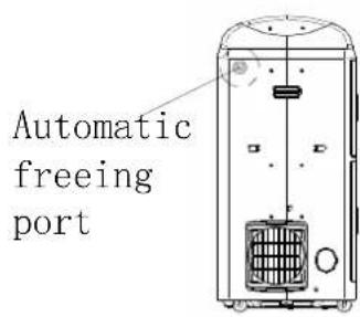
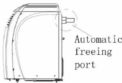
When used in high humidity areas, more water can be created than the unit can re-use, when this happens the internal tank will fill up, cooling will stop and the unit requires emptying. The PAC18 model features a water releasing function, this allows you to connect a water drain pipe to the upper water removal port and thus allows continuous use of the machine without fear of it turning itself off. When this feature is desired connect the 3m water pipe to the port then drain the water (making sure the water goes downhill!), if this feature is not required please ensure the plastic screw lid is tightly secured to the upper drainage port.
Automatic freeing port position following chart :
MAINTENANCE
Always turn off and unplug the unit before cleaning to avoid electrical shock.
CLEANING THE HOUSING
Wipe the surface of the unit with a soft, damp cloth. Do not use abrasive chemicals or detergents to clean the surface of the unit, as the unit may become scratched or damaged.
Avoid direct exposure to sunlight as this may change the surface colour.
CLEANING THE FILTER
Slide the filters out from the side of the unit.
Immerse the filter gently in warm water with a mild detergent. Rinse thoroughly and dry before replacing.
An unclean air filter reduces air volume. The filter should be cleaned every two weeks.

natural_image
Technical line drawing of a heat exchanger or cooling unit with coiled heat pipes and two inlet/outlet arrows (no text or symbols)END OF SEASON STORAGE
Turn off and unplug the unit.
Drain all condensate water from the water container.
Turn the unit to fan mode for a couple of hours to completely dry out the inside.
Clean the filter.
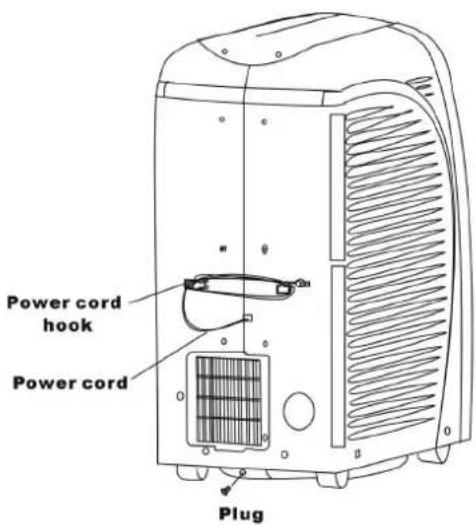
Wrap the cord around the cord hooks.
It is recommended that the unit be packed in its original carton for storage.
Store in a dry location.
TROUBLESHOOTING
Before seeking repair or service, please check the following:
| PROBLEM POSSIBLE CAUSE REMEDY | ||
| Unit does not operate or only runs in fan mode. | Is the unit plugged in? Securely plug the power cord into the wall outlet. | |
| Is the main power supply on? | Re-establish the main power supply. | |
| Is the water container full indicator light on? | Empty the water container. | |
| Is the timer set? | Change timer settings. | |
| Cooling efficiency is not satisfactory. | Is the air inlet or outlet blocked? Clear the blocking. | |
| Is there any other heat source in the room? | Move the heat source. | |
| Are the air filters dirty? | Clean the air filters. | |
| Is the temperature setting suitable? | Change the temperature setting. | |
| Is the fan speed set at low? | Increase the fan speed. | |
| Unit is noisy or vibrates. | Is the machine positioned unevenly on a level surface? | Place the unit on a level surface. |
| The unit starts and stops frequently. | Is the voltage from the power source correct? | Use a proper power source. |
| Is the exhaust hose positioned incorrectly? | Position the exhaust hose correctly and keep the exhaust hose straight as possible. | |
ERROR MESSAGES
Diagnostic system indicators appear if any of the following interrupts operation of the unit. The unit may require simple maintenance or repair by a qualified service technician.
| CODE DIAGNOSIS ACTION | ||
| FAULT E1 Faulty room temperature sensor Contact customer service for repair or service. | ||
| FAULT E2 Faulty inside sensor. Contact customer service for repair or service. | ||
| FAULT E3 Internal frost in the unit. Wait for unit to defrost | ||
| FAULT E4 Unit malfunctions. Contact customer service for repair or service. | ||
TECHNICAL SUPPORT / CUSTOMER SERVICE CONTACT
If you require Technical Support or Customer Service from Climachill, please contact us in the following way: -
Email: sales@climachill.co.uk
Telephone: 01273 803820
- TABLE OF CONTENTS
- IMPORTANT SAFEGUARDS
- PRODUCT DIAGRAM
- FRONT (PAC12)
- FRONT (PAC15)
- FRONT (PAC18)
- BACK
- ACCESSORIES
- INSTALLATION
- SELECTING THE LOCATION
- MOUNTING THE EXHAUST HOSE
- WINDOW KIT INSTALLATION
- CONTROL PANEL AND MULTI-COLOR DISPLAY (PAC12)
- CONTROL PANEL
- CONTROL PANEL AND MULTI-COLOR DISPLAY (PAC15) CONTROL PANEL
- MULTI-COLOR DISPLAY
- CONTROL PANEL AND MULTI-COLOR DISPLAY (PAC18)
- CONTROL PANEL FUNCTIONS
- FAN BUTTON
- TEMPERATURE
- TIMER
- TIME DISPLAY
- SWING
- TEMPERATURE DIAL (PAC18)
- TIMER DIAL (PAC18)
- DEHUMIDIFYING
- FAN MODE
- HEATING
- AUTO MODE
- SLEEP MODE
- REMOTE CONTROL & OPERATION (PAC15/18 ONLY)
- WATER DRAINAGE
- HIGH HUMIDITY WATER RELEASING FEATURE (PAC18)
- MAINTENANCE
- CLEANING THE HOUSING
- CLEANING THE FILTER
- END OF SEASON STORAGE
- TROUBLESHOOTING
- ERROR MESSAGES
- TECHNICAL SUPPORT / CUSTOMER SERVICE CONTACT
Brand : Climachill
Model : PAC15
Category : Air conditioner