
SM810AW - Loudspeaker Lowell - Free user manual and instructions
Find the device manual for free SM810AW Lowell in PDF.


| Product Type | Portable Speaker |
| Brand | Lowell |
| Model | SM810AW |
| Dimensions (W x H x D) | 7.9 x 4.7 x 5.1 in (200 x 120 x 130 mm) |
| Weight | 2.2 lbs (1.0 kg) |
| Power Output | 20W RMS |
| Power Supply | AC 100-240V, 50/60Hz or built-in rechargeable battery |
| Battery Life | Up to 8 hours at medium volume |
| Connectivity | Bluetooth 5.0, 3.5mm Aux-In, USB playback |
| Speaker Configuration | Full-range driver with passive radiator |
| Frequency Response | 60 Hz - 20 kHz |
| Impedance | 4 Ohms |
| Controls | Power, Volume +/-, Play/Pause, Bluetooth pairing button |
| Indicators | LED for power and Bluetooth status |
| Material | ABS plastic with fabric grille |
| Water Resistance | IPX5 (splash proof) |
| Included Accessories | USB charging cable, 3.5mm audio cable, user manual |
| Maintenance | Wipe with a soft, dry cloth. Do not use harsh chemicals. |
| Safety Precautions | Do not expose to extreme temperatures or moisture. Keep away from children. |
| Spare Parts & Repairability | Contact Lowell support for service. No user-serviceable parts inside. |
Frequently Asked Questions - SM810AW Lowell
User questions about SM810AW Lowell
0 question about this device. Answer the ones you know or ask your own.
Ask a new question about this device
Download the instructions for your Loudspeaker in PDF format for free! Find your manual SM810AW - Lowell and take your electronic device back in hand. On this page are published all the documents necessary for the use of your device. SM810AW by Lowell.
USER MANUAL SM810AW Lowell
Electrical and Acoustical Specifications
| Model Number | Model Type | Driver Type | Frequency Response | Sensitivity (70V/1W/1M) | Dispersion (-6dB@2kHz Oct.) | Transformer Taps Switch |
| SM810A | Black With Hangers | #810 8" Dual Cone | 117Hz-6.9kHz ± 7dB | 97.1dB | 115 Degrees Conical | 1/4W @ 70V 1/2W @ 70V 1W @ 70V 2W @ 70V 4W @ 70V |
| SM810AW | White With Hangers | |||||
| SM810A-BR | Black, Factory Installed Rails | |||||
| SM820A | Black With Hangers | #8A50 8" Coaxial | 60Hz-16.5kHz ± 7dB | 90.6dB | 100 Degrees Conical | “Off” Switch Position Is Also Available |
| SM820AW | White With Hangers | |||||
| SM820A-BR | Black, Factory Installed Rails | |||||
| SM410A | Black With Hangers | #JR410 4" Single Cone | 85Hz-12.6kHz ± 7dB | 92.1dB | 170 Degrees Conical | |
| SM410AW | White With Hangers | |||||
| SM410A-BR | Black, Factory Installed Rails |
GENERAL SIGNALING EQUIPMENT

LISTED
4M24
UL1480 5th EDITION GENERAL SIGNALING CSA C22.2 NO. 205-M1983, UL2043 SUITABLE FOR USE IN PLENUM SPACES
Mounting Note:
The speaker system must be mounted in accordance with local, state, and federal codes and regulations, and industry standard practices.
1
natural_image
Black electronic device with a perforated ventilation grille and power outlet (no visible text or symbols)2

natural_image
Hand holding a black electronic device with wires and a fan, no visible text or symbols
natural_image
Black rectangular device with white cables and a small meter on top, placed on a plain surface (no visible text or symbols)4
natural_image
Black rectangular electronic device with white wire mesh and a small label on the front (no readable text or symbols)Design Note: Sound masking speakers are typically mounted above the finished ceiling in the plenum space. In most installations, the sound masking speakers are installed with the bottom of the enclosure roughly 1' above the finished ceiling with the speaker aiming upward so the masking noise bounces off of the slab or deck above. When the plenum space is taller than 6', the designer may decide that the sound masking speakers should be installed at 6' or more above the finished ceiling aiming downward. In some instances, plenum spaces crowded with many obstructions may require that the speakers be mounted sideways aiming between the obstructions. For other applications, the designer may choose to rest the masking speakers directly on the lay-in tile ceiling grid. The exact mounting position of the masking speakers dramatically affects the dispersion of the sound masking noise. This installation sheet has been written under the assumption that a qualified consultant or designer has pre-determined the speaker spacing and mounting orientation that will result in the desired sound masking noise coverage.
For models SM810A-BR, SM820A-BR, and SM410A-BR skip to step
6
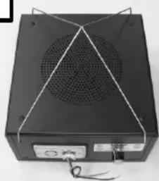
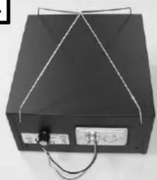
1 As shipped from the factory, the masking speaker hangers are configured for aiming the speaker upward. Unfold the speaker hangers as shown.
2 To install the masking speakers aiming sideways or aiming down, it is necessary to remove the hangers. To remove and reinstall the hangers, always rotate the hanger to the 45 degree position as shown. Note: If placing the speakers under a computer floor or on a shelf, remove and discard the hangers.
3 To install the speaker aiming sideways, remove the hangers by rotating them to the 45 degree position. Relocate the hangers to the 45 degree position in the new location and reinsert the hangers as shown.
4 To install the speaker aiming downward, remove the hangers by rotating them to the 45 degree position. Relocate the hangers to the 45 degree position in the new location and reinsert the hangers as shown.

5 Use the two (2) "S" hooks and four (4) foot piece of chain supplied with the masking speaker to suspend the speaker from the building structure. Hanging point hardware to attach the chain to the building structure will be furnished by the installer.
Skip to step 8.
6 Speaker models SM810A-BR, SM820A-BR, and SM410A-BR are shipped from the factory without hanging brackets, "S" hooks, or chain, because these models are shipped with factory installed SM-BR rails. SM-BR Bridge Rail Kits (sold separately) can be mounted in the field to any of the models that are shipped with hangers and chain. To mount the rails to the enclosure, remove and discard the hangers (see step 2 on page 1). Place the masking speaker face down. Locate the six (6) pilot holes in the rear of the speaker enclosure and six (6) holes on either end of the rails. Use the six (6) Phillips head screws provided to attach the rails to the bottom of the masking speaker as shown.
7 Place the masking speaker with the bridge rails attached above the finished ceiling across the tile grid as shown.
Important Note: Depending upon local codes and regulations, it may be required to attach the bridge rails to the ceiling tile grid. Holes in the ends of the bridge rails have been provided so that sheet metals screws (provided by the installer) can attach the rails to the grid. Also depending upon local codes and regulations, it may be required for the installer to attach earthquake restraint cables to the masking speaker. Holes in the vertical flanges at the ends of the rails are provided for earthquake restraint cables (furnished by the installer).
8 UL recognized wire nuts or crimp type connectors (provided by the installer) may be used to make a simple splice to the provided positive red (+) and common black (-) input wires. After making that splice, loosen the Romex connector screws and insert the splice into the masking speaker through the Romex connector. Tighten down the Romex connector clamp to provide strain relief for the input cable. A cable to the next speaker in the string may be wired in parallel with the incoming speaker wire as shown.
9 The input wiring splice should always be permanently located inside of the masking speaker wiring cavity and not in open space outside of the input plate.
Note: To attach an additional Romex connector or to mount other conduit fittings for flexible conduit, the input plate can be removed from the masking speaker. Two (2) combination 12 & 34 knock-outs are provided on the input wiring cavity cover plate. The additional Romex connector or flexible conduit and fittings will be furnished by the installer.
10 A transformer tap selector switch is provided on the side of the masking speaker enclosure. “OFF” and 70V 1/4W, 1/2W, 1W, 2W, and 4W select positions are provided. The transformer tap switch is set at 1W when shipped from the factory. Set the selector switch as specified by the system designer.

Brand : Lowell
Model : SM810AW
Category : Loudspeaker