
LUH-15TA - Loudspeaker Lowell - Free user manual and instructions
Find the device manual for free LUH-15TA Lowell in PDF.


| Product Type | Re-entrant horn speaker |
| Model | LUH-15TA |
| Brand | Lowell |
| Power Rating (RMS) | 15W |
| Frequency Response | 740Hz – 704kHz ± 6dB |
| Sensitivity (1W/1M) | 105dB |
| Max SPL (15W/1M) | 116.8dB |
| Conical Dispersion | 80 degrees @ 2kHz octave |
| Input Impedance (nominal) | 5000, 2500, 1300, 666, 333, 133, 89, 45 ohms |
| Voltage Input | 25V, 70V, 100V selectable taps, also 8 ohm direct |
| Transformer Power Taps | 25V: .13W, .25W, .50W, 1.0W, 1.9W, 4.7W, 7.5W, 15W; 70V: 1.0W, 2.0W, 3.8W, 7.5W, 15W; 100V: 2.0W, 4.0W, 7.5W, 15W |
| Housing Material | Cast aluminum with gasketed rear cover |
| Grille Material | Perforated aluminum, press-fit with trim ring |
| Dimensions (Horn housing) | 7.1 in (180 mm) dia. housing, 8.0 in (203 mm) dia. face x 3.72 in (94 mm) depth |
| Dimensions (with trim ring/grille) | 7.1 in (180 mm) dia. housing with 9.6 in (244 mm) dia. trim ring/grille x 3.30 in (84 mm) depth x 0.772 in (19 mm) proj. |
| Mounting Bolt Circle | 7.625 in (194 mm) with 4 holes for E.I.A. 8 in speaker grille |
| Cutout Diameter | 7.25 in (184 mm) |
| Weight | 4.9 lbs (2.22 kg) |
| Mounting Options | Exposed, recessed (drywall, drop tile, masonry), surface-mount with optional backboxes and brackets |
| Accessories Included | Press-fit mesh grille with trim ring, mounting dogs |
| Optional Accessories | LUH-BRKT bracket, LUH-VRG vandal-resistant grille, LUH-BOX/BOX-INT backboxes, LUH-TP trim plate, LUH-RIB rough-in bridge, LUH-TBAR tile bridge |
| Certifications | UL 1480A, CSA C22.2 No. 205-12 (outdoor wet use), UL 2043 (plenum) |
| Environmental Rating | Indoor/outdoor (when exposed without backbox; some accessories indoor only) |
| Wiring | Red/black pigtail for 25V/70V/100V; jumper removal for 8 ohm |
Frequently Asked Questions - LUH-15TA Lowell
User questions about LUH-15TA Lowell
0 question about this device. Answer the ones you know or ask your own.
Ask a new question about this device
Download the instructions for your Loudspeaker in PDF format for free! Find your manual LUH-15TA - Lowell and take your electronic device back in hand. On this page are published all the documents necessary for the use of your device. LUH-15TA by Lowell.
USER MANUAL LUH-15TA Lowell
I-LUH (Rev. 9/30/19): Instructions for Unihorn™ Models LUH-15TA and LUH-15TX
The Unihorn ^® is a re-entrant horn engineered for general voice communications systems. While all Unihorn models feature cast aluminum housing suitable for indoor or outdoor applications when mounted exposed (without an accessory backbox), note that some accessories are not suitable for outdoor use.
MODEL SELECTION

natural_image
Exterior view of a white ceiling lamp with exposed circuitry and a circular cover (no text or symbols visible)LUH-15TA includes:
• 15W driver with transformer and tap selector
• Cast aluminum housing with mounting dogs
- Press-fit mesh grille with trim ring
Model LUH-15TA offers the greatest flexibility for 25V, 70V, 100V, or 8 ohm applications, as it includes a press-fit mesh grille and trim ring that can be mounted or not, according to the needs of the project. The grille adds a finished look, while protecting the front of horn from nesting birds and insects. The housing features mounting dogs for quick installation.
| Location | Application | Accessories (required) | Accessories (optional) |
| Indoor | Exposed | LUH-BRKT (bracket) or custom rigging hardware | |
| Recessed (existing drywall) | ---- LUH-VRG (grille) | ||
| Recessed (before drywall is installed) | LUH-RIB (rough-in bridge) | ||
| Recessed (drop tile ceiling) | LUH-TBAR (t-bridge) | ||
| Recessed (masonry) | LUH-BOX-INT (backbox) & LUH-TP (trim plate) | ||
| Surface-mount | LUH-BOX-INT (backbox) | ||
| Outdoor | Exposed | LUH-BRKT (U-bracket) or custom rigging hardware | |
| Recessed (masonry) | LUH-BOX (backbox) & LUH-TP (trim plate) | ||
| Surface-mount | LUH-BOX (backbox) | ||
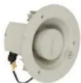
LUH-15TX includes:
• 15W driver with transformer and tap selector
- Cast aluminum housing
Model LUH-15TX is the economical choice for 25V, 70V, or 100V applications that do not require a press-fit grille, trim ring, or mounting dogs.
| Location | Application | Accessories (required) | Accessories (optional) | |
| Indoor | • Exposed | • LUH-BRKT (U-bracket) or custom rigging hardware | • LUH-VRG (grille) | |
| • Recessed (existing drywall) | • SQLK-8L (grille) & P875X-4 or P875X-6 (backbox) | • SS Series (support rails) | ||
| • Recessed (before drywall is installed) | • SQLK-8L (grille) & P875X-4 or P875X-6 (backbox) | • SS Series (support rails) | ||
| • Recessed (masonry) | • SQLK-8L (grille) & P875X-4 or P875X-6 (backbox) | ---- | ||
| • Surface-mount | • SQLK-8L (grille) & CB84 or CB86-6 (backbox) | ---- | ||
| Outdoor | • Exposed | • LUH-BRKT (bracket) or custom rigging hardware | • LUH-VRG (grille) | |
NOTE: Unihorn Models LUH-15TA and LUH-15TX may be mounted to most industry standard 8" speaker grilles. That will not void the UL Listing.
ACCESSORIES
More information and spec sheets can be found online at www.lowellmfg.com
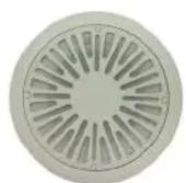
LUH-VRG
vandal-resistant grille
cast aluminum
indoor / outdoor

LUH-BOX
recessed or surface box
stainless steel
indoor / outdoor
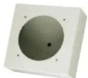
LUH-BOX-INT
recessed or surface box
cold rolled steel
indoor only
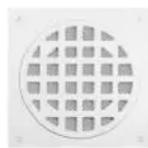
SQLK-8L
vandal-resistant security grille
cast aluminum
indoor only

P875X-4
4"D recessed box
cold rolled steel
indoor only

P875X-6
6"D recessed box
cold rolled steel
indoor only

LUH-BRKT
aluminum U-bracket &
stainless steel hardware
indoor / outdoor

LUH-TP
trim plate
aluminum
indoor / outdoor

LUH-RIB
rough-in bridge
steel
indoor only

LUH-TBAR
tile bridge
galvanized steel
indoor only

CB84
4"D surface box
cold rolled steel
indoor only

CB86-6
6"D surface box
cold rolled steel
indoor only
INSTALLATION
WARNING! Speaker installation should only be performed by qualified professionals with experience and knowledge of load-rated hardware, and safe installation mounting and rigging techniques. Improperly installed equipment can result in property damage, personal injury or death, and/or liability to the installing contractor. The speaker system must be mounted in accordance with all local, state, and federal codes and regulations, and the installation must conform to industry standard practices. It is the responsibility of the installer to properly select all hardware for rigging and installation, safety and restraint cables, and to consult a licensed mechanical or structural engineer to evaluate and certify the structural integrity and safety of any mounting method and its suitability for the building structure. Lowell Manufacturing Company, its affiliates, employees, and/or independent sales representatives, are not responsible for the use, misuse, misapplication, or unsafe installation of any horn or speaker system.
NOTE: To determine speaker spacing, see the technical paper “Distributed System Speaker Spacing for the Integrator” at LowellMfg.com. An online spacing calculator is also available.

natural_image
Metallic cylindrical device with a metal bracket and mounting holes (no visible text or symbols)Exposed (with U-bracket)

natural_image
Diagram of a mechanical or electrical component with layered circular components and a small cylindrical component above (no text or symbols)Recessed in drywall

natural_image
Interior ceiling view with circular lighting fixtures and a central circular component (no visible text or symbols)Recessed in drop tile ceiling (with t-bridge)
natural_image
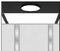
Simple diagram of a ceiling light fixture with vertical bars, no text or symbols presentRecessed before drywall installed (with rough-in bridge)

natural_image
3D mechanical assembly diagram showing components like gears and housing (no text or labels)Recessed in masonry (with backbox & trim plate)

Surface-mount (with backbox)
Model LUH-15TA
EXPOSED:
- Open Architecture (with installer-furnished hardware): Use the two threaded 1/4–20 mounting posts (on back of horn) to mount the horn with 1/4-20 threaded rods or bolts, or custom rigging hardware. Tighten the three dog ears to clamp the horn to the trim ring. Press the mesh grille into the ring to fit securely in place.
- Ceiling or Wall (with LUH-BRKT bracket): Mount the bracket to the surface. Then place the back of the horn through the trim ring and use the two threaded 1/4–20 mounting posts (on back of horn) to mount the horn to the bracket. Tighten the three dog ears to clamp the horn to the trim ring. Press the mesh grille into the ring to fit securely in place.
RECESSED: Before mounting the horn in recessed applications, be sure to check for obstructions behind the ceiling or wall. For more information, see the technical paper online at https://www.lowellmfg.com/wp-content/uploads/Checking_above_the_ceiling_before_you_cut.pdf
- Existing Drywall: Use the inside of the trim ring to trace a 7.25" diameter mounting hole in the ceiling (or wall). Cut the hole. Place the back of the horn through the trim ring and into the mounting hole, aligning tapped holes on the ring with those in the lip of the horn. Holding the horn flush against the ceiling (or wall), tighten the three mounting dogs to clamp the horn to the ring. Press the mesh grille into the ring to fit securely in place.
- Drop Tile Ceiling (with LUH-TBAR tile bridge): The tile-bridge distributes the weight of the speaker to the ceiling grid, which will help prevent sagging. Begin by removing the ceiling tile and placing the bridge on the back of the tile to mark where the mounting hole should be cut. Cut the 7.25" mounting hole, then replace the tile in the ceiling grid with the bridge sitting on top of it. Place the back of the horn through the trim ring and into the mounting hole. Holding the horn flush against ceiling tile, tighten the three dog ears on the back of the horn to clamp it to the trim ring, tile and bridge. Press the mesh grille into the ring to fit securely in place.
- New Construction
— Before Drywall is Installed (with LUH-RIB rough-in bridge): Reserve space for the horn by mounting a rough-in bridge to the framing, positioning the bridge so the return lip protrudes into the room. The drywaller uses the lip as a guide to trace the mounting hole. Be sure to install wiring so it can be accessed when drywall is in place. After drywall is installed and painted, mount the horn by placing the back of it through the trim ring and into the mounting hole. Holding the horn flush to the ceiling (or wall), tighten the horn's three dog ears to clamp it to the bridge and trim ring. Then press the mesh grille into the ring so it fits securely in place.
— Exterior Masonry (with LUH-BOX backbox and LUH-TP trim plate): Run speaker wire into the backbox, then mount the box in the wall using mortar to hold it in place. After the mortar dries, mount the trim plate to the front of the backbox using four 8-32 screws (provided). The trim plate is larger than the backbox so it will cover rough mortar edges. Place the back of horn through the trim ring and into the box. Tighten the three dog ears to clamp the horn to the backbox and ring. Press the mesh grille into the ring to fit securely in place.
— Interior Masonry (with LUH-BOX-INT backbox): Run speaker wire into the backbox, then mount the box in the wall using mortar to hold it in place. After the mortar dries, mount the trim plate to the front of the backbox using four 8-32 screws (provided). The trim plate is larger than the backbox so it will cover rough mortar edges. Place the back of horn through the trim ring and into the box. Tighten the three dog ears to clamp the horn to the backbox and ring. Press the mesh grille into the ring to fit securely in place.
SURFACE-MOUNT:
- Exterior Surface (with LUH-BOX backbox): Run speaker wire into backbox, then mount backbox to surface. Place back of horn through trim ring and into backbox. Tighten three dog ears to clamp horn to backbox and trim ring. Press the fine mesh grille into the trim ring so it fits securely in place.
- Interior Surface (with LUH-BOX-INT backbox): Run speaker wire into backbox, then mount backbox to surface. Place back of horn through trim ring and into backbox. Tighten three dog ears to clamp horn to backbox and trim ring. Press the fine mesh grille into the trim ring so it fits securely in place.
Model LUH-15TX
EXPOSED
- Open Architecture (with installer-furnished hardware): Use the two threaded 1/4–20 mounting posts on back of horn to mount horn using 1/4-20 threaded rods or bolts, or custom rigging hardware.
- Ceiling or Wall (with LUH-BRKT bracket): Mount bracket to surface. Use the two threaded 1/4–20 mounting posts on back of horn to mount the horn to bracket.
RECESSED
Before mounting the horn in recessed applications, be sure to check for obstructions behind the ceiling or wall. For more information, see the technical paper online at https://www.lowellmfg.com/wp-content/uploads/Checking_above_the_ceiling_before_you_cut.pdf
- Existing Drywall (with SQLK-8L grille and P875X-4 or P875X-6 backbox): Cut hole in ceiling or wall according to instructions on backbox. Run speaker wire into box and recess-mount box into wall. Mount SQLK-8L grille to horn and attach assembly to backbox.
SURFACE-MOUNT
- Interior Surface (with SQLK-8L grille and CB84 or CB86 backbox): Run speaker wire into backbox and mount to surface. Mount SQLK-8L grille to horn and attach assembly to backbox.
WIRING & SCHEMATICS
Model LUH-15TA & LUH-15TX: Horn ships with pigtail exiting a waterproof connector. The red wire is the positive (+) conductor and the black wire is the negative (−) conductor. The pigtail has been factory-connected to the 25V/70V/100V input terminals inside of the termination compartment. A splice can be made to the pigtail, using UL-approved splice connectors, if the splice is made inside a UL recognized junction box (ex. Lowell LUH-BOX). If a UL-approved junction box is not used, the waterproof fitting should be loosened, the pigtail should be disconnected and removed, the field wiring should be fed through the waterproof connector, and the termination should be made directly to the input terminals in the termination compartment. The waterproof fitting should then be tightened. Note that to maintain a UL-required seal at the waterproof fitting, the field wiring used must have a round jacket with a diameter of 0.197" to 0.354".
For 8-ohm connection, remove the jumper on the upper 8-ohm terminal strip, and terminate the input wiring on the positive (+) and negative (−) 8-ohm terminals. This bypasses the transformer and selector switch as shown on the schematic below.

HORN SPECIFICATIONS
| Model No. LUH-15TA and LUH-15TX | |
| Power Rating (per EIA standard RS 426-B) 15W RMS | |
| Frequency Response 740Hz–704kHz ± 6dB | |
| Sensitivity (using 70V inputs) 105dB 1W/1M | |
| Calculated Max. SPL (based on power rating & measured sensitivity) 116.8dB 15W/1M | |
| Conical Dispersion 80 degrees @ 2kHz octave | |
| Input Impedance (nominal) 5000, 2500, 1300, 666, 333, 133, 89, 45 ohms | |
| Transformer Power Taps 25V@ .13W, .25W, .50W, 1.0W,1.9W, 4.7W, 7.5W, 15W70V@ 1.0W, 2.0W, 3.8W, 7.5W, 15W100V@ 2.0W, 4.0W, 7.5W, 15W | |
| Voltage Input | 25V, 70V, or 100V selectable taps |
*Measured in Lowell audio lab.
**UL measured A weighted reverberant room sound power output.
***3dB increment rating with a sweep sine-wave signal source flat weight SPL meter.
PHYSICAL ATTRIBUTES
Outside Dimensions
Horn housing....7.1 in. (180 mm) dia. housing with 8.0 in. (203 mm) dia. face x 3.72 in. (94 mm) depth
Horn, trim ring, grille.....7.1 in. (180 mm) dia. housing with 9.6 in. (244 mm) dia. trim ring/grille x 3.30 in. (84 mm) depth x 0.772 in. (19 mm) proj.
Material Cast aluminum housing with gasketed rear cover; cast aluminum trim ring; perforated aluminum grille
Mounting Bolt Circle ......7.625 in. (194 mm) with 4 holes spaced to mount an E.I.A. 8 in. speaker grille
Cutout Diameter .....7.25 in. (184 mm)
Weight ...... Model LUH-15TA = 4.9 lbs. (2.22 kg)
...... Model LUH-15TX = 4.1 lbs. (1.86 kg)
SELECTOR SWITCH VALUES
| Switch Position | Nominal Impedance | Watts @25V | Watts @70V | Watts @100V |
| 1 | 5000 | .13 | 1.0 | 2.0 |
| 2 | 2500 | .25 | 2.0 | 4.0 |
| 3 | 1300 | .50 | 3.8 | 7.5 |
| 4 | 666 | 1.0 | 7.5 | 15 |
| 5 | 333 | 1.9 | 15 | X |
| 6 | 133 | 4.7 | X | X |
| 7 | 89 | 7.5 | X | X |
| 8 | 45 | 15 | X | X |
| X=DO NOT USE. Switch positions 6, 7, 8 (for 70V applications) and 5, 6, 7, 8 (for 100V applications) will exceed the power handing capacity of the driver and transformer and could destroy the driver, transformer and/or amplifier. | ||||

Listed for UL1480A, CSA C22.2 No. 205-
12 General Signaling for outdoor wet use.
UL2043 for use in return air plenum space.

Brand : Lowell
Model : LUH-15TA
Category : Loudspeaker