
SC200 - Disk array DELL - Free user manual and instructions
Find the device manual for free SC200 DELL in PDF.


| Product Type | Disk Array (Storage Enclosure) |
| Model | Dell PowerVault SC200 |
| Form Factor | 2U Rackmount |
| Drive Bays | 12 x 3.5-inch SAS/SATA (hot-swappable) |
| Max Capacity | Up to 120 TB (with 10 TB drives) |
| Expansion | Supports daisy-chaining via SAS (up to 8 enclosures) |
| Connectivity | Dual SAS (Mini-SAS HD, 6 Gbps per port) |
| Power Supply | Dual redundant, 580W hot-plug units |
| Cooling | Dual redundant, hot-swappable fan modules |
| Management | SNMP, Web interface, Storage Manager software |
| RAID Support | Pass-through to host controller (supports RAID via host) |
| Dimensions (H x W x D) | 3.44 x 17.52 x 19.05 inches (87.3 x 444.5 x 484 mm) |
| Weight | Approximately 23 kg (50.7 lbs) fully loaded |
| Operating Temperature | 10°C to 35°C (50°F to 95°F) |
| Recommended Usage | Enterprise storage, backup, archiving, virtualization |
| Maintenance & Cleaning | Wipe exterior with a dry, lint-free cloth; do not use liquids |
| Safety | Ensure proper grounding; never remove covers when powered on |
| Spare Parts & Repairability | Field-replaceable units: PSU, fans, drives, SAS modules |
| General Info | Designed for Dell PowerEdge servers; compatible with MD3 series controllers |
Frequently Asked Questions - SC200 DELL
User questions about SC200 DELL
0 question about this device. Answer the ones you know or ask your own.
Ask a new question about this device
Download the instructions for your Disk array in PDF format for free! Find your manual SC200 - DELL and take your electronic device back in hand. On this page are published all the documents necessary for the use of your device. SC200 by DELL.
USER MANUAL SC200 DELL
Getting Started With Your System
Notes, Cautions, and Warnings

NOTE: A NOTE indicates important information that helps you make better use of your Storage Center.

CAUTION: A CAUTION indicates potential damage to hardware or loss of data if instructions are not followed.

WARNING: A WARNING indicates a potential for property damage, personal injury, or death.
Contacting Dell Technical Support Services
For technical support, go to support.dell.com/compellent/.
Information in this document is subject to change without notice. © 2012 Dell Inc. All rights reserved.
Reproduction of these materials in any manner whatsoever without the written permission of Dell Inc. is strictly forbidden.
Trademarks used in this text: Dell and the DELL logo.
Other trademarks and trade names may be used in this document to refer to either the entities claiming the marks and names or their products. Dell Inc. disclaims any proprietary interest in trademarks and trade names other than its own.
Regulatory Model Series E03J Regulatory Model Series E04J
September 2012 P/N 1C9X5 Rev. A00
Installation and Configuration

WARNING: Before performing the following procedure, review the safety instructions that came with all Storage Center components.
Unpacking the System

NOTE: Unpacking, installing, and deploying your Storage Center may be done only by a certified service technician.
Before you begin, make sure the site where you intend to set up and use the Storage Center has the following:
- Standard power from an independent source or a rack power distribution unit with a UPS.
- Storage Center with the latest firmware, BIOS, and drivers. Contact your supplier for the correct software versions.
Installation Overview
The installation process follows the general steps below. For detailed information, refer to vendor documentation supplied with the equipment.

CAUTION: If installed in a closed or multi-unit rack assembly, the operating ambient temperature of the rack environment may be greater than room ambient temperature. Therefore, consideration should be given to installing the equipment in an environment compatible with the maximum ambient temperature (Tma) specified by the manufacturer. For more information, see "Technical Specifications" on page 8.
1 Assemble the rails following the safety instructions and the rack installation instructions provided with your system.
2 Install network switches, as applicable.
3 Unpack the Storage Center controllers.
4 Unpack and install the IO cards into the Storage Center controllers.
5 Install the Storage Center controllers into the rack.
6 Unpack the enclosures.
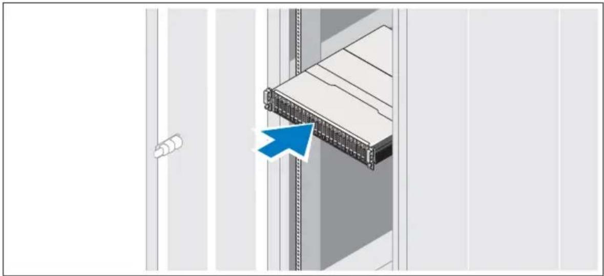
7 Install the enclosures into the rack.
• Always load the rack from the bottom up for weight stability.
- You can allow room for expansion if you have fewer than the maximum number of enclosures.
natural_image
Illustration of a server rack unit with a blue arrow pointing to its side panel (no text or symbols present)8 Unwrap and insert each drive into the enclosure one at a time.
- Protect the drive from static discharge.
• Handle drives by the edges of the frame.
△ CAUTION: If the enclosure system operates for more than a few minutes with missing drives, the enclosure can overheat, causing power failure and data loss. Such use may invalidate the warranty.
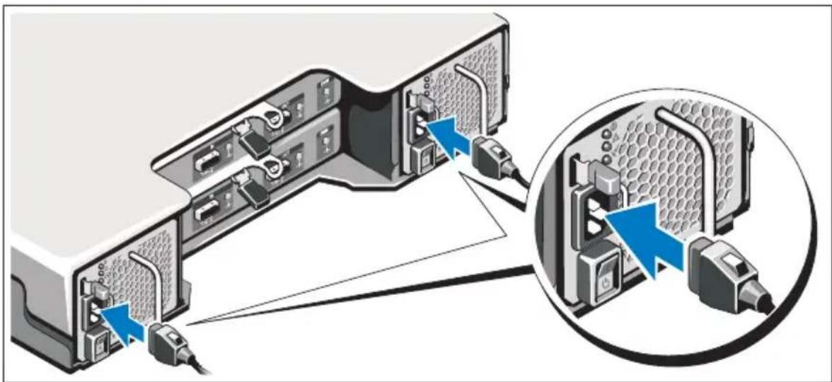
Connecting the Power Cables
natural_image
Diagram of a server rack with connected ports and cable, showing internal components and connection to a device (no text or symbols present)1 Ensure that the power switch is in the OFF position before connecting the power cables.
2 Connect the enclosure power cables to the rack power.
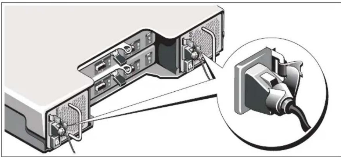
Securing the Power Cables
natural_image
Diagram of an electronic device showing internal components connected to a cable outlet, with no visible text or symbols.1 Bend the power cables as shown in the illustration and secure the cables firmly to the bracket using the strap provided.
2 Plug the other end of the power cables into a grounded electrical outlet or a separate power source such as an uninterrupted power supply (UPS) or a power distribution unit (PDU).
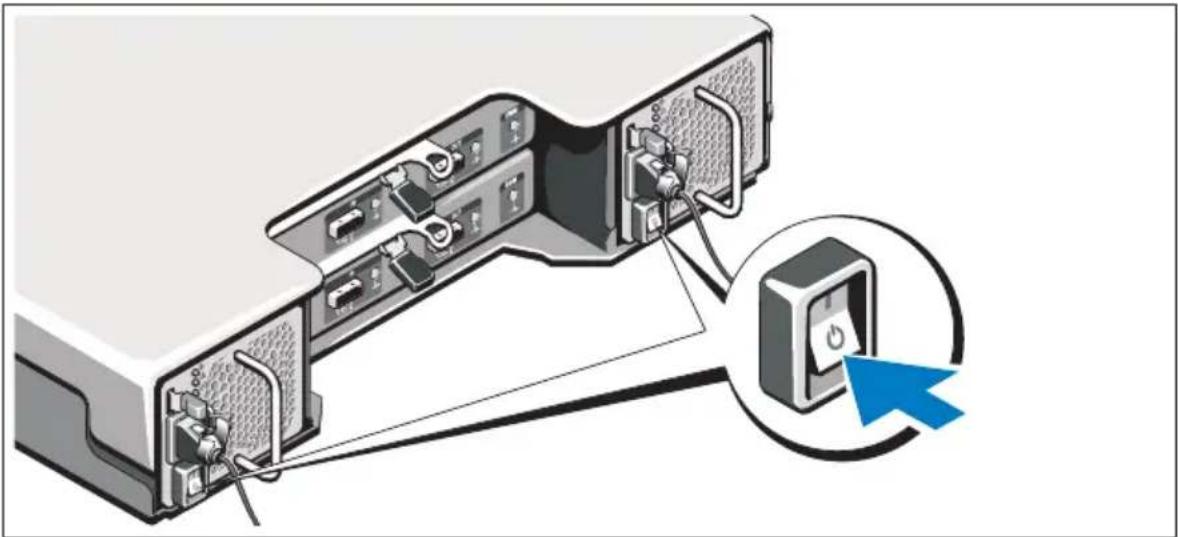
Location of Power Button
natural_image
Diagram of a computer setup showing internal components connected to a device panel with a blue cursor pointer (no text or symbols present)
NOTE: Do not power up the enclosure until all Storage Center components are racked and cabled.
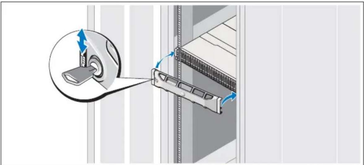
Installing the Optional Bezel
natural_image
Diagram showing a mechanical assembly with a magnified inset of a component being inserted into a housing (no text or symbols present)• Install the bezel (optional).
6 Getting Started With Your System
Other Information You May Need

WARNING: See the safety and regulatory information that shipped with your Storage Center components. Warranty information may be included within this document or as a separate document.
- The rack documentation included with your rack solution describes how to install your system into a rack.
- The Storage Center Connectivity Guide provides information about cabling all Storage Center hardware components.
- The Storage Center System Setup Guide provides instructions for configuring a new Storage Center using the System Manager Setup Wizard.
- The Storage Center System Manager Administrator's Guide describes how to manage a Storage Center.
NOM Information (Mexico Only)
The following information is provided on the device described in this document in compliance with the requirements of the official Mexican standards (NOM):
Importer: Dell Inc. de México, S.A. de C.V
Supply voltage: 100–240 V CA
Frequency: 50/60 Hz
Current consumption: 8.6 A
Technical Specifications
Drives
| SAS hard drives SC200: Up to 12 3.5-inch SAS |
| hot-swappable hard drives (6.0 Gbps) |
| SC220: Up to 24 2.5-inch SAS |
| hot-swappable hard drives (6.0 Gbps) |
Enclosure Management Modules (EMMs)
| EMMs Two hot-swappable modules with temperature sensors and an audio alarm |
Connectivity
| Configurations Storage Center supports up to 168 drivesin each redundant-path enclosure chainEach SC8000 controller supports up to 6 enclosure chains |
Redundant Array of Independent Disks (RAID)
| Controller Dell Compellent SC8000 |
| Redundant Array of Independent Disks (RAID) (continued) | |
| Management RAID management using Storage CenterSystem Manager version 6.2 or later | |
| Back-Plane Board | |
| Connectors | SC200: 12 SAS hard-drive connectorsSC220: 24 SAS hard-drive connectorsTwo power supply/cooling fan module connectorsTwo sets of EMM connectorsOne control panel connector for front LEDs |
| Sensors Two temperature sensors | |
| Back-Panel Connectors (per EMM) | |
| SAS connectors | SAS A and B connectors for connection to the controller and for expansion to an additional enclosureNOTE: SAS connectors are SFF-8086/SFF-8088 compliant |
| Serial connector One 6-pin UART mini-DIN connectorNOTE: For engineering use only | |
| LED Indicators | |
| Front panel | One two-color LED indicator for system statusOne single-color LED indicators for power status |
| Hard-drive carrier | One single-color activity LEDOne two-color LED status indicator per drive |
| EMM Three two-color LED status indicators,one each for the two EMM SAS ports and one for the EMM status | |
| Power supply/cooling fan | Three LED status indicators for power supply status, power supply/cooling fan fault status, and AC status |
Power Supplies
AC power supply (per power supply)
| Wattage | 700 W |
| Voltage | 100–240 VAC (8.6 A–4.3 A) |
Heat dissipation SC200: 191-147 W
| SC220: 133-114 W |
| Maximum inrush current | Under typical line conditions and over the entire system ambient operating range, the inrush current may reach 55 A per power supply for 10 ms or less |
Available Hard Drive Power (Per Slot)
| Supported hard drive power consumption (continuous) | SC200: Up to 1.16 A at +5 V, Up to 1.6 A at +12 V |
| SC220: Up to 1.2 A at +5 V,Up to 0.5 A at +12 V |
EMM Power (Per Slot)
| Maximum power consumed by EMM | SC200: 11 W at +12 V |
| SC220: 14 W at +12 V |
Maximum available power 100 W at +12 V
| Maximum available power | 1 W at +5 V (standby) |
Physical
Height 8.68 cm (3.41 inches)
Width 44.63 cm (17.57 inches)
| Depth | SC200: 59.4 cm (23.4 inches) |
| SC220: 54.1 cm (21.3 inches) | |
| Weight (maximum configuration) SC200: 29.2 kg (64 lb) | |
| SC220: 24 kg (53 lb) | |
| Weight (empty) | SC200: 8.84 kg (19.5 lb) |
| SC220: 8.61 kg (19 lb) | |
Environmental
NOTE: For additional information about environmental measurements for specific system configurations, see dell.com/environmental_datasheets.
| Temperature | |
| Operating | 5° to 40°C (41° to 104°F) with a maximum temperature gradation of 10°C per hourNOTE: For altitudes above 2950 feet, the maximum operating temperature is derated 1°F/550 ft. |
| Storage | -40° to 65°C (-40° to 149°F) with a maximum temperature gradation of 20°C per hour |
| Relative humidity | |
| Operating | 20% to 80% (noncondensing) with a maximum humidity gradation of 10% per hour |
| Storage | 5% to 95% (noncondensing) |
| Maximum vibration | |
| Operating | 0.26 G at 5–350 Hz for 15 min |
| Storage | 1.88 G at 10–500 Hz for 15 min |
| Maximum shock | |
| Operating | Half-sine shock 31G +/- 5% with a pulse duration of 2.6ms +/-10% in operational orientations only |
| Storage | Half-sine shock 71G +/- 5% with a pulse duration of 2ms +/- 10% (all sides)Square wave shock 27G with a velocity change of 235 in/sec (all sides) |
| Altitude | |
| Operating | -16 to 3048 m (-50 to 10,000 ft)NOTE: For altitudes above 2950 feet, the maximum operating temperature is derated 1°F/550 ft. |
| Storage | -16 to 10,600 m (-50 to 35,000 ft) |
| Airborne Contaminant Level | |
| Class | G2 or lower as defined by ISA-S71.04-1985 |
www.dell.com | support.dell.com
- Getting Started With Your System
- Notes, Cautions, and Warnings
- Contacting Dell Technical Support Services
- Installation and Configuration
- Unpacking the System
- Installation Overview
- Connecting the Power Cables
- Securing the Power Cables
- Location of Power Button
- Installing the Optional Bezel
- Other Information You May Need
- NOM Information (Mexico Only)
- Technical Specifications
Brand : DELL
Model : SC200
Category : Disk array