C7C242-CB-M - Motherboard Supermicro - Free user manual and instructions
Find the device manual for free C7C242-CB-M Supermicro in PDF.

| Product Type | Motherboard |
| Brand | Supermicro |
| Model | C7C242-CB-M |
| Form Factor | Micro-ATX |
| Dimensions (W x D) | 244 mm x 244 mm (9.6 in x 9.6 in) |
| Weight | Approximately 0.7 kg (1.5 lbs) |
| CPU Socket | LGA 1151 |
| Supported CPUs | Intel Xeon E-2100/E-2200, 8th/9th Gen Core i3/i5/i7 |
| Chipset | Intel C242 |
| Memory Slots | 4 x DIMM, DDR4 ECC up to 128 GB |
| Expansion Slots | 1 x PCIe 3.0 x16, 1 x PCIe 3.0 x8 (x4), 2 x PCIe 3.0 x4 (x2), 1 x M.2 |
| Storage Interfaces | 6 x SATA 3.0, 2 x M.2 (SATA/PCIe) |
| LAN | Dual Gigabit Ethernet (Intel i210-AT) |
| USB Ports | 2 x USB 3.1 Gen2 (rear), 6 x USB 3.0 (4 rear, 2 via header), 4 x USB 2.0 via headers |
| Video Output | Integrated BMC with VGA (Aspeed AST2500) |
| Power Connectors | 24-pin ATX, 8-pin EPS12V |
| Management | IPMI 2.0 with dedicated LAN |
| Operating Temperature | 0°C to 40°C (32°F to 104°F) |
| Maintenance | Keep free of dust; use ESD wrist strap when handling |
| Safety | Follow ESD precautions; disconnect power before servicing |
| Spare Parts & Repairability | Contact Supermicro support for replacement parts; not user-serviceable |
| General Information | Designed for entry-level servers and workstations |
Frequently Asked Questions - C7C242-CB-M Supermicro
User questions about C7C242-CB-M Supermicro
0 question about this device. Answer the ones you know or ask your own.
Ask a new question about this device
Download the instructions for your Motherboard in PDF format for free! Find your manual C7C242-CB-M - Supermicro and take your electronic device back in hand. On this page are published all the documents necessary for the use of your device. C7C242-CB-M by Supermicro.
USER MANUAL C7C242-CB-M Supermicro
C7C242-CB-M C7C242-CB-MW
USER'S MANUAL
Revision 1.0a
The information in this User's Manual has been carefully reviewed and is believed to be accurate. The vendor assumes no responsibility for any inaccuracies that may be contained in this document, makes no commitment to update or to keep current the information in this manual, or to notify any person or organization of the updates. Please Note: For the most up-to-date version of this manual, please see our web site at www.supermicro.com.
Super Micro Computer, Inc. ("Supermicro") reserves the right to make changes to the product described in this manual at any time and without notice. This product, including software and documentation, is the property of Supermicro and/or its licensors, and is supplied only under a license. Any use or reproduction of this product is not allowed, except as expressly permitted by the terms of said license.
IN NO EVENT WILL SUPERMICRO BE LIABLE FOR DIRECT, INDIRECT, SPECIAL, INCIDENTAL, SPECULATIVE OR CONSEQUENTIAL DAMAGES ARISING FROM THE USE OR INABILITY TO USE THIS PRODUCT OR DOCUMENTATION, EVEN IF ADVISED OF THE POSSIBILITY OF SUCH DAMAGES. IN PARTICULAR, SUPERMICRO SHALL NOT HAVE LIABILITY FOR ANY HARDWARE, SOFTWARE, OR DATA STORED OR USED WITH THE PRODUCT, INCLUDING THE COSTS OF REPAIRING, REPLACING, INTEGRATING, INSTALLING OR RECOVERING SUCH HARDWARE, SOFTWARE, OR DATA.
Any disputes arising between manufacturer and customer shall be governed by the laws of Santa Clara County in the State of California, USA. The State of California, County of Santa Clara shall be the exclusive venue for the resolution of any such disputes. Super Micro's total liability for all claims will not exceed the price paid for the hardware product.
FCC Statement: This equipment has been tested and found to comply with the limits for a Class B digital device pursuant to Part 15 of the FCC Rules. These limits are designed to provide reasonable protection against harmful interference when the equipment is operated in a consumer environment or residential installation. This equipment generates, uses, and can radiate radio frequency energy and, if not installed and used in accordance with the manufacturer's instruction manual, may cause harmful interference with radio communications. Operation of this equipment in a residential area is likely to cause harmful interference, in which case you will be required to correct the interference at your own expense.
California Best Management Practices Regulations for Perchlorate Materials: This Perchlorate warning applies only to products containing CR (Manganese Dioxide) Lithium coin cells. "Perchlorate Material-special handling may apply. See www.dtsc.ca.gov/hazardouswaste/perchlorate".

WARNING: This product can expose you to chemicals including lead, known to the State of California to cause cancer and birth defects or other reproductive harm. For more information, go to www.P65Warnings.ca.gov.
Manual Revision: 1.0a
Release Date: March 18, 2020
Unless you request and receive written permission from Super Micro Computer, Inc., you may not copy any part of this document.
Information in this document is subject to change without notice. Other products and companies referred to herein are trademarks or registered trademarks of their respective companies or mark holders.
Copyright © 2020 by Super Micro Computer, Inc. All rights reserved.
Printed in the United States of America
Preface
This manual is written for system integrators, PC technicians and knowledgeable PC users. It provides information for the installation and use of the SUC242-CB-M/-MW motherboard.
Manual Organization
Chapter 1 describes the features, specifications and performance of the motherboard, and provides detailed information on the Intel C242 chipset.
Chapter 2 provides hardware installation instructions. Read this chapter when installing the processor, memory modules and other hardware components into the system.
If you encounter any problems, see Chapter 3, which describes troubleshooting procedures for video, memory and system setup stored in the CMOS.
Chapter 4 includes an introduction to the BIOS, and provides detailed information on running the CMOS Setup utility.
Appendix A provides BIOS Error Beep Codes.
Appendix B lists software program installation instructions.
Appendix C contains UEFI BIOS Recovery instructions.
Checklist
Congratulations on purchasing your computer motherboard from an acknowledged leader in the industry. Supermicro boards are designed with the utmost attention to detail to provide you with the highest standards in quality and performance.
Please check that the following items have all been included with your motherboard. If anything listed here is damaged or missing, contact your retailer.
The following items are included in the retail box:
• One (1) Supermicro Motherboard
- Two (2) SATA cables
• One (1) I/O shield
• One (1) Quick Reference Guide
• One (1) Antenna (for C7C242-CB-MW only)
Conventions Used in the Manual
Special attention should be given to the following symbols for proper installation and to prevent damage done to the components or injury to yourself:

Attention! Critical information to prevent damage to the components or injury to yourself.
Important: Important information given to ensure proper system installation or to relay safety precautions.
Note: Additional Information given to differentiate various models or provides information for correct system setup.
Standardized Warning Statements
The following statements are industry-standard warnings, provided to warn the user of situations which have the potential for bodily injury. Should you have questions or experience difficulty, contact Supermicro's Technical Support department for assistance. Only certified technicians should attempt to install or configure components.
Read this section in its entirety before installing or configuring components in the Supermicro chassis.
Battery Handling

Warning!
There is a danger of explosion if the battery is replaced incorrectly. Replace the battery only with the same or equivalent type recommended by the manufacturer. Dispose of used batteries according to the manufacturer's instructions
電池の取り扱い
Ultimate disposal of this product should be handled according to all national laws and regulations.
製品の廃棄
Contacting Supermicro
Headquarters
Address: Super Micro Computer, Inc.
980 Rock Ave.
San Jose, CA 95131 U.S.A.
Tel: +1 (408) 503-8000
Fax: +1 (408) 503-8008
Email: marketing@supermicro.com (General Information)
support@supermicro.com (Technical Support)
Website: www.supermicro.com
Europe
Address: Super Micro Computer B.V.
's-Hertogenbosch, The Netherlands
Tel: +31 (0) 73-6400390
Fax: +31 (0) 73-6416525
Email: sales@supermicro.nl (General Information)
support@supermicro.nl (Technical Support)
rma@supermicro.nl (Customer Support)
Website: www.supermicro.nl
Asia-Pacific
Address: Super Micro Computer, Inc.
3F, No. 150, Jian 1st Rd.
Zhonghe Dist., New Taipei City 235
Taiwan (R.O.C)
Tel: +886-(2) 8226-3990
Fax: +886-(2) 8226-3992
Email: support@supermicro.com.tw
Website: www.supermicro.com.tw
Where to Find More Information
For your system to work properly, please follow the links below to download all necessary drivers/utilities and the user's manual for your motherboard.
Supermicro product manuals: http://www.supermicro.com/support/manuals/
Product Drivers and utilities: https://www.supermicro.com/wftp/driver/
A secure data deletion tool designed to fully erase all data from storage devices can be found at our website: https://www.supermicro.com/about/policies/disclaimer.cfm?url=/wftp/utility/Lot9_Secure_Data_Deletion_Utility/
If you have any questions, please contact our support team at support@supermicro.com.
Table of Contents
Preface
Chapter 1 Introduction
1-1 Overview 1-1
1-2 Chipset Overview 1-1
1-3 Motherboard Features 1-2
1-4 Special Features 1-4
1-5 PC Health Monitoring.... 1-4
1-6 ACPI Features 1-5
1-7 Power Supply 1-6
1-8 Super I/O 1-6
Chapter 2 Installation
2-1 Installation Components and Tools Needed 2-1
2-2 Static-Sensitive Devices.... 2-2
Precautions 2-2
Unpacking.... 2-2
2-3 Processor and Heatsink Installation.... 2-3
Installing the LGA1151 Processor 2-3
Installing a CPU Heatsink.... 2-6
Removing a Heatsink 2-7
2-4 Installing DDR4 Memory 2-8
DIMM Installation 2-8
Removing Memory Modules.... 2-8
Memory Support....2-9
Memory Population Guidelines 2-10
2-5 Motherboard Installation.... 2-11
Tools Needed.... 2-11
Location of Mounting Holes 2-11
Installing the Motherboard 2-12
2-6 M.2 Installation (optional).... 2-13
2-7 Connectors/IO Ports 2-14
Back I/O Panel 2-14
Universal Serial Bus (USB) 2-15
Ethernet Port.... 2-16
ATX PS/2 Keyboard/Mouse Port 2-16
Back Panel High Definition Audio (HD Audio) 2-17
Front Control Panel 2-18
Front Control Panel Pin Definitions 2-19
Power LED 2-19
HDD LED 2-19
NIC1 (LAN) 2-19
Reset Button 2-20
Power Button 2-20
Overheat (OH)/Fan Fail 2-20
2-8 Connecting Cables 2-21
ATX Main PWR & CPU PWR Connectors (JPW1 & JPW2) ...... 2-21
Fan Headers 2-22
Chassis Intrusion (JL1) 2-22
Speaker (JD1) 2-23
SPDIF_Out Header 2-23
Serial Port Header (COM1) 2-24
DOM PWR Connector (JSD1).... 2-25
Battery Connector 2-25
Standby Power Header (JSTBY1).... 2-26
M.2 Connectors.... 2-26
Front Panel Audio Header (AUDIO FP) 2-27
TPM/Port 80 Header 2-27
2-9 Jumper Settings 2-28
Explanation of Jumpers 2-28
JBT1 and JCMOS 2-29
Watch Dog Timer Enable/Disable 2-29
Manufacturing Mode 2-30
2-10 LED Indicators 2-31
LAN LEDs 2-31
Onboard Power LED (LED1) 2-31
2-11 Hard Drive Connections.... 2-32
SATA Connections (I-SATA0\~I-SATA5) 2-32
Chapter 3 Troubleshooting
3-1 Troubleshooting Procedures.... 3-1
3-2 Technical Support Procedures.... 3-3
3-3 Frequently Asked Questions 3-4
3-4 Battery Removal and Installation 3-5
3-5 Returning Motherboard for Service.... 3-6
Chapter 4 UEFI BIOS
4-1 Introduction 4-1
4-2 Main.... 4-3
4-3 Advanced.... 4-4
4-4 Event Logs 4-22
4-5 Security.... 4-24
4-6 Boot 4-25
4-7 Hardware Monitor 4-28
4-8 Save & Exit.... 4-30
Appendix A BIOS Error Beep Codes
A-1 BIOS Error Beep Codes ...... A-1
Appendix B Software Installation Instructions
B-1 Installing Drivers.... B-1
B-2 Configuring SuperDoctor ^® 5 B-2
Appendix C UEFI BIOS Recovery Instructions
C-1 An Overview to the UEFI BIOS....C-1
C-2 How to Recover the UEFI BIOS Image.... C-1
C-3 To Recover the Main BIOS Block Using a USB-Attached Device.... C-2
Chapter 1
Introduction
1-1 Overview
About this Motherboard
The C7C242-CB-M/-MW motherboard supports a single Intel® Xeon® E2100 series and 8th Generation Core™ i9 (Non-K only)/ i7 (8086K and 8700K are not supported)/ i5/ i3/ Pentium®/ Celeron® series processor in an LGA1151 socket. With the Intel C242 chipset built in, the C7C242-CB-M/-MW motherboard offers substantial system performance and storage capability for overclocking platforms in a sleek package. Please refer to our website (http://www.supermicro.com/products/) for processor and memory support updates.
1-2 Chipset Overview
Intel C242 Express Chipset Features
- Direct Media Interface (up 10 Gb/s transfer, Full Duplex)
• Intel Matrix Storage Technology and Intel Rapid Storage Technology
• Intel I/O Virtualization (VT-d) Support
• PCI Express 3.0 Interface (up to 8 GT/s)
• SATA Controller (up to 6Gb/sec)
• Advanced Host Controller Interface (AHCI)
1-3 Motherboard Features
| CPU | Single Intel Xeon E2100 series and 8th Generation Core i9 (Non-K only)/ i7 (8086K and 8700K are not supported)/ i5/ i3/ Pentium/ Celeron processor in an LGA1151 H4 type socket | ||
| Memory | Supports up to 64GB of unbuffered (UDIMM), ECC/ Non-ECC, DDR4 memory with speeds of up to 2666MHz | ||
| Dual-channel memory | |||
| DIMM sizes | |||
| UDIMM 4GB/8GB/16GB | |||
| Chipset | Intel C242 chipset | ||
| Expansion Slots | One (1) PCI-E 3.0 x16 slot | ||
| Three (3) PCI-E 3.0 x1 slots | |||
| One (1) M-Key M.2 2242/2260/2280 | |||
| One (1) E-Key M.2 2230 (for WiFi + BT) (C7C242-CB-MW only) | |||
| Network Connections | Intel I219V Network Controller | ||
| One (1) RJ-45 port with Link and Activity LEDs on the I/O back panel | |||
| I/O Devices Hard Drive Connections | |||
| Audio | |||
| One (1) High Definition Audio 7.1 channel connecto supported by Realtek ALC888S on the back panel | |||
| One (1) Front Panel Audio Header | |||
| Super I/O | |||
| Nuvoton NCT6792D-B | |||
| BIOS | 256Mb AMI BIOS® SPI Flash BIOS | ||
| SMBIOS 2.7, PCI F/W 3.0, ACPI 6.2, SPI dual/quad speed support, Real Time Clock wakeup | |||
| Power Configuration | ACPI Power Management (S5) | ||
| Power-on mode for AC power recovery | |||
| Health Monitoring | CPU Monitoring | ||
| Onboard monitors: +1.8V, +3.3V, +5V, +/- 12V, +3.3V Stby, +5V Stby, VBAT, HT, Memory, PCH Temperature, System Temperature, Memory Temperature | |||
| (4+2)-phase CPU switching voltage regulator | |||
| CPU Thermal Trip support | |||
| Fan Control | |||
| Three (3) 4-pin fan headers | |||
| Multi-speed fan control via onboard Super I/O | |||
| System Management | PECI (Platform Environment Configuration Interface) 2.0 support | ||
| System resource alert via SuperDoctor® 5 | |||
| SuperDoctor 5, NMI | |||
| Chassis Intrusion header and detection | |||
| Watch Dog Timer | |||
| CD Utilities | BIOS flash upgrade utility | ||
| Drivers and software for Intel C242 chipset utilities | |||
| LED Indicators | Power/suspend state | ||
| Dimensions | Micro-ATX form factor (9.6" x 9.6") (244 mm x 244 mm) | ||
1-4 Special Features
Recovery from AC Power Loss
Basic I/O System (BIOS) provides a setting for you to determine how the system will respond when AC power is lost and then restored to the system. You can choose for the system to remain powered off, (in which case you must press the power switch to turn it back on), or for it to automatically return to a power-on state. See the Advanced BIOS Setup section to change this setting. The default setting is Last State.
1-5 PC Health Monitoring
This section describes the PC health monitoring features of the board. All have an onboard System Hardware Monitoring chip that supports PC health monitoring. An onboard voltage monitor will scan these onboard voltages continuously: +1.8V, +3.3V, +5V, +/- 12V, +3.3V Stby, +5V Stby, VBAT, HT, Memory Temperature, PCH Temperature, and System Temperature. Once a voltage becomes unstable, a warning is given, or an error message is sent to the screen. The user can adjust the voltage thresholds to define the sensitivity of the voltage monitor.
Fan Status Monitor with Firmware Control
PC health monitoring in the BIOS can check the RPM status of the cooling fans. The onboard CPU and chassis fans are controlled by Thermal Management via SIO.
Environmental Temperature Control
The thermal control sensor monitors the CPU temperature in real time and will turn on the thermal control fan whenever the CPU temperature exceeds a user-defined threshold. The overheat circuitry runs independently from the CPU. Once the thermal sensor detects that the CPU temperature is too high, it will automatically turn on the thermal fans to prevent the CPU from overheating. The onboard chassis thermal circuitry can monitor the overall system temperature and alert the user when the chassis temperature is too high.

Note: To avoid possible system overheating, please be sure to provide adequate airflow to your system.
System Resource Alert
This feature is available when the system is used with SuperDoctor 5 in the Windows and Linux operating systems. SuperDoctor is used to notify the user of certain system events. For example, you can also configure SuperDoctor to provide you with warnings when the system temperature, CPU temperatures, voltages, and fan speeds go beyond predefined thresholds.
1-6 ACPI Features
ACPI stands for Advanced Configuration and Power Interface. The ACPI specification defines a flexible and abstract hardware interface that provides a standard way to integrate power management features throughout a PC system, including its hardware, operating system and application software. This enables the system to automatically turn on and off peripherals such as CD-ROMs, network cards, hard disk drives and printers.
In addition to enabling operating system-directed power management, ACPI also provides a generic system event mechanism for Plug and Play, and an operating system-independent interface for configuration control. ACPI leverages the Plug and Play BIOS data structures, while providing a processor architecture-independent implementation that is compatible with Windows 7, Windows 8, and Windows 2008 Operating Systems.
Slow Blinking LED for Suspend-State Indicator
When the CPU goes into a suspend state, the chassis power LED will start to blink to indicate that the CPU is in suspend mode. When the user presses any key, the CPU will wake up, and the LED will automatically stop blinking and remain on.
1-7 Power Supply
As with all computer products, a stable power source is necessary for proper and reliable operation. It is even more important for processors that have high CPU clock rates or overclocked processors.
This motherboard accommodates 24-pin ATX power supplies. Although most power supplies generally meet the specifications required by the CPU, some are inadequate. In addition, the 12V 8-pin power connector located at JPW2 is also required to ensure adequate power supply to the system. Also your power supply must supply 1.5A for the Ethernet ports.
Attention! To prevent damage to the power supply or motherboard, please use a power supply that contains a 24-pin and a 8-pin power connectors. Be sure to connect these connectors to the 24-pin (JPW1) and the 8-pin (JPW2) power connectors on the motherboard.
It is strongly recommended that you use a high quality power supply that meets ATX power supply Specification 2.02 or later. It must also be SSI compliant. (For more information, please refer to the web site at http://www.ssiforum.org/). Additionally, in areas where noisy power transmission is present, you may choose to install a line filter to shield the computer from noise. It is recommended that you also install a power surge protector to help avoid problems caused by power surges.
1-8 Super I/O
The Super I/O supports one high-speed, 16550 compatible serial communication port (UART). This UART includes a 16-byte send/receive FIFO, a programmable baud rate generator, complete modem control capability and a processor interrupt system. The UART provides legacy speed with a baud rate of up to 115.2 Kbps as well as an advanced speed with baud rates of 250 K, 500 K, or 1 Mb/s, which support higher speed modems.
The Super I/O provides functions that comply with ACPI (Advanced Configuration and Power Interface), which includes support of legacy and ACPI power management through an SMI or SCI function pin. It also features auto power management to reduce power consumption.
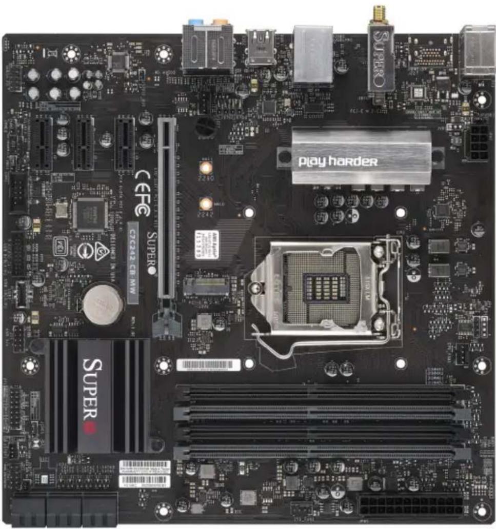
C7C242-CB-MW Motherboard Image
| Differences between C7C242-CB-MW and C7C242-CB-M | ||
| C7C242-CB-MW C7C242-CB-M | ||
| PCI-E M.2 E-Key for WiFi and Bluetooth Yes No | ||

Note: All graphics shown in this manual were based upon the latest PCB Revision available at the time of publishing of the manual. The motherboard you've received may or may not look exactly the same as the graphics shown in this manual.
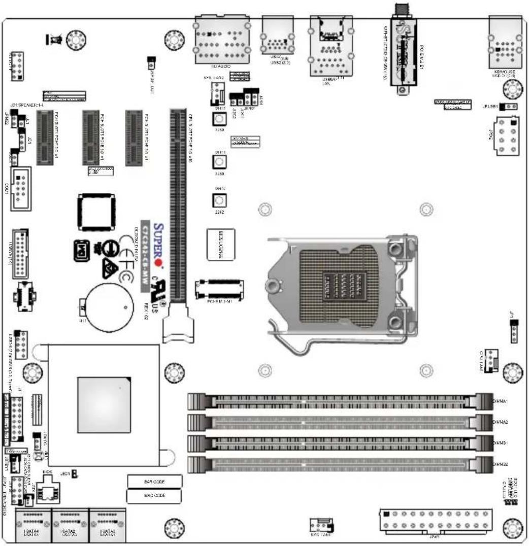
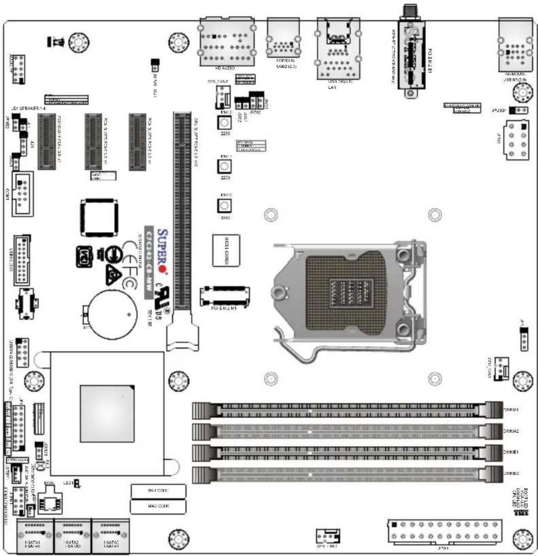
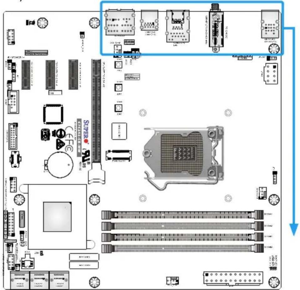
C7C242-CB-MW Motherboard Layout
| Differences between C7C242-CB-MW and C7C242-CB-M | ||
| C7C242-CB-MW C7C24 | 2-CB-M | |
| PCI-E M.2 E-Key for WiFi and Bluetooth Yes | No | |

Important Notes to the User
- See Chapter 2 for detailed information on jumpers, I/O ports and JF1 front panel connections.
- "■" indicates the location of "Pin 1".
- Jumpers not indicated are for testing only.
- When LED1 (Onboard Power LED Indicator) is on, system power is on. Unplug the power cable before installing or removing any components.
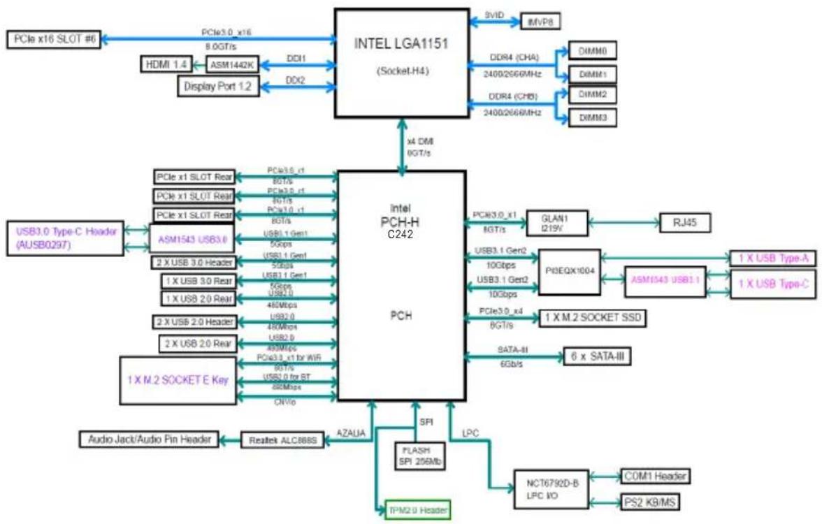
C7C242-CB-M/-MW Block Diagram
flowchart
graph TD
    A["PCIe x16 SLOT #6"] --> B["HDMI 1.4"] --> C["ASM1442K"]
    C --> D["Display Port 1.2"]
    D --> E["PCIe x10 x16 8.0GT/s"]
    E --> F["INTEL LGA1151 (Socket.H4)"]
    F --> G["DDR4 (CHA) 2400/266MHz"]
    G --> H["DIMM0"]
    G --> I["DimM1"]
    G --> J["DimM2"]
    G --> K["DimM3"]
    F --> L["PCIe x1 SLOT Rear"] --> M["PCIe x1 SLOT Rear"]
    M --> N["PCIe x1 SLOT Rear"]
    N --> O["PCIe x1 SLOT Rear"]
    O --> P["ASM1543 USB3.6"]
    P --> Q["PCIe x1 SLOT Rear"]
    Q --> R["PCIe x1 SLOT Rear"]
    R --> S["PCIe x1 SLOT Rear"]
    S --> T["PCIe x1 SLOT Rear"]
    T --> U["ASM1543 USB3.6"]
    U --> V["PCIe x1 SLOT Rear"]
    V --> W["PCIe x1 SLOT Rear"]
    W --> X["PCIe x1 SLOT Rear"]
    X --> Y["PCIe x1 SLOT Rear"]
    Y --> Z["ASM1543 USB3.6"]
    Z --> AA["PCIe x1 SLOT Rear"]
    AA --> AB["PCIe x1 SLOT Rear"]
    AB --> AC["PCIe x1 SLOT Rear"]
    AC --> AD["PCIe x1 SLOT Rear"]
    AD --> AE["ASM1543 USB3.6"]
    AE --> AF["PCIe x1 SLOT Rear"]
    AF --> AG["PCIe x1 SLOT Rear"]
    AG --> AH["PCIe x1 SLOT Rear"]
    AH --> AI["PCIe x1 SLOT Rear"]
    AI --> AJ["ASM1543 USB3.6"]
    AJ --> AK["PCIe x1 SLOT Rear"]
    AK --> AL["PCIe x1 SLOT Rear"]
    AL --> AM["PCIe x1 SLOT Rear"]
    AM --> AN["PCIe x1 SLOT Rear"]
    AN --> AO["ASM1543 USB3.6"]
    AO --> AP["PCIe x1 SLOT Rear"]
    AP --> AQ["PCIe x1 SLOT Rear"]
    AQ --> AR["PCIe x1 SLOT Rear"]
    AR --> AS["PCIe x1 SLOT Rear"]
    AS --> AT["ASM1543 USB3.6"]
    AT --> AU["PCIe x1 SLOT Rear"]
    AU --> AV["PCIe x1 SLOT Rear"]
    AV --> AW["PCIe x1 SLOT Rear"]
    AW --> AX["PCIe x1 SLOT Rear"]
    AX --> AY["PCIe x1 SLOT Rear"]
    AY --> AZ["PCIe x1 SLOT Rear"]
    AZ --> BA["PCIe x1 SLOT Rear"]
    BA --> BB["PCIe x1 SLOT Rear"]
    BB --> BC["PCIe x1 SLOT Rear"]
    BC --> BD["PCIe x1 SLOT Rear"]
    BD --> BE["PCIe x1 SLOT Rear"]
    BE --> BF["PCIe x1 SLOT Rear"]
    BF --> BG["PCIe x1 SLOT Rear"]
    BG --> BH["PCIe x1 SLOT Rear"]
    BH --> BI["PCIe x1 SLOT Rear"]
    BI --> BJ["PCIe x1 SLOT Rear"]
    BJ --> BK["PCIe x1 SLOT Rear"]
    BK --> BL["PCIe x1 SLOT Rear"]
    BL --> BM["PCIe x1 SLOT Rear"]
    BM --> BN["PCIe x1 SLOT Rear"]
    BN --> BO["PCIe x1 SLOT Rear"]
    BO --> BP["PCIe x1 SLOT Rear"]
    BP --> BQ["PCIe x1 SLOT Rear"]
    BQ --> BR["PCIe x1 SLOT Rear"]
    BR --> BS["PCIe x1 SLOT Rear"]
    BS --> BT["PCIe x1 SLOT Rear"]
    BT --> BU["PCIe x1 SLOT Rear"]
    BU --> BV["PCIe x1 SLOT Rear"]
    BV --> BW["PCIe x1 SLOT Rear"]
    BW --> BX["PCIe x1 SLOT Rear"]
    BX --> BY["PCIe x1 SLOT Rear"]
    BY --> BZ["PCIe x1 SLOT Rear"]
    BZ --> CA["PCIe x1 SLOT Rear"]
    CA --> CB["PCIe x1 SLOT Rear"]
    CB --> CC["PCIe x1 SLOT Rear"]
    CC --> CD["PCIe x1 SLOT Rear"]
    CD --> CE["PCIe x1 SLOT Rear"]
    CE --> CF["PCIe x1 SLOT Rear"]
    CF --> CG["PCIe x1 SLOT Rear"]
    CG --> CH["PCIe x1 SLOT Rear"]
    CH --> CI["PCIe x1 SLOT Rear"]
    CI --> CJ["PCIe x1 SLOT Rear"]
    CJ --> CK["PCIe x1 SLOT Rear"]
    CK --> CL["PCIe x1 SLOT Rear"]
    CL --> CM["PCIe x1 SLOT Rear"]
    CM --> CN["PCIe x1 SLOT Rear"]
    CN --> CO["PCIe x1 SLOT Rear"]
    CO --> CP["PCIe x1 SLOT Rear"]
    CP --> CQ["PCIe x1 SLOT Rear"]
    CQ --> CR["PCIe x1 SLOT Rear"]
    CR --> CS["PCIe x1 SLOT Rear"]
    CS --> CT["PCIe x1 SLOT Rear"]
    CT --> CU["PCIe x1 SLOT Rear"]
    CU --> CV["PCIe x1 SLOT Rear"]
    CV --> CW["PCIe x1 SLOT Rear"]
    CW --> CX["PCIe x1 SLOT Rear"]
    CX --> CY["PCIe x1 SLOT Rear"]
    CY --> CZ["PCIe x1 SLOT Rear"]
    CZ --> DA["PCIe x1 SLOT Rear"]
    DA --> DB["PCIe x1 SLOT Rear"]
    DB --> DC["PCH-H C242 PCH"]

    subgraph PCH
        E
        F
        G
        H
        I
        J
        K
        L
        M
        N
        O
        P
        Q
        R
        S
        T
        U
        V
        W
        X
        Y
        Z
        AA
        AB
        AC
        AD
        AE
        AF
        AG
        AH
        AI
        AJ
        AK
        AL
        AM
        AN
        AO
        AP
        AQ
        AR
        AS
        AT
        AU
        AV
        AW
        AX
        AY
        AZ
        BA
        BB
        BC
        BD
        BE
        BF
        BG
        BH
        BI
        BJ
        BK
        BL
        BM
        BN
        BO
        BP
        BPB
        BPX
        BPX
        BPX
        BPX
        BPX
        BPX
        BPX
        BPX
        BPX
        BPX
        BPX
        BPX
        BPX
        BPX
        BPX
        BPX
        BPX
        BPX
        BPX
        BPX
        BPX
        BPX
        BPX
        BPX
        BPX
        BPY
        BPY
        BPY
        BPY
        BPY
        BPY
        BPY
        BPY
        BPY
        BPY
        BPY
        BPY
        BPY
        BPY
        BPY
        BPY

    subgraph SPI
        SPi
        LPC
        LPC_IO
        LPC_IO_SA2_0 Header
        LPC_IO_SA2_0 Header
        LPC_IO_SA2_0 Header
        LPC_IO_SA2_0 Header
        LPC_IO_SA2_0 Header
        LPC_IO_SA2_0 Header
        LPC_IO_SA2_0 Header

    end

    subgraph IPM2.0 Header
        IPM2.0 Header
        IPM2.0 Header

    subgraph FlashSPI 256Mb
            FlashSPI 256Mb

            FlashSPI 256Mb -- DSPI, ALC888S, AZAUJA, ONVio, ONVio, ONVio, ONVio, ONVio, ONVio, ONVio, ONVio, ONVio, ONVio, ONVio, ONVio, ONVio, ONVio, ONVio, ONVio, ONVio, ONVio, ONVio, ONVio, ONVio, ONVio, ONVio, ONVio, ONVio, ONVie, ONVie, ONVie, ONVie, ONVie, ONVie, ONVie, ONVie, ONVie, ONVie, ONVie, ONVie, ONVie, ONVie, ONVie, ONVie, ONVie, ONVie, ONVie, ONVie, ONVie, ONVie, ONVie, ONVie, ONVie, ONVue, ONVue, ONVue, ONVue, ONVue, ONVue, ONVue, ONVue, ONVue, ONVue, ONVue, ONVue, ONVue, ONVue, ONVue, ONVue, ONVue, ONVue, ONVue, ONVue, ONVue, ONVue, ONVue, ONVue, ONVue, ONVie,
| Differences between C7C242-CB-MW and C7C242-CB-M | ||
| C7C242-CB-MW C7C242-CB-M | ||
| PCI-E M.2 E-Key for WiFi and Bluetooth Yes No | ||
C7C242-CB-M/-MW Quick Reference
| Jumper | Description | Default |
| J9701/J9702 Manufacturing Mode Pins 1-2 (Normal) | ||
| JBT1 Clear CMOS (onboard) Short the pad to clear CMOS | ||
| JCMOS Clear CMOS Jumper Open: Normal | Short: Clear CMOS | |
| JI2C1/JI2C2 SMB to PCI-E Slots Open (Disable) | ||
| JPME2 Intel Manufacturing Mode Pins 1-2 (Normal) | ||
| JPUSB1 USB Wake Up Pins 1-2 (Enable) | ||
| JWD1 Watch Dog Function Enable Pins 1-2 (RST) | ||
| Connector Description | |
| Audio FP Front Panel Audio Header | |
| BT1 Onboard Battery | |
| COM1 COM1 Header | |
| CPU_FAN1 CPU Fan Header | |
| CPU SLOT7 PCI-E 3.0 x16 PCI | Express x16 Slot |
| PCH SLOT4/5/6 PCI-E 3.0 x1 | PCI-E 3.0 x1 Slots |
| HD AUDIO High Definition Audio Ports (back panel) | |
| I-SATA0~5 SATA 3.0 Ports (6Gb/sec) | |
| JD1 Speaker/Buzzer (Pins 1-4: | ExternalSpeaker, Pins 3-4: Buzzer) |
| JF1 Front Control Panel Header | |
| JL1 Chassis Intrusion Header | |
| JPW1 24-pin ATX Main Power Connector (Required) | |
| JPW2 +12V 8-pin CPU Power Connector (Required) | |
| JSD1 SATA DOM (Disk On Module) Power Connector | |
| JSPDIF_Out | Sony/Philips Digital Interface Audio Out-put Header |
| JSTBY1 | Standby Power Header |
| JTPM1 | Trusted Platform Module (TPM) Header |
| KB/MOUSE | PS/2 Keyboard/Mouse Port |
| LAN | RJ45 GbE LAN Port |
| PCI-E M.2-E1 | PCI-E M.2 E-Key for WiFi and Bluetooth (Pre-installed, C7C242-CB-MW only) |
| PCI-E M.2-M1 | PCI-E M.2 Connector (small form factor devices and other portable devices for high speed NVMe SSDs) |
| SYS_FAN1/SYS_FAN2 System Fan Headers | |
| USB0/1 Back Panel USB 2.0 Ports | |
| USB2 Back Panel USB 2.0 Port | |
| USB3/4 Front Panel Accessible | USB 2.0 Header |
| USB5/6 | Back Panel USB 3.1 Gen 2 Ports |
| USB7 | Back Panel USB 3.1 Gen 1 Port |
| USB8/9 Front Panel Accessible | USB 3.1 Gen 1 Header |
| USB10 | Front Panel Accessible USB 3.1 Gen 1 Type-C Header |
| LED Description | Color/State | |
| BOOT LED Bootable Device POST Status | Red: OnOFF: POST Complete | |
| CPU LED CPU | POST Status Yellow: On | |
| DIMM LED DIMM POST Status | Blue: OnOFF: POST Complete | |
| LED1 | Power OnS3 (Suspend to RAM) | Green: OnGreen: Blinking |
| VGA LED Onboard VGA POST Status Green: On | ||
Chapter 2
Installation
2-1 Installation Components and Tools Needed
Screws

natural_image
Four different types of screw-like nuts, shown in different angles (no text or symbols visible)Phillips-Head Screwdriver

natural_image
Line drawing of a screwdriver with no text or symbolsIntel LGA 1151 Processor
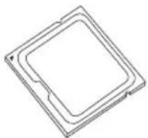
natural_image
Pure technical line drawing of a square component with rounded edges (no text or symbols)DDR4 DIMMs
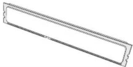
natural_image
Pure technical line drawing of a rectangular mechanical part with hatched edges (no text or symbols)PC Chassis
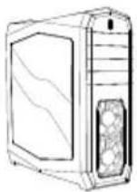
Heatsink with Fan
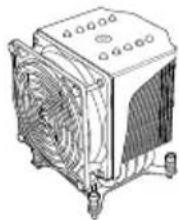
natural_image
Line drawing of a computer cooling fan with heatsink and cooling button (no text or symbols)Power Supply
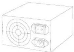
natural_image
Line drawing of a rectangular electronic device with circular ports and a small inset component (no text or symbols)Video Card (Optional)
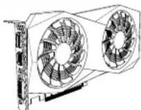
natural_image
Technical line drawing of a dual fan device (no text or symbols)SATA/USB Optical Drive (Optional)
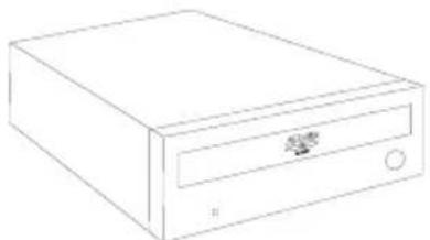
natural_image
Line drawing of a CD or DVD drive with a labeled slot (no text or symbols)SATA Hard Disk Drive
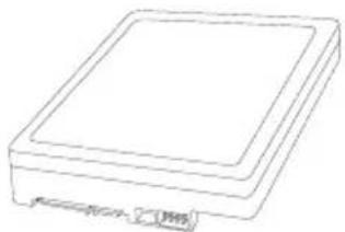
natural_image
Line drawing of a rectangular electronic device with a flat top and small base (no text or symbols)2-2 Static-Sensitive Devices
Electrostatic-Discharge (ESD) can damage electronic components. To avoid damaging your system board, it is important to handle it very carefully. The following measures are generally sufficient to protect your equipment from ESD.
Precautions
- Use a grounded wrist strap designed to prevent static discharge.
- Touch a grounded metal object before removing the board from the antistatic bag.
- Handle the board by its edges only; do not touch its components, peripheral chips, memory modules or gold contacts.
- When handling chips or modules, avoid touching their pins.
- Put the motherboard and peripherals back into their antistatic bags when not in use.
- For grounding purposes, make sure your computer chassis provides excellent conductivity between the power supply, the case, the mounting fasteners and the motherboard.
- Use only the correct type of onboard CMOS battery. Do not install the onboard battery upside down to avoid possible explosion.
Unpacking
The motherboard is shipped in antistatic packaging to avoid static damage. When unpacking the board, make sure that the person handling it is static protected.
2-3 Processor and Heatsink Installation

Attention! When handling the processor package, avoid placing direct pressure on the label area of the fan.

Important:
Always connect the power cord last, and always remove it before adding, removing or changing any hardware components. Make sure that you install the processor into the CPU socket before you install the CPU heatsink.
If you buy a CPU separately, make sure that you use an Intel-certified multi-directional heatsink only.
Make sure to install the system board into the chassis before you install the CPU heatsink.
When receiving a server board without a processor pre-installed, make sure that the plastic CPU socket cap is in place and none of the socket pins are bent; otherwise, contact your retailer immediately.
Refer to the Supermicro website for updates on CPU support.
Installing the LGA1151 Processor
- Press the load lever to release the load plate, which covers the CPU socket, from its locking position.
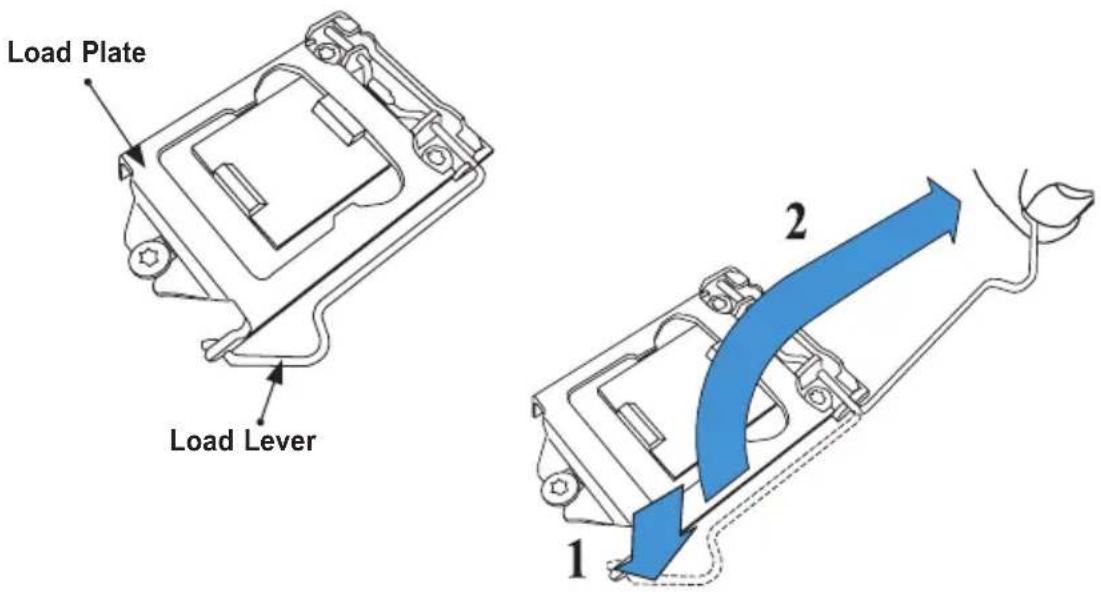
- Gently lift the load lever to open the load plate. Remove the plastic cap.
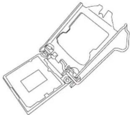
natural_image
Technical line drawing of a mechanical assembly with no visible text or symbols- Use your thumb and your index finger to hold the CPU at the North center edge and the South center edge of the CPU.
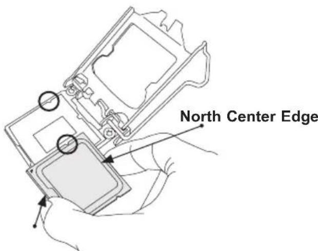
South Center Edge
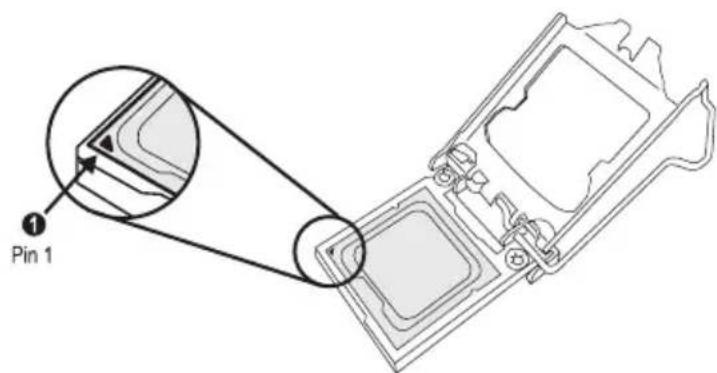
- Align the small triangle marker on the CPU to its corresponding triangle marker on the load bracket. Once it is aligned, carefully lower the CPU straight down into the socket. (Do not drop the CPU on the socket. Do not move the CPU horizontally or vertically.)
-
Do not rub the CPU against the surface or against any pins of the socket to avoid damaging the CPU or the socket.)
-
With the CPU inside the socket, inspect the four corners of the CPU to make sure that the CPU is properly installed.
-
Use your thumb to gently push the load lever down to the lever lock.
-
Close the load plate with the CPU inside the socket. Lock the "Close 1st" lever first, then lock the "Open 1st" lever second. Gently push the load levers down to the lever locks.
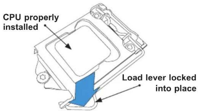
! Attention! You can only install the CPU inside the socket in one direction. Make sure that it is properly inserted into the CPU socket before closing the load plate. If it doesn't close properly, do not force it as it may damage your CPU. Instead, open the load plate again and double-check that the CPU is aligned properly.
Installing a CPU Heatsink
- Apply the proper amount of thermal grease to the heatsink.
- Place the heatsink on top of the CPU so that the four mounting holes on the heatsink are aligned with those on the retention mechanism.
- Tighten the screws in the following order:
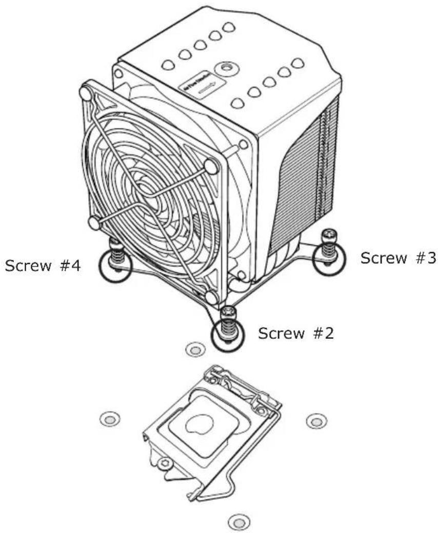
- Once the screws are tightened, plug the power cord into the CPU_FAN1 connector.

Note 1: Screw #1 is not shown in the illustration.
Note 2: Graphic drawings included in this manual are for reference only. They might look different from the components installed in your system.
Removing a Heatsink
Warning: We do not recommend that the CPU or heatsink be removed. However, if you do need to remove the heatsink, please follow the instruction below to uninstall the heatsink to avoid damaging the CPU or other components.
- Unplug the power cord from the power supply.
- Loosen the screws in the order below.
- Gently wiggle the heatsink to loosen it. Do not use excessive force when wiggling the heatsink.
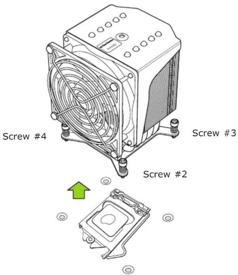
- Once the heatsink is loosened, remove it from the motherboard.

Note: Screw #1 is not shown in the illustration.
2-4 Installing DDR4 Memory

Note: Check the Supermicro website for recommended memory modules.

Attention! Exercise extreme care when installing or removing DIMM modules to prevent any possible damage.
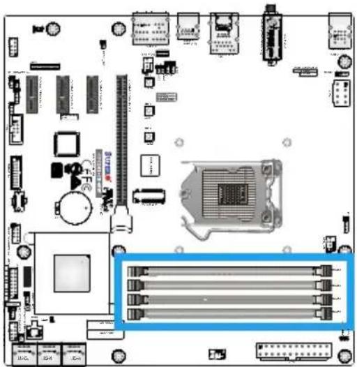
DIMM Installation
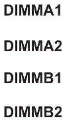
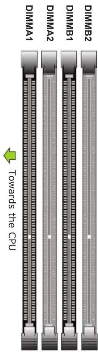
- Insert the desired number of DIMMs into the memory slots, starting with DIMMA2, then DIMMB2, DIMMA1, and DIMMB1. For the system to work properly, please use the memory modules of the same type and speed in the same motherboard.
- Push the release tab outwards on the locking end of the DIMM slot to unlock it.
- Align the key of the DIMM module with the receptive point on the memory slot.
- Align one end of the DIMM module to the receptive point on the stationary end of the slot, and the other end of the DIMM to the locking end of the slot.
- Press down on the stationary end of the slot first, then the locking end until the module snaps into place.
Removing Memory Modules
Reverse the steps above to remove the DIMM modules from the motherboard.
natural_image
Top-down view of a computer motherboard with CPU socket and connectors (no visible text or labels)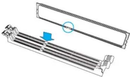
natural_image
Technical illustration of a mechanical component with a blue arrow indicating a directional change (no text or symbols present)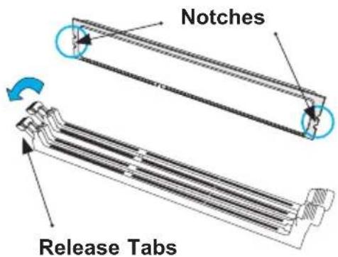

Memory Support

Towards the CPU
natural_image
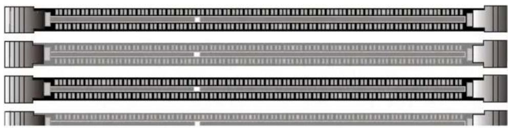
Pure electrical circuit lines without any symbolsThe C7C242-CB-M/-MW supports up to 64GB of Unbuffered (UDIMM), ECC/Non-ECC DDR4 memory up to 2666MHz in four 288-pin memory slots. Populating these DIMM modules with a pair of memory modules of the same type and size will result in interleaved memory, which will improve memory performance.

Note: Be sure to use memory modules of the same type, speed, and frequency. Mixing of memory modules of different types and speeds is not allowed.
Memory Population Guidelines
When installing memory modules, the DIMM slots should be populated in the following order: DIMMA2, DIMMB2, then DIMMA1, DIMMB1.
• Always use DDR4 DIMM modules of the same size and speed.
- Mixed DIMM speeds can be installed. However, all DIMMs will run at the speed of the slowest DIMM.
Recommended Population
| One DIMM | ○ | ● | ○ | ○ |
| Two DIMM | ○ | ● | ○ | ● |
| Four DIMM | ● | ● | ● | ● |
2-5 Motherboard Installation
All motherboards have standard mounting holes to fit different types of chassis. Make sure that the locations of all the mounting holes for both motherboard and chassis match. Although a chassis may have both plastic and metal mounting fasteners, metal ones are highly recommended because they ground the motherboard to the chassis. Make sure that the metal standoffs click in or are screwed in tightly. Then use a screwdriver to secure the motherboard onto the motherboard tray.

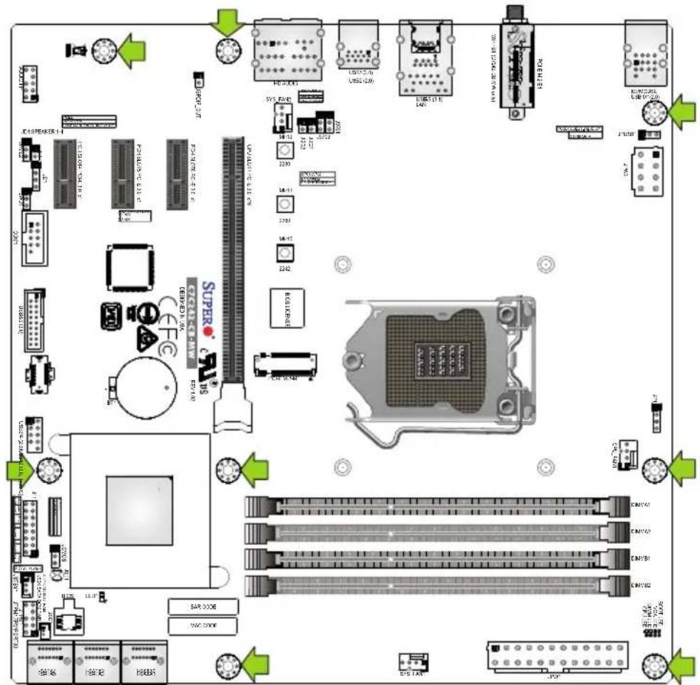
Location of Mounting Holes
! Attention! 1) To avoid damaging the motherboard and its components, please do not use a force greater than 8 lb/inch on each mounting screw during motherboard installation. 2) Some components are very close to the mounting holes. Please take precautionary measures to avoid damaging these components when installing the motherboard to the chassis.
Installing the Motherboard
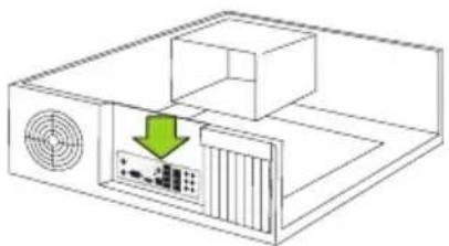
- Install the I/O shield into the back of the chassis.
natural_image
Diagram of a computer setup with a ventilation unit and a highlighted internal component (no text or symbols)- Locate the mounting holes on the motherboard. (See the previous page.)
- Locate the matching mounting holes on the chassis. Align the mounting holes on the motherboard against the mounting holes on the chassis.
- Install standoffs in the chassis as needed.
- Install the motherboard into the chassis carefully to avoid damaging other motherboard components.
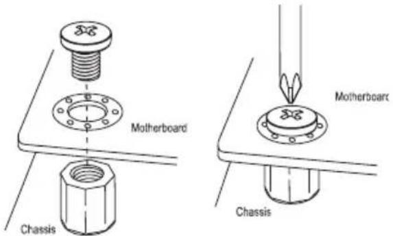
- Using the Phillips screwdriver, insert a Phillips head #6 screw into a mounting hole on the motherboard and its matching mounting hole on the chassis.
- Repeat Step 6 to insert remaining screws into all mounting holes.
- Make sure that the motherboard is securely placed in the chassis.

Note: Images displayed are for illustration only. Your chassis or components might look different from those shown in this manual.
2-6 M.2 Installation (optional)
Two M.2 (one M-key, one E-key) connectors are supported by the C7C242-CB-M/-MW. M.2 devices are used for solid state storage and internal expansion. Follow the steps below in order to install an M.2 device.
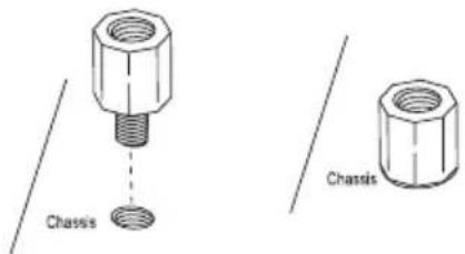
1) Locate one of two standoffs. Remove and set aside screw.
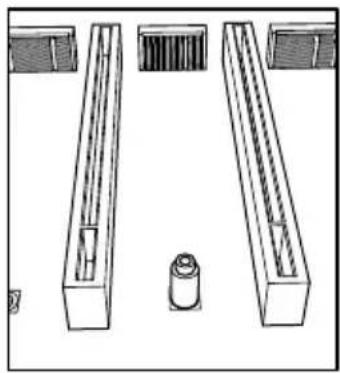
natural_image
Technical line drawing of a mechanical assembly with four components (no text or symbols)2) Plug M.2 device into M.2 connector and lower the semi-circle notched end onto standoff.
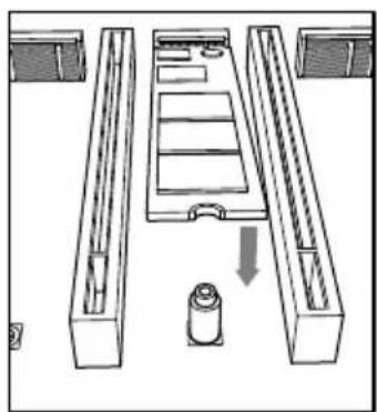
natural_image
Diagram of a mechanical assembly with three rectangular compartments and a cylindrical component, no text or symbols present3) Replace screw and tighten to secure M.2 device into place. Do not over-tighten so as to avoid damaging the M.2 device.
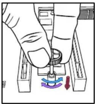
natural_image
Illustration of a hand holding a mechanical component with a blue and purple curved arrow indicating rotation (no text or symbols)2-7 Connectors/IO Ports
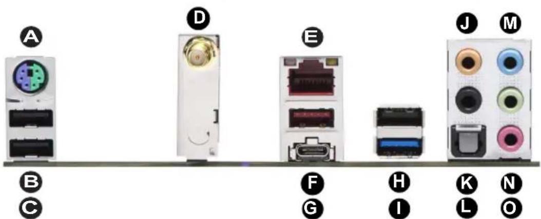
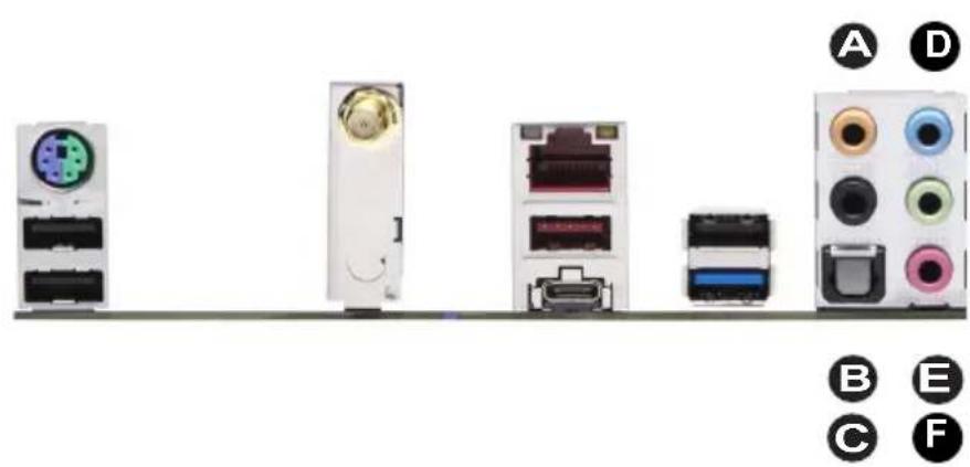
The I/O ports are color coded in conformance with the industry standards. See the figure below for the colors and locations of the various I/O ports.
Back I/O Panel
| A. PS/2 Keyboard/Mouse Port G. USB | 3.1 Gen 2 Port 6 (Type-C) M. Line | In |
| B. USB 2.0 Port 0 H. USB 2.0 Port 2 | (Type-A) N. Line Out | |
| C. USB 2.0 Port 1 I. USB 3.1 Gen 1 | Port 7 (Type-A) O. Mic In | |
| D. WiFi + BT (C7C242-CB-MW only) J. Center/LFE Out | ||
| E. RJ-45 Gigabit Ethernet Port K. Surround Out | ||
| F. USB 3.1 Gen 2 Port 5 (Type-A) L. | SPDIF Out | |
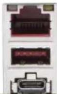
Universal Serial Bus (USB)
Three USB 2.0 ports (USB0/1/2), two USB 3.1 Gen 2 ports (USB5: Type-A, USB6: Type-C), and one USB 3.1 Gen 1 (USB7) port are on the I/O back panel. In addition, one USB 3.1 Gen 1 header (USB8/9), one USB 3.1 Gen 1 Type-C header (USB10), and one USB 2.0 header (USB3/4) are located on the motherboard to provide front chassis access using USB cables (not included). Refer to the tables below for pin definitions.
| Front Panel USB8/9 (3.1 Gen 1) Header Pin Definitions | |||
| Pin# | Definition | Pin# | Definition |
| 1 VBUS 19 Power | |||
| 2 Stda_SSRX- 18 US | B3_RN | ||
| 3 Stda_SSRX+ | 17 | USB3_RP | |
| 4 Ground | 16 | Ground | |
| 5 Stda_SSRX- 15 US | B3_TN | ||
| 6 Stda_SSRX+ | 14 | USB3_TP | |
| 7 Ground | 13 | Ground | |
| 8 D- | 12 | USB_N | |
| 9 D+ | 11 | USB_P | |
| 10 Ground | X | ||
| Front Panel USB3/4 (2.0) Header Pin Definitions | |||
| Pin# | Definition | Pin# | Definition |
| 1 +5V | 2 +5V | ||
| 3 USB_N | 4 USB_N | ||
| 5 USB_P | 6 USB_P | ||
| 7 Ground | 8 Ground | ||
| 9 Key | 10 NC | ||
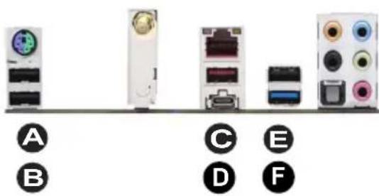

A. Back Panel USB0
B. Back Panel USB1
C. Back Panel USB5
D. Back Panel USB6
E. Back Panel USB2
F. Back Panel USB7
G. USB3/4
H. USB8/9
I. USB10
Ethernet Port
One Gigabit Ethernet port (LAN) is located on the I/O back panel to provide network connections. This port will accept RJ45 type cables.

Note: Please refer to Section 2-10 LED Indicators for LAN LED information.
| LAN PortPin Definitions | ||
| Pin# Definition Pin# Definition | ||
| 1 P2V5SB 10 SGND | ||
| 2 TD0+ 11 Act LED | ||
| 3 TD0- 12 P3V3SB | ||
| 4 TD1+ 13 Link 100 LED (Green, +3V3SB) | ||
| 5 TD1- 14 Link 1000 LED (Yellow, +3V3SB) | ||
| 6 TD2+ 15 Ground | ||
| 7 TD2- 16 Ground | ||
| 8 TD3+ 17 Ground | ||
| 9 TD3- 18 Ground | ||
ATX PS/2 Keyboard/Mouse Port
The ATX PS/2 keyboard/mouse port is located above the back panel USB ports 0/1 on the motherboard.
A. LAN Port
B. PS/2 Keyboard/Mouse Port
B
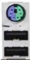

A


Back Panel High Definition Audio (HD Audio)
This motherboard features a 7.1+2 Channel High Definition Audio (HDA) codec that provides 10 DAC channels. The HD Audio connections simultaneously supports multiple-streaming 7.1 sound playback with 2 channels of independent stereo output through the front panel stereo out for front, rear, center and subwoofer speakers. Use the Advanced software included in the CD-ROM with your motherboard to enable this function.
A. Center/FLE Out
B. Surround Out
C. S/PDIF Out
D. Line In
E. Line Out
F. Mic In
natural_image
Diagram showing five electronic device components with labeled pins (A–F), no readable text or symbols beyond labelsFront Control Panel
JF1 contains header pins for various buttons and indicators that are normally located on a control panel at the front of the chassis. These connectors are designed specifically for use with Supermicro chassis. See the figure below for the descriptions of the front control panel pins and LED indicators. Refer to the following section for descriptions and pin definitions.
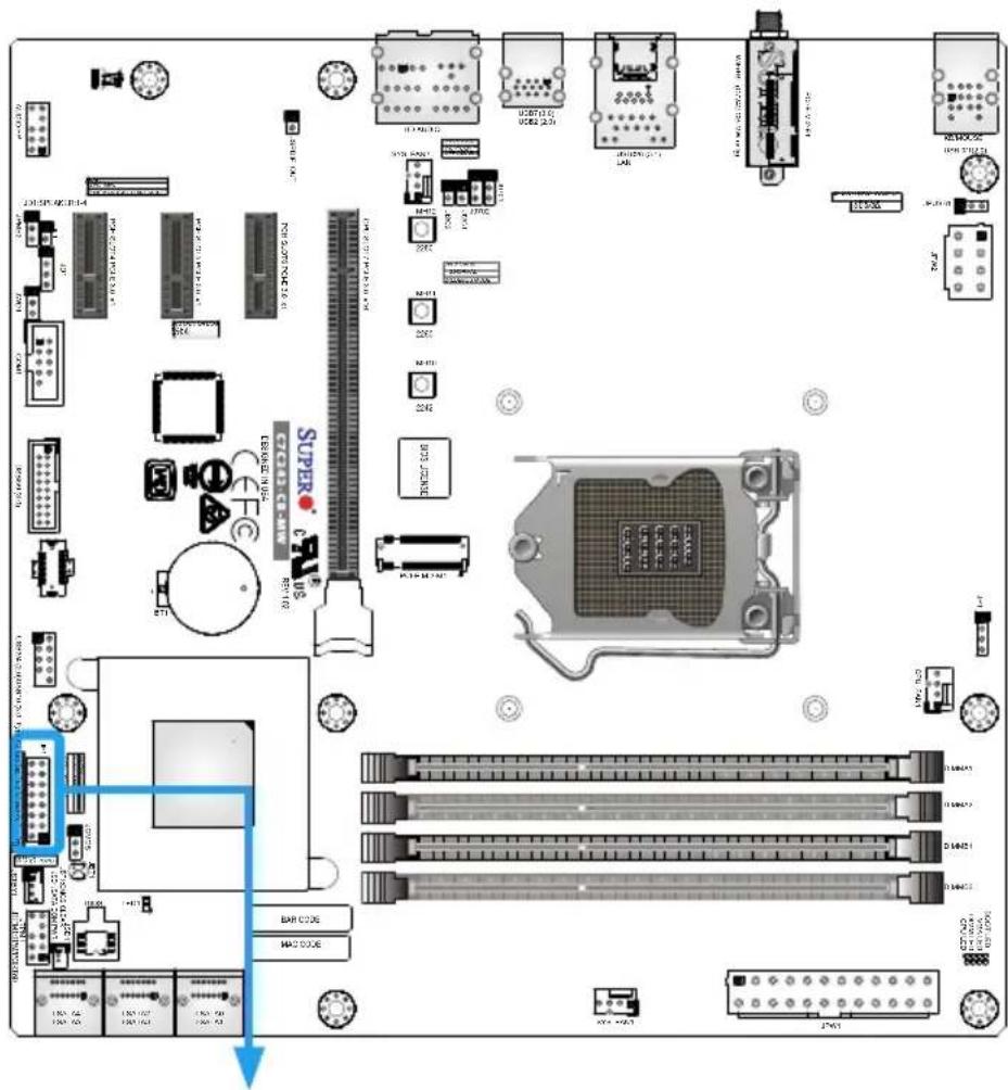
JF1 Header Pins
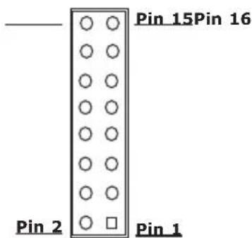
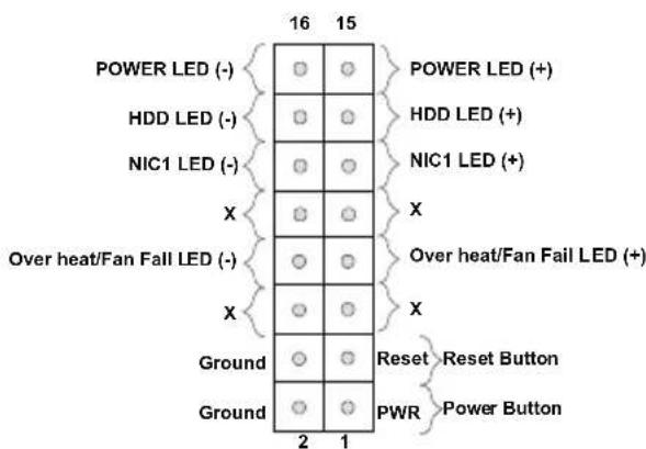
Front Control Panel Pin Definitions
Power LED
The Power LED connection is located on pins 15 and 16 of JF1. Refer to the table on the right for pin definitions.
HDD LED
The HDD LED connection is located on pins 13 and 14 of JF1. Attach a cable here to indicate the status of HDD-related activities, including IDE, SATA activities. Refer to the table on the right for pin definitions.
NIC1 (LAN)
The NIC (Network Interface Controller) LED connection for LAN port 1 is located on pins 11 and 12 of JF1. Attach an LED indicator to this header to display network activity. Refer to the table on the right for pin definitions.
| Power LEDPin Definitions (JF1) | |
| Pin# | Definition |
| 15 + 5V | |
| 16 Vcc | |
| HDD LEDPin Definitions (JF1) | |
| Pin# | Definition |
| 13 Vcc | |
| 14 HDD LED | |
| LAN LEDPin Definitions (JF1) | |
| Pin# | Definition |
| 11 Vcc | |
| 12 NIC2 | LED |
A. PWR LED
B. HDD LED
C. NIC1 LED
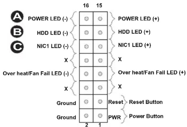
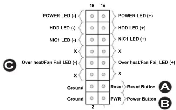
Reset Button
The Reset Button connection is located on pins 3 and 4 of JF1. Attach it to a hardware reset switch on the computer case to reset the system. Refer to the table on the right for pin definitions.
| Reset ButtonPin Definitions (JF1) | |
| Pin# | Definition |
| 3 | Reset Button |
| 4 | Ground |
Power Button
The Power Button connection is located on pins 1 and 2 of JF1. Momentarily contacting both pins will power on/off the system. This button can also be configured to function as a suspend button (with a setting in the BIOS - see Chapter 4). To turn off the power in the suspend mode, press the button for at least four seconds. Refer to the table on the right for pin definitions.
| Power ButtonPin Definitions (JF1) | |
| Pin# | Definition |
| 1 | Power Button |
| 2 | Ground |
Overheat (OH)/Fan Fail
Connect an LED cable to OH/Fan Fail connections on pins 7 and 8 of JF1 to provide warnings for chassis overheat/fan failure. Refer to the table on the right for pin definitions.
| OH/Fan Fail LEDPin Definitions (JF1) | |
| Pin# | Definition |
| 7 Vcc | |
| 8 OH/Fan Fail LED | |
| OH/Fan Fail Indicator Status | |
| State | Definition |
| Off Normal | |
| On Overheat | |
| Flashing | Fan Fail |
A. Reset Button
B. PWR Button
C. OH/Fan Fail LED
2-8 Connecting Cables
This section provides brief descriptions and pinout definitions for onboard headers and connectors. Be sure to use the correct cable for each header or connector.
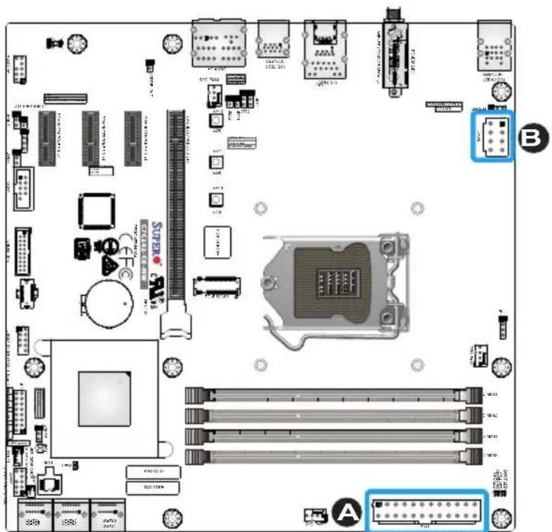
ATX Main PWR & CPU PWR Connectors (JPW1 & JPW2)
The 24-pin main power connector (JPW1) is used to provide power to the motherboard. The 8-pin CPU PWR connector (JPW2) is also required for the processor. These power connectors meet the SSI EPS 12V specification. Refer to the tables on the right and below for pin definitions.
| 12V 8-pin Power Connector Pin Definitions | |
| Pins | Definition |
| 1-4 Ground | |
| 5-8 +12V | |
(Required)
| ATX Power 24-pin Connector Pin Definitions (JPW1) | |||
| Pin# | Definition | Pin # | Definition |
| 13 +3.3V | 1 +3.3V | ||
| 14 -12V | 2 +3.3V | ||
| 15 COM | 3 COM | ||
| 16 PS_ON | 4 +5V | ||
| 17 COM | 5 COM | ||
| 18 COM | 6 +5V | ||
| 19 COM | 7 COM | ||
| 20 Res (NC) | 8 PWR_OK | ||
| 21 +5V | 9 5VSB | ||
| 22 +5V | 10 +12V | ||
| 23 +5V | 11 +12V | ||
| 24 COM | 12 +3.3V | ||
A. 24-Pin ATX Main PWR
B. 8-Pin PWR
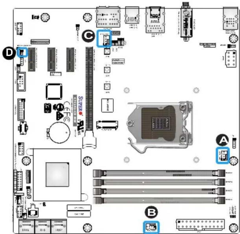
Fan Headers
The motherboard has three fan headers. These are 4-pin fan headers. Although pins 1-3 of the fan headers are backward compatible with the traditional 3-pin fans, we recommend the use 4-pin fans to take advantage of the fan speed control. This allows the fan speeds to be automatically adjusted based on the motherboard temperature. Refer to the table on the right for pin definitions.
| Fan HeaderPin Definitions | |
| Pin# | Definition |
| 1 | Ground (Black) |
| 2 | 2.5A/+12V (Red) |
| 3 | Tachometer |
| 4 | PWM_Control |
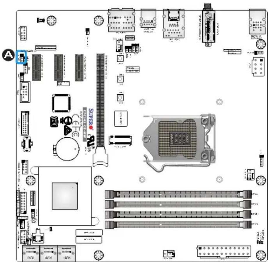
Chassis Intrusion (JL1)
A chassis intrusion header is located at JL1 on the motherboard. Attach the appropriate cable from the chassis to inform you of a chassis intrusion when the chassis is opened.
| Chassis Intrusion Header Pin Definitions (JL1) | |
| Pin# | Definition |
| 1 | Intrusion Input |
| 2 | Ground |
A. CPU_FAN1
B. SYS_FAN1
C. SYS_FAN2
D. Chassis Intrusion Header
Speaker (JD1)
On the JD1 header, pins 3 and 4 are used for internal speaker. Close pins 3 and 4 with a cap to use the onboard speaker. If you wish to use an external speaker, close pins 1-4 with a cable. Refer to the table on the right for pin definitions.
| Speaker Connector Pin Definitions | |
| Pin Setting | Definition |
| Pins 3-4 Internal Speaker | |
| Pins 1-4 External Speaker | |
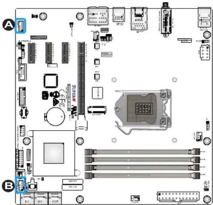
SPDIF\_Out Header
The Sony/Philips Digital Interface (JSPDIF_Out) header is used for digital audio. Place a cap on the header for audio support. You will also need to have a cable to use the connection.
A. Speaker
B. SPDIF_Out Header
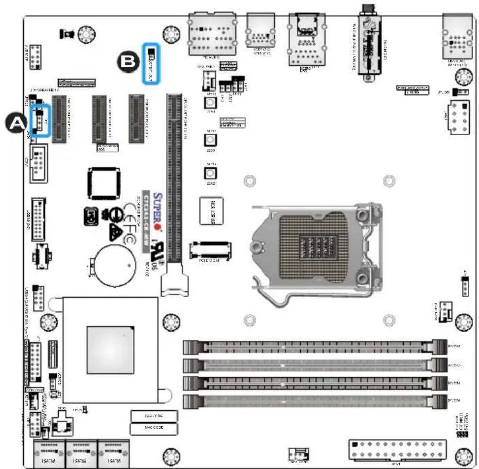
Serial Port Header (COM1)
There is one serial (COM) port header on the motherboard. COM1 is located next to the PCI-E SLOT4. Refer to the table on the right for pin definitions.
| Serial/COM Port HeaderPin Definitions | |||
| Pin# | Definition | Pin# | Definition |
| 1 DCD | 6 DSR | ||
| 2 RXD | 7 RTS | ||
| 3 TXD | 8 CTS | ||
| 4 DTR | 9 RI | ||
| 5 Ground | 10 N/A | ||
A. COM1
DOM PWR Connector (JSD1)
The Disk-On-Module (DOM) power connector, located at JSD1, provides 5V power to a solid state DOM storage device connected to one of the SATA ports. Refer to the table on the right for pin definitions.
| DOM PWRPin Definitions | |
| Pin# | Definition |
| 1 | 5V |
| 2 Ground | |
| 3 Ground | |
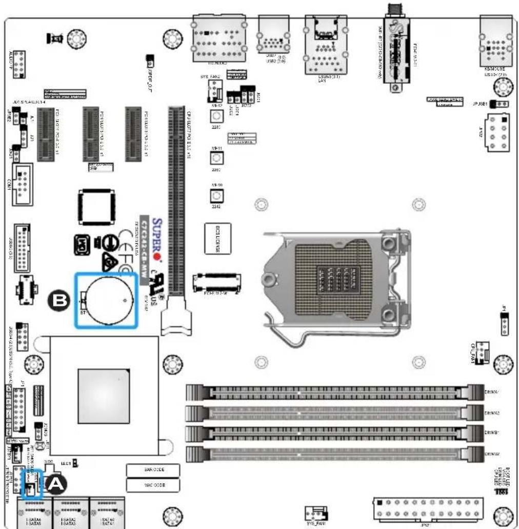
Battery Connector
BT1 is a two-pin connector for an external CMOS battery. Refer to Chapter 3 for battery installation instructions. This connector is also used to clear the CMOS. To clear the CMOS, remove the battery, short pins 1 and 2 then install the battery.
A. DOM PWR
B. Battery Connector
Standby Power Header (JSTBY1)
The standby power header is located at JSTBY1 on the motherboard. Refer to the table on the right for pin definitions.
| Standby Power Pin Definitions | |
| Pin# | Definition |
| 1 +5V | Standby |
| 2 Ground | |
| 3 Wake-up | |
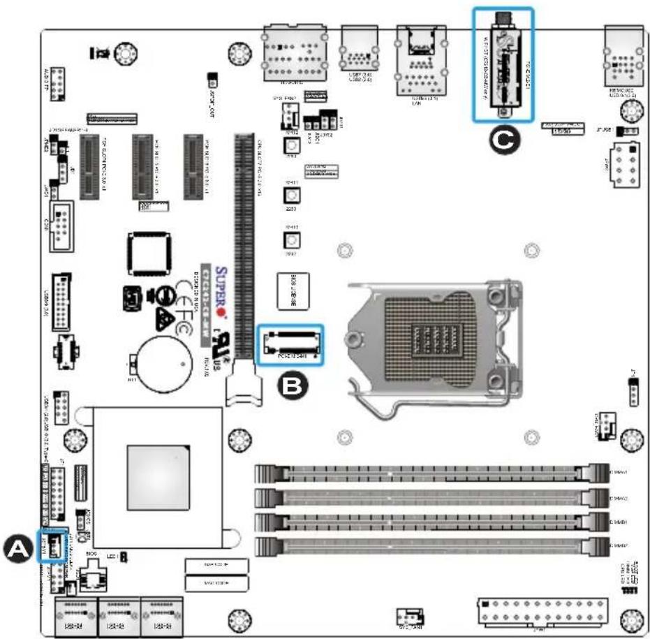
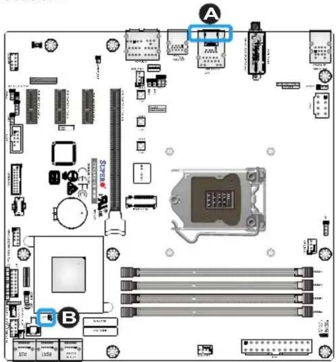
M.2 Connectors
M.2 is formerly known as Next Generation Form Factor (NGFF). The two M.2 connectors are designed for internal mounting devices and provide M-Key 2242/2260/2280 (PCI-E M.2-M1) for native PCI-E SSD support and E-Key (PCI-E M.2-E1) dedicated support for WiFi and bluetooth devices with the ultimate performance capability in a PCI-E 3.0 interface.
A. Standby Power Header
B. PCI-E M.2-M1
C. PCI-E M.2-E1 (C7C242-CB-MW only)
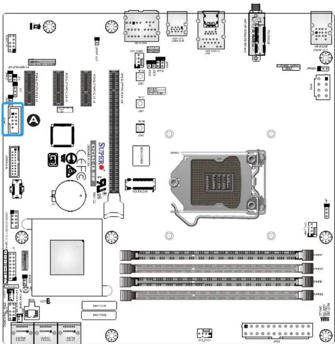
Front Panel Audio Header (AUDIO FP)
A 10-pin Audio header is supported on the motherboard. This header allows you to connect the motherboard to a front panel audio control panel, if needed. Connect an audio cable to the audio header to use this feature (not supplied). Refer to the table on the right for pin definitions.
| 10-pin Audio Header Pin Definitions | |
| Pin# | Signal |
| 1 | Microphone_Left |
| 2 | Audio_Ground |
| 3 | Microphone_Right |
| 4 | Audio_Detect |
| 5 | Line_2_Right |
| 6 | Ground |
| 7 | Jack_Detect |
| 8 | Key |
| 9 | Line_2_Left |
| 10 | Ground |
TPM/Port 80 Header
A Trusted Platform Module/Port 80 header is located at JTPM1 to provide TPM support and Port 80 connection. Use this header to enhance system performance and data security. Refer to the table on the right for pin definitions.
| TPM/Port 80 HeaderPin Definitions | |||
| Pin# | Definition | Pin# | Definition |
| 1 +3.3V | 2 SPI_CS# | ||
| 3 RESET# | 4 SPI_MISO | ||
| 5 SPI_CLK | 6 GND | ||
| 7 SPI_MOSI | 8 | ||
| 9 +3.3V | Stdby 10 SPI_IRQ# | ||
A. AUDIO FP
B. TPM/Port 80 Header
2-9 Jumper Settings
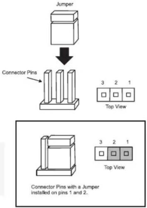
Explanation of Jumpers
To modify the operation of the motherboard, jumpers can be used to choose between optional settings. Jumpers create shorts between two pins to change the function of the connector. Pin 1 is identified with a square solder pad on the printed circuit board.

Note: On two-pin jumpers, "Closed" means the jumper is on, and "Open" means the jumper is off the pins.
flowchart
graph TD
    A["Jumper"] --> B["Connector Pins"]
    B --> C["3 2 1 Top View"]
    B --> D["3 2 1 Top View"]
    style A fill:#f9f,stroke:#333
    style B fill:#ccf,stroke:#333
    style C fill:#cfc,stroke:#333
    style D fill:#fcc,stroke:#333
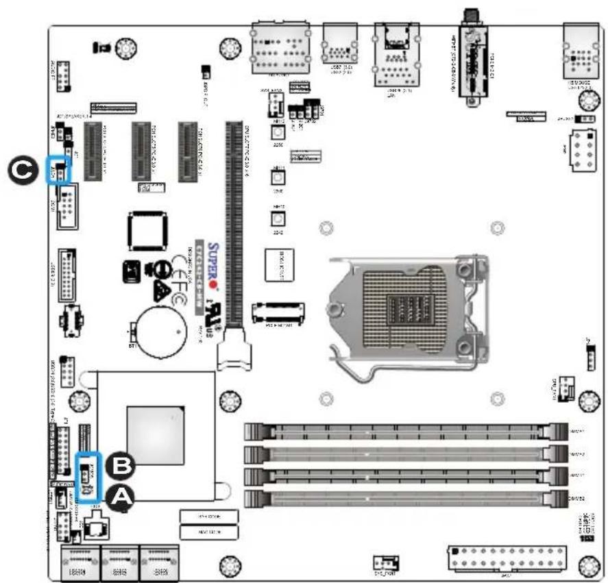
JBT1 and JCMOS
JBT1 is used to clear the saved system setup configuration stored in the CMOS chip. To clear the contents of the CMOS using JBT1, short the two pads of JBT1 with a metallic conductor such as a flathead screwdriver. JCMOS works similarly to JBT1. Close pins 2 and 3 of JCMOS to clear CMOS. This will erase all user settings and revert everything to their factory defaults.
Watch Dog Timer Enable/Disable
Watch Dog (JWD1) is a system monitor that can reboot the system when a software application hangs. Close pins 1 and 2 to reset the system if an application hangs. Close pins 2 and 3 to generate a non-maskable interrupt signal for the application that hangs. Refer to the table on the right for jumper settings.
| Watch DogJumper Settings | |
| Jumper Setting | Definition |
| Pins 1-2 Reset (default) | |
| Pins 2-3 NMI | |
| Open Disabled | |
A. JBT1
B. JCMOS
C. JWD1
Manufacturing Mode
Close pins 2 and 3 of JPME2 to bypass SPI flash security and force the system to operate in Manufacturing Mode, allowing the user to flash the system firmware from a host server for system setting modifications. Refer to the table on the right for jumper settings.
| Manufacture ModeJumper Settings | |
| Pin# | Definition |
| 1-2 | Normal (Default) |
| 2-3 | Manufacture Mode |
A. Manufacturing Mode
2-10 LED Indicators
LAN LEDs
One LAN port is located on the I/O back panel of the motherboard. This Ethernet LAN port has two LEDs (Light Emitting Diode). The yellow LED indicates activity, while the Link LED may be green, amber, or off to indicate the speed of the connections. Refer to the tables on the right for more information.
| GLAN Activity IndicatorLED Settings | ||
| Color | Status | Definition |
| Yellow Flashing Active | ||

| GLAN Link IndicatorLED Settings | |
| LED Color | Definition |
| Off No Connection | |
| Green 100Mbps/10Mbps | |
| Amber 1 Gbps | |
Onboard Power LED (LED1)
An onboard power LED is located at LED1 on the motherboard. When LED1 is on, the AC power cable is connected. Make sure to disconnect the power cable before removing or installing any component. See the layout below for the LED location.
| Onboard PWR LED IndicatorLED Status | |
| Status | Definition |
| Off System | Off |
| On System | on, orSystem off and PWRCable Connected |
A. LAN LEDs
B. Onboard Power LED
2-11 Hard Drive Connections
SATA Connections (I-SATA0\~I-SATA5)
Six Serial ATA (SATA) 3.0 connectors (I-SATA 0\~5) are supported by the Intel C242 chip. Refer to the table below for pin definitions.
| SATA 2.0/3.0 Connectors Pin Definitions |
| Pin# Signal |
| 1 Ground |
| 2 SATA_TXP |
| 3 SATA_TXN |
| 4 Ground |
| 5 SATA_RXN |
| 6 SATA_RXP |
| 7 Ground |
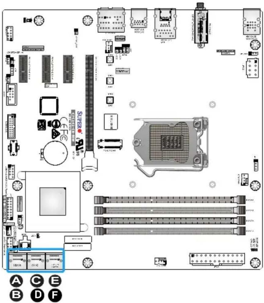
A. I-SATA4
B. I-SATA5
C. I-SATA2
D. I-SATA3
E. I-SATAO
F. I-SATA1
Chapter 3
Troubleshooting
3-1 Troubleshooting Procedures
Use the following procedures to troubleshoot your system. If you have followed all of the procedures below and still need assistance, refer to the 'Technical Support Procedures' and/or 'Returning Merchandise for Service' section(s) in this chapter. Always disconnect the AC power cord before adding, changing or installing any hardware components.
Before Power On
- Make sure that the Standby PWR LED is not on. (Note: If it is on, the onboard power is on. Be sure to unplug the power cable before installing or removing the components.)
- Make sure that there are no short circuits between the motherboard and chassis.
- Disconnect all ribbon/wire cables from the motherboard, including those for the keyboard and mouse. Also, be sure to remove all add-on cards.
- Install a CPU and heatsink (be sure that it is fully seated) and then connect the chassis speaker and the power LED to the motherboard. Check all jumper settings as well.
No Power
- Make sure that there are no short circuits between the motherboard and chassis.
- Make sure that all jumpers are set to their default positions.
- Check if the 115V/230V switch on the power supply is properly set.
-
Turn the power switch on and off to test the system.
-
The battery on your motherboard may be old. Check to make sure that it still supplies \~3VDC. If it does not, replace it with a new one.
No Video
- If the power is on, but you have no video--in this case, you will need to remove all the add-on cards and cables first.
- Use the speaker to determine if any beep codes exist. (Refer to Appendix A for details on beep codes.)
- Remove all memory modules and turn on the system. (If the alarm is on, check the specifications of memory modules, reset the memory or try a different one.)
Memory Errors
- Make sure that the DIMM modules are properly installed and fully seated in the slots.
- You should be using unbuffered Non-ECC DDR4 (up to 2666MHz) memory recommended by the manufacturer. Also, it is recommended that you use the memory modules of the same type and speed for all DIMMs in the system. Do not use memory modules of different sizes, different speeds and different types on the same motherboard.
- Check for bad DIMM modules or slots by swapping modules between slots to see if you can locate the faulty ones.
- Check the switch of 115V/230V power supply.
When the System is Losing the Setup Configuration
- Please be sure to use a high quality power supply. A poor quality power supply may cause the system to lose CMOS setup information. Refer to Section 1-7 for details on recommended power supplies.
-
The battery on your motherboard may be old. Check to verify that it still supplies \~3VDC. If it does not, replace it with a new one.
-
If the above steps do not fix the Setup Configuration problem, contact your vendor for repairs.
3-2 Technical Support Procedures
Before contacting Technical Support, please make sure that you have followed all the steps listed below. Also, note that as a motherboard manufacturer, Supermicro does not sell directly to end users, so it is best to first check with your distributor or reseller for troubleshooting services. They should know of any possible problem(s) with the specific system configuration that was sold to you.
- Please go through the 'Troubleshooting Procedures' and 'Frequently Asked Questions' (FAQ) sections in this chapter or see the FAQs on our website (http://www.supermicro.com/support/faqs/) before contacting Technical Support.
- BIOS upgrades can be downloaded from our website at (http://www.supermicro.com/support/bios/).

Note: Not all BIOS can be flashed. Some cannot be flashed; it depends on the boot block code of the BIOS.
-
If you've followed the instructions above to troubleshoot your system, and still cannot resolve the problem, then contact Supermicro's technical support and provide them with the following information:
-
Motherboard model and PCB revision number
- BIOS release date/version (this can be seen on the initial display when your system first boots up)
• System configuration -
An example of a Technical Support form is on our website at (http://www.supermicro.com/support/contact.cfm).
-
Distributors: For immediate assistance, please have your account number ready when placing a call to our technical support department. We can be reached by e-mail at support@supermicro.com, by phone at: (408) 503-8000, option 2, or by fax at (408) 503-8019.
3-3 Frequently Asked Questions
Question: What type of memory does my motherboard support?
Answer: The C7C242-CB-M/-MW supports up to 64GB of unbuffered Non-ECC U-DIMM DDR4. See Section 2-4 for details on installing memory.
Question: How do I update my BIOS?
Answer: It is recommended that you do not upgrade your BIOS if you are not experiencing any problems with your system. Updated BIOS files are located on our website at http://www.supermicro.com. Please check our BIOS warning message and the information on how to update your BIOS on our website. Select your motherboard model and download the BIOS file to your computer. Also, check the current BIOS revision to make sure that it is newer than your BIOS before downloading. To update your BIOS under the UEFI shell, please unzip the BIOS file onto a USB device formatted with the FAT/FAT32 file system. When the UEFI shell prompt appears, type fs# to change the device directory path. Go to the directory that contains the BIOS package you extracted earlier. Enter flash.nsh BIOSname#.### at the prompt to start the BIOS update process. Reboot the system when you see the message that BIOS update has completed.
! Attention! Do not shut down or reset the system while updating the BIOS to prevent possible system boot failure!
Question: I think my BIOS is corrupted. How can I recover my BIOS?
Answer: Please see Appendix C - BIOS Recovery for detailed instructions.
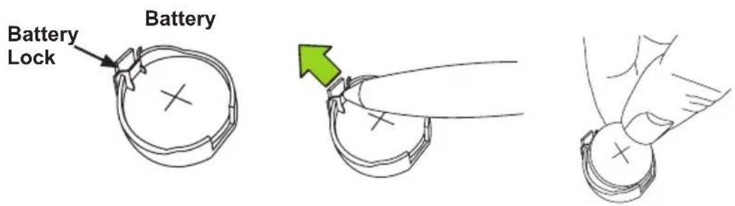
3-4 Battery Removal and Installation
Battery Removal
To remove the onboard battery, follow the steps below:
- Power off your system and unplug your power cable.
- Locate the onboard battery as shown below.
- Using a tool such as a pen or a small screwdriver, push the battery lock outwards to unlock it. Once unlocked, the battery will pop out from the holder.
- Remove the battery.
Proper Battery Disposal
! Attention! Please handle used batteries carefully. Do not damage the battery in any way; a damaged battery may release hazardous materials into the environment. Do not discard a used battery in the garbage or a public landfill. Please comply with the regulations set up by your local hazardous waste management agency to dispose of your used battery properly.
Battery Installation
- To install an onboard battery, follow the steps 1 and 2 above and continue below:
- Identify the battery's polarity. The positive (+) side should be facing up.
- Insert the battery into the battery holder and push it down until you hear a click to ensure that the battery is securely locked.
! Attention! When replacing a battery, be sure to only replace it with the same type.

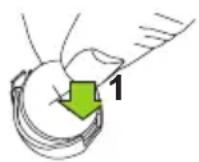
2
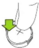
Press down until you hear a click.
3-5 Returning Motherboard for Service
A receipt or copy of your invoice marked with the date of purchase is required before any warranty service will be rendered. You can obtain service by calling your vendor for a Returned Merchandise Authorization (RMA) number. For faster service, you may also obtain RMA authorizations online (http://www.supermicro.com/RmaForm/). When you return the motherboard to the manufacturer, the RMA number should be prominently displayed on the outside of the shipping carton, and mailed prepaid or hand-carried. Shipping and handling charges will be applied for all orders that must be mailed when service is complete.
This warranty only covers normal consumer use and does not cover damages incurred in shipping or from failure due to the alteration, misuse, abuse or improper maintenance of products.
During the warranty period, contact your distributor first for any product problems.
Chapter 4
UEFI BIOS
4-1 Introduction
This chapter describes the AMI BIOS Setup utility for the C7C242-CB-M/-MW. The ROM BIOS is stored in a Flash EEPROM and can be easily updated. This chapter describes the basic navigation of the AMI BIOS Setup utility setup screens.

Note: For AMI BIOS Recovery, please refer to the UEFI BIOS Recovery Instructions in Appendix C.
Starting BIOS GUI Setup Utility
To enter the AMI BIOS Setup utility screens, press the
![Antio Setup Utility - Copyright (C) 2018 American Megatrends, Inc. Main Advanced Event Logs Security Boot Hardware Monitor Save & Exit System Date [Fri 01/09/2009] System Time [07:39:38] Supermicro C7C242-CB-MW BIOS Version T20180725152845 Build Date 07/25/2018 Memory Information Total Memory B192 MB Set the Date. Use Tab to switch between Date elements. Default Ranges: Year: 2005-2099 Months: 1-12 Days: dependent on month +: Select Screen ↑↓: Select Item Enter: Select +/-: Change Opt. F1: General Help F2: Previous Values F3: Optimized Defaults F4: Save & Exit ESC: Exit Version 2.20.1271. Copyright (C) 2018 American Megatrends, Inc.](/content/2026/05/981949/images/93383704fa023d1a8bdc34660721369210d7b5dfe8f7c5568cac6b7bfd38df03.jpg)
Each BIOS menu option is described in this manual. The Main BIOS Setup screen has two main areas. The bottom-left area is the Configuration area, and the top area is for Menu Navigation. Icons that do not respond when the mouse pointer is hovering on top are not configurable.
The AMI BIOS Setup utility uses key strokes for navigation. Use the keyboard's arrow keys to navigate up, down, left, and right throughout the menus. Use the
You may press the
The keyboard's Escape key
How To Change the Configuration Data
The configuration data that determines the system parameters may be changed by entering the AMI BIOS GUI Setup utility. This Setup utility can be accessed by pressing at the appropriate time during system boot.

Note: For the purposes of this manual, options that are printed in Bold are default settings.
Warning! Do not upgrade the BIOS unless your system has a BIOS-related issue. Flashing the wrong BIOS can cause irreparable damage to the system. In no event shall Supermicro be liable for direct, indirect, special, incidental, or consequential damages arising from a BIOS update. If you have to update the BIOS, do not shut down or reset the system while the BIOS is updating. This is to avoid possible boot failure.
4-2 Main
When you first enter the AMI BIOS Setup utility, you will enter the Main setup screen. You can always return to the Main setup screen by selecting the Main tab on the top of the screen. The Main BIOS Setup screen is shown below.
![Aptio Setup Utility - Copyright (C) 2018 American Megatrends, Inc. Main Advanced Event Logs Security Boot Hardware Monitor Save & Exit System Date [Fri 01/09/2009] System Time [07:39:38] Supermicro C7C242-CB-MW BIOS Version T20160725152845 Build Date 07/25/2018 Memory Information Total Memory 8192 MB Set the Date. Use Tab to switch between Date elements. Default Ranges: Year: 2005-2099 Months: 1-12 Days: dependent on month +: Select Screen ↑↓: Select Item Enter: Select +/-: Change Opt. F1: General Help F2: Previous Values F3: Optimized Defaults F4: Save & Exit ESC: Exit Version 8.20.1271. Copyright (C) 2018 American Megatrends, Inc.](/content/2026/05/981949/images/f7025122fe4a428418f167f1ed99f3c94aeac5e83d83d21fa488ef502cf5b5b1.jpg)
System Date/System Time
Use this option to change the system time and date. Highlight System Time or System Date using the arrow keys. Enter new values through the keyboard. Press the

Note: The time is in the 24-hour format. For example, 5:30 P.M. appears as 17:30:00.
BIOS Version
Build Date
Total Memory
4-3 Advanced
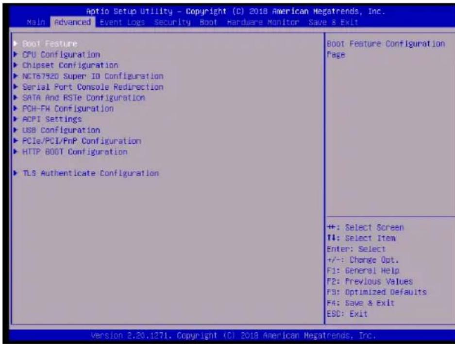
▶ Boot Feature
Fast Boot
This feature enables the system to boot with a minimal set of required devices to launch. This has no effect on BBS boot options. The options are Disabled and Enabled.
Quiet Boot
Use this feature to select the screen display between the POST messages and the OEM logo upon bootup. Uncheck the box to display the POST messages. Check the box to display the OEM logo instead of the normal POST messages. The default is Checked.
Bootup Num-Lock
Use this feature to set the Power-on state for the
Option ROM Messages
This feature sets the display mode for Option ROM. The options are Force BIOS and Keep Current.
Wait for "F1" If Error
Use this feature to force the system to wait until the "F1" key is pressed if an error occurs. The options are Disabled and Enabled.
Re-try Boot
If this feature is enabled, the BIOS will automatically reboot the system from a specified boot device after its initial boot failure. The options are Disabled, Legacy Boot, and EFI Boot.
Watch Dog Function
If enabled, the Watch Dog Timer will allow the system to reset or generate NMI based on jumper settings when it is expired for more than 5 minutes. The options are Disabled and Enabled.
AC Loss Policy Depend on
Use this feature to set the power state after a power outage. Select Stay Off for the system power to remain off after a power loss. Select Power On for the system power to be turned on after a power loss. Select Last State to allow the system to resume its last power state before a power loss. The options are Stay Off, Power On, and Last State.
Power Button Function
This feature controls how the system shuts down when the power button is pressed. Select 4 Seconds Override for the user to power off the system after pressing and holding the power button for four seconds or longer. Select Instant Off to instantly power off the system as soon as the user presses the power button. The options are Instant Off and 4 Seconds Override.
EuP Support
This feature enables EuP support. The options are Disabled and Enabled.
DeepSx Power Policies
This feature enables DeepSx Mode configurations. The options are Disabled and Enabled in S4-S5.
▶CPU Configuration
CPU Flex Ratio Override
This feature enables CPU Flex Ratio override programming. The options are Disabled and Enabled.
Hardware Prefetcher (Available when supported by the CPU)
If set to Enabled, the hardware prefetcher will prefetch streams of data and instructions from the main memory to the L2 cache to improve CPU performance. The options are Disabled and Enabled.
Adjacent Cache Line Prefetch (Available when supported by the CPU)
Select Enabled for the CPU to prefetch both cache lines for 128 bytes as comprised. Select Disabled for the CPU to prefetch both cache lines for 64 bytes. The options are Disabled and Enabled.
Intel® (VMX) Virtualization Technology (Available when supported by the CPU)
Select Enabled to use the Intel Virtualization Technology to allow one platform to run multiple operating systems and applications in independent partitions, creating multiple "virtual" systems in one physical computer. The options are Disabled and Enabled.

Note: If there is any change to this setting, you will need to power off and restart the system for the change to take effect. Please refer to Intel's web site for detailed information.
Active Processor Cores
Enables selection of the number of the processor's core to activate. (Please refer to Intel's web site for more information.) The options are All, 1, 2, and 3.
Hyper-Threading (Available when supported by the OS and the CPU)
Select Enabled to enable Hyper-Threading support to increase CPU performance. The options are Disabled and Enabled.
BIST
Select Enabled to activate the Built-In Self Test (BIST) on reset. The options are Disabled and Enabled.
AES
This feature enables the processor's Advanced Encryption Standard support. The options are Disabled and Enabled.
Boot Performance Mode
This feature enables the selection of the default CPU performance during system boot. The options are Max Non-Turbo Performance, Max Battery, and Turbo Performance.
Intel® SpeedStep™
Intel SpeedStep Technology allows the system to automatically adjust processor voltage and core frequency in an effort to reduce power consumption and heat dissipation. Please refer to Intel's website for detailed information. The options are Disabled and Enabled.
Intel® Speed Shift Technology
This feature enables Intel Speed Shift Technology support, which allows for hardware controlled P-states. The options are Disabled and Enabled.
Turbo Mode
When Intel Speed Step or Speed Shift is enabled, this feature enables the processor Turbo Mode. The options are Disabled and Enabled.
C states
C-State architecture, a processor power management platform developed by Intel, can further reduce power consumption from the basic C1 (Halt State) state that blocks clock cycles to the CPU. Select Enabled for CPU C-State support. The options are Disabled and Enabled. If this feature is set to Enabled, the following features will display:
Enhanced C-states
This feature enables Enhanced C1 Power State to boost system performance. The options are Disabled and Enabled.
C-State Auto Demotion
When this feature is enabled, the CPU will conditionally demote C State based on un-cored auto-demote information. The options are Disabled, C1, C3, and C1 and C3.
C-State Un-demotion
When this feature is enabled, the CPU will conditionally undemote from demoted C3 or C1. The options are Disabled, C1, C3, and C1 and C3.
Package C-State Demotion
This feature enables the Package C-State demotion. The options are Disabled and Enabled.
Package C-State Un-demotion
When this feature is enabled, the CPU will conditionally undemote from demoted Package C-State Un-Demotion. The options are Disabled and Enabled.
CState Pre-Wake
Use this feature to enable the C-State pre wake. The options are Disabled and Enabled.
Package C-State limit
Select Auto for the AMI BIOS to automatically set the limit on the C-State package register. The options are C0/C1, C2, C3, C6, C7, C7S, C8, C9, C10, Cpu Default, and Auto.
▶ Chipset Configuration
▶System Agent (SA) Configuration
▶Memory Configuration
Maximum Memory Frequency
This feature selects the type/speed of the memory installed. The options are 1333, 1600, 1867, 2133, 2400, 2667, 2933, and 3200. All values are in MHz. Default speed is auto detected.
ECC Support
This feature enables memory ECC support. The options are Disabled and Enabled.
Max TOLUD
This feature controls the maximum TOLUD value. The options are Dynamic, and 1 GB\~3.5 GB (in 0.25 GB increments).
Memory Scrambler
This feature enables memory scrambler support for memory error correction. The settings are Disabled and Enabled.
Fast Boot
This feature enables fast path through MRC. The settings are Disabled and Enabled.
REFRESH\_2X\_MODE
This feature enables 2X Refresh mode. The options are Disabled, 1- Enabled for WARM or HOT, and 2- Enabled HOT only.
▶DMI/OPI Configuration
DMI Link ASPM Control
This feature enables Active State Power Management (ASPM) for the SA side of the DMI Link. The options are Disabled, L0s, L1, and L0sL1.
DMI Extended Sync Control
This feature enables DMI Extended Synchronization control. The options are Disabled and Enabled.
DMI De-emphasis Control
This feature configures DMI De-emphasis. The options are -6 dB and -3.5 dB.
▶PEG Port Configuration
PEG 0:1:0
Enable Root Port
Select Enable to activate the Root Port. The options are Disabled, Enabled, and Auto.
Max Link Speed
Select Auto, Gen1, Gen2, or Gen3 to set the PEG Max Link Speed.
Max Link Width
Select Auto, Force X1, Force X2, Force X4, or Force X8 to set the PEG Max Link Width.
ASPM
This feature configures ASPM support for the PEG. The options are Disabled, Auto, ASPM L0s, ASPM L1, and ASPM L0sL1.
De-emphasis Control
This feature configures PEG De-emphasis. The options are -6 dB and -3.5 dB.
PEG0 Slot Power Limit Value
Enter a value for the upper power limit (in watts) supplied to the PEG slot. The default is 75.
PEG0 Slot Power Limit Scale
This feature controls the PEG slot power limit scale. The options are 1.0x, 0.1x, 0.01x, and 0.001x.
PEG0 Physical Slot Number
Enter a value for the physical slot number attached to this PEG port. The default is 1.
PEG0 Max Payload size
This feature controls the max payload size for this port. The options are Auto, 128, and 256 TLP.
PEG 0:1:1\~0:1:2 Enable Root Port
Select Enable to activate the Root Port. The options are Disabled, Enabled, and Auto.
Max Link Speed
Select Auto, Gen1, Gen2, or Gen3 to set the PEG Max Link Speed.
PEG1/2 Slot Power Limit Value
Enter a value for the upper power limit (in watts) supplied to the PEG slot. The default is 75.
PEG1/2 Slot Power Limit Scale
This feature controls the PEG slot power limit scale. The options are 1.0x, 0.1x, 0.01x, and 0.001x.
PEG1/2 Physical Slot Number
Enter a value for the physical slot number attached to this PEG port. The default for PEG1 is 2 and for PEG2 is 3.
PEG1/2 Max Payload size
This feature controls the max payload size for this port. The options are Auto, 128, and 256 TLP.
PEG 0:6:0
Enable Root Port
Select Enable to activate the Root Port. The options are Disabled, Enabled, and Auto.
Max Link Speed
Select Auto, Gen1, Gen2, or Gen3 to set the PEG Max Link Speed.
Program PCIe ASPM after OpROM
This feature enables PCIe ASPM programming after OpROM. The options are Disabled and Enabled.
VT-d
This feature enables VT-d. The options are Disabled and Enabled.
GNA Device
This feature enables the SA GNA device. The options are Disabled and Enabled.
X2APIC Opt Out
This feature enables X2APIC Opt Out. The options are Disabled and Enabled.
▶ PCH-IO Configuration
▶PCI Express Configuration
DMI Link ASPM Control
This feature enables Active State Power Management (ASPM) for the DMI Link. The options are Disabled, L0s, L1, L0sL1, and Auto.
Peer Memory Write Enable
This feature enables Peer Memory Writing. The options are Disabled and Enabled.
▶PCI Express Root Port 1\~24
ASPM
This feature controls the ASPM configuration for the PCI Express Root Port. The default is Auto.
L1 Substates
This feature controls the L1 Substate for the PCI Express Root Port. The default is L1.1 & L1.2.
PCIe Speed
This feature controls the PCIe speed configuration. The default is Auto.
Port 61h Bit-4 Emulation
This feature enables emulation of Port 61h Bit-4 in SMM. The options are Disabled and Enabled.
PCIe PLL SSC
This feature enables PCIe PLL SSC. The options are Disabled and Enabled.
▶NCT6792D Super IO Configuration
SuperIO Chip NCT6792D
▶Serial Port 1 Configuration
Serial Port
This feature will Enable or Disable Serial Port 1 (COM1). Click to check the box to enable Serial Port 1. The default is Enabled.
Device Settings
This feature displays the current IRQ setting for Serial Port 1 (COM1).
Change Settings
This feature configures the IRQ setting for Serial Port 1 (COM1). The default is Auto.
▶Serial Port Console Redirection
COM 1
Console Redirection
Select Enabled to enable COM Port 1 Console Redirection, which will allow a client machine to be connected to a host machine at a remote site for networking. The options are Disabled and Enabled.
*If the item above is set to Enabled, the following features will become available for configuration:
▶ Console Redirection Settings
Terminal Type
This feature allows the user to select the target terminal emulation type for Console Redirection. Select VT100 to use the ASCII Character set. Select VT100+ to add color and function key support. Select ANSI to use the Extended ASCII Character Set. Select VT-UTF8 to use UTF8 encoding to map Unicode characters into one or more bytes. The options are ANSI, VT100, VT100+, and VT-UTF8.
Bits per second
Use this feature to set the transmission speed for a serial port used in Console Redirection. Make sure that the same speed is used in the host computer and the client computer. A lower transmission speed may be required for long and busy lines. The options are 9600, 19200, 38400, 57600, and 115200 (bits per second).
Data Bits
Use this feature to set the data transmission size for Console Redirection. The options are 7 (Bits) and 8 (Bits).
Parity
A parity bit can be sent along with regular data bits to detect data transmission errors. Select Even if the parity bit is set to 0, and the number of 1's in data bits is even. Select Odd if the parity bit is set to 0, and the number of 1's in data bits is odd. Select None if you do not want to send a parity bit with your data bits in transmission. Select Mark to add a mark as a parity bit to be sent along with the data bits. Select Space to add a Space as a parity bit to be sent with your data bits. The options are None, Even, Odd, Mark, and Space.
Stop Bits
A stop bit indicates the end of a serial data packet. Select 1 Stop Bit for standard serial data communication. Select 2 Stop Bits if slower devices are used. The options are 1 and 2.
Flow Control
Use this feature to set the flow control for Console Redirection to prevent data loss caused by buffer overflow. Send a "Stop" signal to stop sending data when the receiving buffer is full. Send a "Start" signal to start sending data when the receiving buffer is empty. The options are None and Hardware RTS/CTS.
VT-UTF8 Combo Key Support
Select Enabled to enable VT-UTF8 Combination Key support for ANSI/VT100 terminals. The options are Disabled or Enabled.
Recorder Mode
Select Enabled to capture the data displayed on a terminal and send it as text messages to a remote server. The options are Disabled and Enabled.
Resolution 100x31
Select Enabled for extended-terminal resolution support. The options are Disabled and Enabled.
Legacy OS Redirection Resolution
Use this feature to select the number of rows and columns used in Console Redirection for legacy OS support. The options are 80x24 and 80x25.
Putty KeyPad
This feature selects Function Keys and KeyPad settings for Putty, which is a terminal emulator designed for the Windows OS. The options are VT100, LINUX, XTERMR6, SCO, ESCN, and VT400.
Redirection After BIOS POST
Use this feature to enable or disable legacy Console Redirection after BIOS POST. When the option-Bootloader is selected, legacy Console Redirection is disabled before booting the OS. When the option Always Enable is selected, legacy Console Redirection remains enabled upon OS bootup. The options are Always Enable and Bootloader.
▶Console Redirection Settings
Redirection COM Port
This feature specifies which COM port to display Legacy OS and Legacy OpROM redirection messages to. The default is COM1.
Legacy OS Redirection Resolution
This feature controls the number of rows and columns supported by Legacy OS redirection. The options are 80x24 and 80x25.
Redirection After POST
When this feature is set to Always Enabled, Legacy Console redirection will be enabled for legacy operating systems. The default is Always Enabled.
Serial Port for Out-of-Band Management/Windows Emergency Management Services (EMS)
The submenu allows the user to configure Console Redirection settings to support Out-of-Band Serial Port management.
Console Redirection
Select Enabled to use a COM port selected by the user for EMS Console Redirection. The options are Disabled and Enabled.
*If the item above is set to Enabled, the following features will become available for user configuration:
▶Console Redirection Settings
Out-of-Band Mgmt Port
The feature selects a serial port in a client server to be used by the Windows Emergency Management Services (EMS) to communicate with a remote host server. The options are dependent on the available COM ports.
Terminal Type
Use this feature to select the target terminal emulation type for Console Redirection. Select VT100 to use the ASCII character set. Select VT100+ to add color and function key support. Select ANSI to use the extended ASCII character set. Select VT-UTF8 to use UTF8 encoding to map Unicode characters into one or more bytes. The options are ANSI, VT100, VT100+, and VT-UTF8.
Bits per second
This feature sets the transmission speed for a serial port used in Console Redirection. Make sure that the same speed is used in both host computer and the client computer. A lower transmission speed may be required for long and busy lines. The options are 9600, 19200, 57600, and 115200 (bits per second).
Flow Control
Use this feature to set the flow control for Console Redirection to prevent data loss caused by buffer overflow. Send a "Stop" signal to stop data sending when the receiving buffer is full. Send a "Start" signal to start data sending when the receiving buffer is empty. The options are None, Hardware RTS/CTS, and Software Xon/Xoff.
The setting for each these features is displayed:
Data Bits, Parity, Stop Bits
▶SATA and RSTe Configuration
SATA Controller(s)
This feature enables SATA device(s). The options are Disabled and Enabled.
SATA Mode Selection
This feature controls the SATA mode. The options are AHCI and Intel RST With Intel Optane System Acceleration.
SATA Frozen
This feature enables SATA freeze lock security support. The options are Disabled and Enabled.
Aggressive LPM Support
This feature enables the PCH to aggressively enter link power state. The options are Disabled and Enabled.
Storage Option ROM/UEFI Driver
This feature controls the execution of UEFI and Legacy Storage OpROM. The options are Do not launch, UEFI, and Legacy.
Serial ATA Port 0\~5 Hot Plug
This feature designates the port specified for hot plugging. Set this feature to Enabled for hot-plugging support, which will allow the user to replace a SATA disk drive without shutting down the system. The options are Disabled and Enabled.
Spin Up Device
When this feature is disabled, all drives will spin up at boot. When this option is enabled, it will perform Staggered Spin Up on any drive this option is activated. The settings are Disabled and Enabled.
SATA Device Type
Use this feature to identify the type of HDD that is connected to the SATA port. The options are Hard Disk Drive and Solid State Drive.
▶ACPI Settings
WHEA Support
Enable this feature to support the Windows Hardware Error Architecture (WHEA) platform and provide a common infrastructure for the system to handle hardware errors within the Windows OS environment in order to reduce system crashes and enhance system recovery and health monitoring. The options are Disabled and Enabled.
High Precision Event Timer
Select Enabled to activate the High Precision Event Timer (HPET) that produces periodic interrupts at a much higher frequency than a Real-time Clock (RTC) does in synchronizing multimedia streams, providing smooth playback and educing the dependency on other timestamp calculation devices, such as an x86 RDTSC Instruction embedded in the CPU. The High Performance Event Timer is used to replace the 8254 Programmable Interval Timer. The options are Disabled and Enabled.
Native PCIE Enable
This feature enables native PCIE support. The options are Disabled and Enabled.
Native ASPM
This feature enables operating system controlled ASPM. Selecting Disabled will allow the BIOS to control ASPM. The default is Auto.
▶USB Configuration
The following information is displayed:
• USB Module Version
- USB Controllers
- USB Devices
Legacy USB Support
Select Enabled to support legacy USB devices. Select Auto to disable legacy support when legacy USB devices are not present. If Disable is selected, legacy USB devices will not be supported. The options are Disabled, Enabled, and Auto.
XHCI Hand-Off
This feature is a work-around solution for operating systems that do not support XHCI (Extensible Host Controller Interface) hand-off. The XHCI ownership change should be claimed by the XHCI driver. The settings are Disabled and Enabled.
USB Mass Storage Driver Support
This feature enables USB mass storage driver support. The options are Disabled and Enabled.
Port 60/64 Emulation
This feature enables port 60/64h emulation support, which is used to complete USB keyboard legacy support. The options are Disabled and Enabled.
▶PCIe/PCI/PnP Configuration
PCI PERR/SERR Support
This feature enables PCI PER/SERR support. The options are Disabled and Enabled.
Above 4GB MMIO BIOS Assignment
Select Enabled for remapping of BIOS above 4GB. The options are Disabled and Enabled.
NVMe Firmware Source
This feature controls the NVMe firmware source, between AMI native support or vendor defined firmware. The default is Vendor Defined Firmware.
PCH SLOT4 PCI-E 3.0 X1 OPROM PCH SLOT5 PCI-E 3.0 X1 OPROM PCH SLOT6 PCI-E 3.0 X1 OPROM CPU SLOT7 PCI-E 3.0 X16 OPROM
Select Disabled to deactivate the selected slot, Legacy to activate the slot in legacy mode and EFI to activate the slot in EFI mode. The options are Disabled, Legacy, and EFI.
Onboard LAN Option ROM type
Use this feature to select the type of option ROM installed. The options are EFI and Legacy.
Network Stack
Select Enabled to enable PXE (Preboot Execution Environment) or UEFI (Unified Extensible Firmware Interface) for network stack support. The options are Disabled and Enabled.
*If this feature is enabled, the two features below are available.
Ipv4 PXE Support
Select Enabled to enable IPv4 PXE (Preboot Execution Environment) for boot support. If this feature is set to Disabled, IPv4 PXE boot option will not be supported. The options are Disabled and Enabled.
Ipv4 HTTP Support
Use this feature to enable IPv4 HTTP boot support. The options are Disabled and Enabled.
Ipv6 PXE Support
Select Enabled to enable IPv6 PXE (Preboot Execution Environment) for boot support. If this feature is set to Disabled, IPv6 PXE boot option will not be supported. The options are Disabled and Enabled.
Ipv6 HTTP Support
Use this feature to enable IPv6 HTTP boot support. The options are Disabled and Enabled.
IPSEC Certificate
This feature enables IPSEC certificate for Ikev. The options are Disabled and Enabled.
PXE boot wait time
Enter a value for the wait time (in seconds) to press the ESC key to abort the PXE boot. The default is 0.
Media detect count
Enter a value for the number of times the presence of media will be checked. The default is 1.
▶ Trusted Computing

Note: This submenu will only appear when a TPM device is installed.
Security Device Support
This feature enables BIOS support for security devices. The options are Disabled and Enabled.
TPM State
This feature enables the TPM device "On" state. Changing this setting will reboot the system. The options are Disabled and Enabled.
Pending operation
This feature schedules an operation for the security device. Changing this setting will reboot the system. The options are None and TPM Clear.
Device Select
This feature controls the TPM device type that is supported. The options are TPM 1.2, TPM 2.0, and Auto.
Current Status Information
The following information is displayed:
- TPM Enabled Status
- TPM Active Status
- TPM Owner Status
SMCI BIOS-Based TPM Provision Support
This feature enables Supermicro BIOS-based TPM provision support. Enabling this feature will not lock your TPM. The options are Disabled and Enabled.
TXT Support
This feature enables Intel Trusted Execution Technology (TXT) support. Changing this setting requires a full power cycle to take effect. The options are Disabled and Enabled.
▶HTTP BOOT Configuration
Http Boot One Time
This feature enables HTTP Boot, which is a client-server communication based application for system deployment and configuration over a network. The options are Disabled and Enabled.
Input the description
Enter a name for HTTP Boot option.
Boot URI
Enter a value for a new Boot Option to be created according to this Boot URI. The default is 0.
4-4 Event Logs
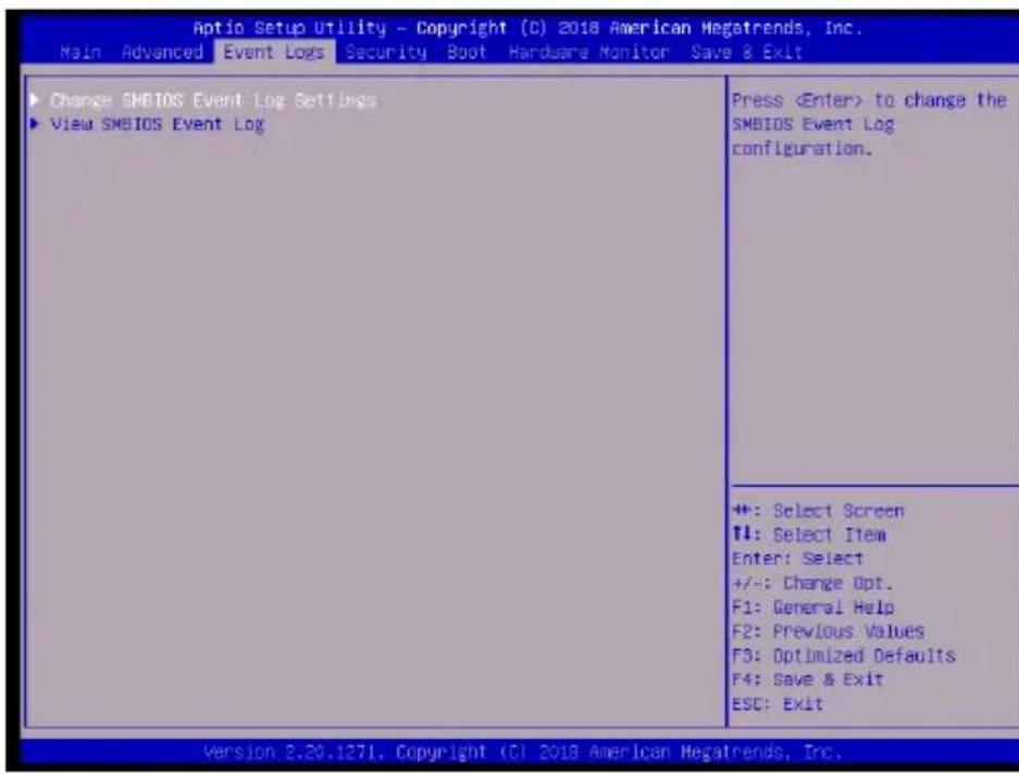
▶ Change SMBIOS Event Logs Settings
SMBIOS Event Log
This feature enables all features for SMBIOS Event Logging. The options are Disabled and Enabled.
Erase Event Log
This feature controls when Event Logs are erased. The options are No, Yes, Next reset, and Yes, Every reset.
When Log is Full
This feature controls what occurs when the SMBIOS Event Log is full. The options are Do Nothing and Erase Immediately.
Log System Boot Event
This feature enables logging of system boot events. The options are Disabled and Enabled.
MECI
The Multiple Event Count Increment (MECI) counter counts the number of occurrences that a duplicate event must happen before the MECI counter is incremented. This is a numeric value. The default value is 1.
METW
This feature is used to determine how long (in minutes) the multiple event counter should wait before generating a new event log. Enter a number between 0 and 99. The default is 60.
▶View SMBIOS Event Log
This submenu will display logged SMBIOS events.
4-5 Security
![Aptio Setup Utility - Copyright (C) 2018 American Megatrends, Inc. Main Advanced Event Logs Security Boot Hardware Monitor Save & Exit Password Description If the Administrator / User password is set, then this only limits access to Setup and is asked for when entering Setup. Please set Administrator password first in order for setting User password, if clear Administrator password, User password will be cleared as well. The password length must be in the following range: Minimum length 3 Maximum length 20 Password Check [Setup] Administrator Password ▶ Secure Boot Setup: Check password while invoking setup. Always: Check password while invoking setup as well as on each boot. ++: Select Screen ++: Select Item Enter: Select +/-: Change Opt. F1: General Help F2: Previous Values F3: Optimized Defaults F4: Save & Exit ESC: Exit Version 2.30.1271. Copyright (C) 2018 American Megatrends, Inc.](/content/2026/05/981949/images/22c78a8dddfce130b09742b5bc559e6b2b8f87bf079be751f5b7f4dc44e42ced.jpg)
Use this menu to create Administrator and User passwords. Using ONLY an Administrator password limits access to BIOS setup. Using ONLY a User password will lock unauthorized users from booting the system and/or entering BIOS setup.
4-6 Boot
![Aptio Setup Utility - Copyright (C) 2018 American Megatrends, Inc. Main Advanced Event Logs Security Boot Hardware Monitor Save & Exit Boot Configuration Setup Prompt Timeout 1 Boot mode select [DUAL] FIXED BOOT ORDER Priorities Boot Option #1 [Hard Disk] Boot Option #2 [CD/DVD] Boot Option #3 [USB Hard Disk] Boot Option #4 [USB CD/DVD] Boot Option #5 [USB Key] Boot Option #6 [USB Floppy] Boot Option #7 [USB Lan] Boot Option #8 [Network:IBA CL Slot 00FE v0113] Boot Option #9 [UEFI Hard Disk] Boot Option #10 [UEFI CD/DVD] Boot Option #11 [UEFI USB Hard Disk] Boot Option #12 [UEFI USB CD/DVD] Boot Option #13 [UEFI USB Key] Boot Option #14 [UEFI USB Floppy] Boot Option #15 [UEFI USB Lanl] Boot Option #16 [UEFI Network] Boot Option #17 [UEFI AP:UEFI: Built-In EFI Shell] Number of seconds to wait for setup activation key. 65535(0xFFFF) means indefinite waiting. +: Select Screen ++: Select Item Enter: Select +/-: Charge Opt. F1: General Help F2: Previous Values F3: Optimized Defaults F4: Save & Exit ESC: Exit Version 2.20.1271. Copyright (C) 2018 American Megatrends, Inc.](/content/2026/05/981949/images/4d1c1641c92e1335b2dc7377984a6798e999230267d5dbf9be00afa914b1ead0.jpg)
Setup Prompt Timeout
Enter a value for the number of seconds to wait for setup activation key (typically ). The default is 1.
Boot mode select
Use this feature to select the type of device to be used for system boot. The options are Legacy, UEFI, and Dual.
FIXED BOOT ORDER Priorities
The Boot Options below (depending on Boot Mode) prioritize the order of bootable devices from which the system will boot. Choose an entry from top to bottom to select devices.
Legacy Boot Option #1\~#8
The options are Hard Disk, CD/DVD, USB Hard Disk, USB CD/DVD, USB Key, USB Floppy, USB LAN, Network: IBA CL Slot 00FE v0113, and Disabled.
UEFI Boot Option #1\~#9
The options are UEFI Hard Disk, UEFI AP: UEFI: Built-in EFI Shell, UEFI CD/DVD, UEFI USB Hard Disk, UEFI USB CD/DVD, UEFI USB Key, UEFI USB Floppy, UEFI USB Lan, and UEFI Network.
DUAL Boot Option #1\~#17
The options include every option from Legacy and UEFI Boot Option (above).
UEFI Hard Disk Drive BBS Priorities
Use this feature to specify the Boot Device Priority sequence from available UEFI Hard Disk Drives.
UEFI Application Boot Priorities
Use this feature to specify the Boot Device Priority sequence from available UEFI Applications. The options are Built-in EFI Shell and Disabled.
UEFI USB Key Drive BBS Priorities
Use this feature to specify the Boot Device Priority sequence from available UEFI USB Key Drives.
NETWORK Drive BBS Priorities
Use this feature to specify the Boot Device Priority sequence from available Network Drives. The options are IBA CL Slot 00FE v0110 and Disabled.
Hard Disk Drive BBS Priorities
Use this feature to specify the Boot Device Priority sequence from available Hard Disk Drives.
USB Key Drive BBS Priorities
Use this feature to specify the Boot Device Priority sequence from available USB Key Drives. The options are SMI USB DISK 110 and Disabled.
Boot Override
Saves the specified boot override and resets the system, i.e., IBA CL Slot 00FE v0113. Select OK to activate, otherwise, click Cancel.
IBA CL Slot 00FE v0113
Launch EFI Shell from filesystem device
This feature will attempt to launch the EFI Shell application (shell.efi) from one of the available file system devices. Select OK to activate it, otherwise, click Cancel.
For the following features, select OK to initiate, otherwise, click Cancel.
Save Changes and Exit
This feature will save the changes that have been made and will exit BIOS Setup.
Discard Changes and Exit
This feature will discard the changes that have been made and will exit BIOS Setup.
Save Changes and Reset
This feature will save the changes that have been made and will reboot the system.
Discard Changes and Reset
This feature will save the changes that have been made and will reboot the system.
Save Changes
This feature will save the changes but will remain in setup mode.
Discard Changes
This feature will discard the changes but will remain in setup mode.
Default Options
Restore Defaults
This feature will load the factory-stored optimized defaults and remain in setup mode.
Save as User Defaults
This feature will save the changes as user-specified defaults and remain in setup mode.
This feature will load previously saved user-specified defaults and remain in setup mode.
4-7 Hardware Monitor
| System Temperature CPU Temperature : +44 t System Temperature : +26 t Peripheral Temperature : +26 t PCH Temperature : +26 t System Health SYS_FAN1 Speed : N/A SYS_FAN2 Speed : N/A CPU_FAN1 Speed : 1309 RPM VCPU : +1.056 V 12V : +12.196 V VCCSA : +1.056 V SVCC : +4.992 V VOINM : +1.232 V VCPU_ID : +0.960 V VOINM_2.5 : +2.552 V PCH 1.0V : +1.048 V 3.3V_DL : +3.377 V VSB : +3.312 V VCC3V : +3.344 V VBAT : +2.928 V VCPU_STPLL : +1.048 V Fan Control | Fan Control |
| +: Select Screen ↑: Select Item Enter: Select +/-: Change Opt. F1: General Help F2: Previous Values F3: Optimized Defaults F4: Save & Exit ESC: Exit |
System Temperature
The following information is displayed:
• CPU Temperature - the CPU temperature detected by PECI
• System Temperature - the system internal temperature
• Peripheral Temperature - the detected peripheral device temperature
- PCH Temperature - the detected PCH chip temperature
System Health
The following voltage information is displayed:
- SYS_FAN1 Speed
- SYS_FAN2 Speed
- CPU_FAN1 Speed
- VCPU
12V
• VCCSA
5VCC
- VDIMM
- VCPU_IO
- VDIMM_2.5
- PCH 1.0V
• 3.3V_DL
• VSB
• VCC3V
• VBAT
- VCPU_STPLL
▶Fan Control
Fan Speed Control Mode
This feature allows the user to decide how the system controls the speeds of the onboard fans. The CPU temperature and the fan speed are correlative. When the CPU on-die temperature increases, the fan speed will also increase for effective system cooling. Select Full Speed to allow the onboard fans to run at full speed (of 100% Pulse Width Modulation Duty Cycle) for maximum cooling. This setting is recommended for special system configuration or debugging. Select Stable for the onboard fans to run at 50% of the Initial PWM Cycle in order to balance the needs between system cooling and power saving. This setting is recommended for regular systems with normal hardware configurations. Select Quiet to optimize for minimal fan noise and Custom to enter user-specific settings. The options are Quiet, Stable, Full Speed and Customize.
When Customize is selected above, the settings for CPU_FAN1 Control, SYS FAN1/FAN2 Control will appear and can be configured.
SYS FAN control
This feature controls the system fan speed control mode. The options are Auto, PWM mode, and DC mode.
4-8 Save & Exit
| Aptio Setup Utility - Copyright (C) 2018 American Megatrends, Inc. Main Advanced Event Logs Security Boot Hardware Monitor Save & Exit | |
| Save Options Discard Changes and Exit Save Changes and Reset Save Changes Discard Changes Default Options Restore Defaults Save as User Defaults Restore User Defaults Boot Override IBA CL Slot 00FE v0113 UEFI: Built-in EFI Shell Launch EFI Shell from filesystem device | Exit system setup without saving any changes. |
| +: Select Screen #1: Select Item Enter: Select +/-: Change Opt. F1: General Help F2: Previous Values F3: Optimized Defaults F4: Save & Exit ESC: Exit | |
Discard Changes and Exit
This feature will discard the changes that have been made and will exit BIOS Setup.
Save Changes and Reset
This feature will save the changes that have been made and will reboot the system.
Save Changes
This feature will save the changes but will remain in setup mode.
Discard Changes
This feature will discard the changes but will remain in setup mode.
Restore Defaults
This feature will load the factory-stored optimized defaults and remain in setup mode.
Save as User Defaults
This feature will save the changes as user-specified defaults and remain in setup mode.
This feature will load previously saved user-specified defaults and remain in setup mode.
Boot Override
The following features will restart the machine and launch the selected boot priority:
IBA CL Slot 00FE v0113
UEFI: Built-in EFI Shell
Launch EFI Shell from filesystem device
Use this feature to launch an EFI Shell application from an available filesystem device.
Notes
Appendix A
BIOS Error Beep Codes
During the POST (Power-On Self-Test) routines, which are performed each time the system is powered on, errors may occur.
Non-fatal errors are those which, in most cases, allow the system to continue with bootup. The error messages normally appear on the screen.
Fatal errors will not allow the system to continue to bootup. If a fatal error occurs, you should consult with your system manufacturer for possible repairs.
These fatal errors are usually communicated through a series of audible beeps. The numbers on the fatal error list correspond to the number of beeps for the corresponding error.
A-1 BIOS Error Beep Codes

Note: An external speaker must be connected to the motherboard in order to hear the BIOS Error Beep Codes.
| BIOS Error Beep Codes | ||
| Beep Code/LED Error | Message Description | |
| 1 beep Refresh Circuits | have been reset. | (Ready to power up) |
| 5 short beeps + 1 long beep | Memory error No | memory detected in the system |
| 5 short beeps Display error System display error | ||
| OH LED On System OH | System Overheat | |
Notes
Appendix B
Software Installation Instructions
B-1 Installing Drivers
After you've installed the Windows operating system, a screen as shown below will appear. You are ready to install software programs and drivers that have not yet been installed. To install these software programs and drivers, click the icons to the right of these items. (Note: To install the Windows operating system, please refer to the instructions posted on our website at http://www.supermicro.com/support/manuals/.)
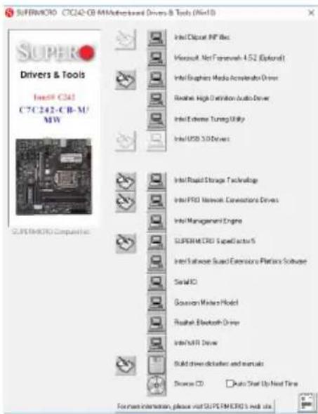
Driver/Tool Installation Display Screen

Note 1: Click the icons showing a hand writing on the paper to view the readme files for each item. Click on a computer icon to the right of an item to install this item (from top to bottom), one at a time. After installing each item, you must reboot the system before proceeding with the next item on the list. The bottom icon with a CD on it allows you to view the entire contents of the CD.
Note 2: When making a storage driver diskette by booting into a Driver CD, please set the SATA Configuration to "Compatible Mode" and configure SATA as IDE in the BIOS Setup. After making the driver diskette, be sure to change the SATA settings back to your original settings.
B-2 Configuring SuperDoctor® 5
The Supermicro SuperDoctor 5 is a hardware monitoring program that functions in a command-line or web-based interface in Windows and Linux operating systems. The program monitors system health information such as CPU temperature, system voltages, system power consumption, fan speed, and provides alerts via email or Simple Network Management Protocol (SNMP).
SuperDoctor 5 comes in local and remote management versions and can be used with Nagios to maximize your system monitoring needs. With SuperDoctor 5 Management Server (SSM Server), you can remotely control power on/off and reset chassis intrusion for multiple systems with SuperDoctor 5 or IPMI. SD5 Management Server monitors HTTP and SMTP services to optimize the efficiency of your operation.

Note: The default Username and Password for SuperDoctor 5 is ADMIN / ADMIN. The SuperDoctor 5 program and user's manual can be downloaded from the Supermicro website at http://www.supermicro.com/products/nfo/sms_sd5.cfm.
![SuperDoctor 5 Main info: Metherhood: CTB300 C3.46. Voltage Temperature Hard Disk [mean Temperature] Memory Select Language: English ACMINI: Local Status Chronic Range](/content/2026/05/981949/images/de1de16901af27c90f7de377343839dba7b3f111d6b312ecfee9ceb9e4e01165.jpg)
SuperDoctor 5 Interface Display Screen-I (Health Information)
Appendix C
UEFI BIOS Recovery Instructions
! Attention! Do not upgrade the BIOS unless your system has a BIOS-related issue. Flashing the wrong BIOS can cause irreparable damage to the system. In no event shall Supermicro be liable for direct, indirect, special, incidental, or consequential damages arising from a BIOS update. If you need to update the BIOS, do not shut down or reset the system while the BIOS is updating to avoid possible boot failure.
C-1 An Overview to the UEFI BIOS
The Unified Extensible Firmware Interface (UEFI) specification provides a software-based interface between the operating system and the platform firmware in the pre-boot environment. The UEFI specification supports an architecture-independent mechanism for add-on card initialization to allow the UEFI OS loader, which is stored in the add-on card, to boot up the system. UEFI offers a clean, hands-off control to a computer system at bootup.
C-2 How to Recover the UEFI BIOS Image
A UEFI BIOS flash chip consists of a recovery BIOS block and a main BIOS block (a main BIOS image). The recovery block contains critical BIOS codes, including memory detection and recovery codes for the user to flash a healthy BIOS image if the original main BIOS image is corrupted. When the system power is turned on, the recovery block codes execute first. Once this process is complete, the main BIOS code will continue with system initialization and the remaining POST (Power-On Self-Test) routines.

Note: Follow the BIOS Recovery instructions in Section C-3 for BIOS recovery when the main BIOS boot crashes. However, when the BIOS boot block crashes, you will need to follow the procedures to make a Returned Merchandise Authorization (RMA) request.
C-3 To Recover the Main BIOS Block Using a USB-Attached Device
This feature allows the user to recover the main BIOS image using a USB-attached device without additional utilities used. A USB flash device such as a USB Flash Drive, or a USB CD/DVD ROM/RW device can be used for this purpose. However, a USB hard disk drive cannot be used for BIOS recovery at this time. The file system supported by the recovery block is FAT (including FAT12, FAT16, and FAT32) which is installed on a bootable or non-bootable USB-attached device.
To perform UEFI BIOS recovery using a USB-attached device, follow the instructions below.
- Using a different machine to download the BIOS package for your motherboard or your system from the product page available on our website at www.supermicro.com.
- Extract the BIOS package to a USB device and rename the BIOS ROM file [BIOSname#.###] that is included in the BIOS package to SUPER.ROM for BIOS recovery use.
- Copy the SUPER.ROM file into the Root "\" directory of the USB device.

Note: Before recovering the main BIOS image, confirm that the SUPER.ROM file you have is the same version or a close version meant for your motherboard.
- Insert the USB device that contains the SUPER.ROM file into the system before you power on the system or when the following screen appears.
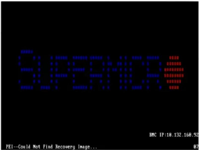
- After locating the SUPER.ROM file, the system will enter the BIOS Recovery menu as shown below.
![Aptio Setup Utility - Copyright (C) 2019 American Megatrends, Inc. Main Advanced Event Logs IPM1 Recovery Security Boot Save & Exit System booted from new image Partial update is not allowed SMBIOS Preservation [Enabled] ► Proceed with flash update Set this option to preserve SMBIOS +: Select Screen ↑↓: Select Item Enter: Select +/-: Change Opt. F1: General Help F2: Previous Values F3: Optimized Defaults F4: Save & Exit ESC: Exit Version 2.20.1276. Copyright (C) 2019 American Megatrends, Inc.](/content/2026/05/981949/images/a29e7988fd44477b631b4530ac7e35bc6b703aba5bfefe5ba16643affde88c59.jpg)

Note: At this point, you may decide if you want to start the BIOS recovery. If you decide to proceed with BIOS recovery, follow the procedures below.
- When the screen as shown above displays, use the arrow keys to select the item "Proceed with flash update" and press the
key. You will see the BIOS recovery progress as shown in the screen below.

Note: Do not interrupt the BIOS flashing process until it is complete.
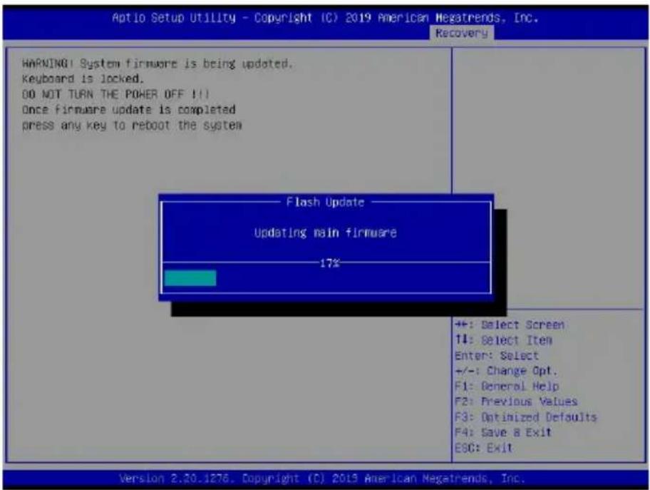
- After the BIOS recovery process is complete, press any key to reboot the system.
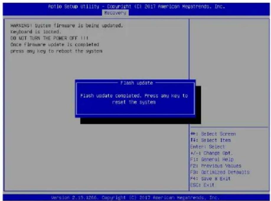

Note: It is recommended that you update your BIOS after BIOS recovery. Please refer to Chapter 3 for BIOS update instructions.
- Press
during system boot to enter the BIOS Setup utility. From the top of the tool bar, select Boot to enter the submenu. From the submenu list, select Boot Option #1 as shown below. Then, set Boot Option #1 to [UEFI AP:UEFI: Built-in EFI Shell]. Pressto save the settings and exit the BIOS Setup utility.
![Aptio Setup Utility - Copyright (C) 2017 American Megatrends, Inc. Main Advanced Event Logs IPML Security Boot Save & Exit Boot Configuration Boot mode select [DUAL] LEGACY to EFI support [Disabled] FIXED BOOT ORDER Priorities Boot Option #1 [UEFI MP:UEFI: Out...] Boot Option #2 [CD/DVD] Boot Option #3 [USB Hard Disk] Boot Option #4 [USB CD/DVD] Boot Option #5 [USB Key:SanDisk] Boot Option #6 [USB Floppy] Boot Option #7 [USB Lan] Boot Option #8 [Network:IBA GE SI...] Boot Option #9 [UEFI Hard Disk] Boot Option #10 [UEFI CD/DVD] Boot Option #11 [UEFI USB Hard Disk] Boot Option #12 [UEFI USB CD/DVD] Boot Option #13 [UEFI USB Key:UEFI...] Boot Option #14 [UEFI USB Floppy] Boot Option #15 [UEFI USB Lan] Boot Option #16 [UEFI Network] Boot Option #17 [Hard Disk] Add New Boot Option Sets the system boot order ◆: Select Screen T4: Select Item Enter: Select +/-: Change Opt. F1: General Help F2: Previous Values F3: Optimized Defaults F4: Save & Exit ESC: Exit Version 2.19.1268. Copyright (C) 2017 American Megatrends, Inc.](/content/2026/05/981949/images/2c2ce256e3339760149967d5546d1a84c69916a4b91306aaa8ce17a293b60027.jpg)
- When the UEFI Shell prompt appears, type fs# to change the device directory path. Go to the directory that contains the BIOS package you extracted earlier in Step 2. Enter flash.nsh BIOS-name#.### at the prompt to start the BIOS update process.
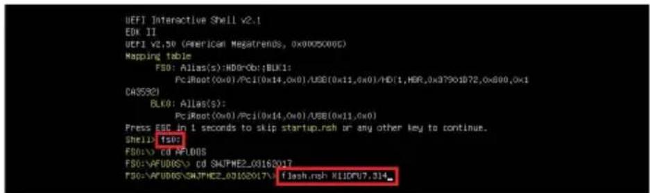

Note: Do not interrupt this process until the BIOS flashing is complete.
![Done. [ Access CMOS Part Ex ] Index 0x51: 0x10 Done. ********************************************************************** * • Program BIOS and ME (including FOT) regions... * ********************************************************************** AMI Firmware Update Utility v5.03.01.1317 Copyright (C)2017 American Megatrends Inc. All Rights Reserved. CPUID = 50652 Reading flash ......... done - ME Data Size checking . ok - FFS checksums ......... ok - Check RomLayout ......... Ok, Erasing Boot Block ......... done Updating Boot Block ......... done Verifying Boot Block ......... done _Erasing Main Block ......... 0x00132000 (OK)](/content/2026/05/981949/images/4d17e7c76286b16dc6af46ccecf6347c7822f2d141b113e9321e6f80d0845fc2.jpg)
- The screen above indicates that the BIOS update process has completed. Reboot the system when you see the screen below.
![Verifying NCB Block ......... done - Update success for FOR - Update success for IE. - - Successful Update Recovery Loader to OPRx!! - Successful Update MFS0!!- - Successful Update FTPRI!! - Successful Update MFS, IVB1 and IVB2!! - Successful Update FLOG and UTOE!! - HE Entire Image update success !! WARNING: System must power-off to have the changes take effect! Moving FS0:\AFUDOS\SKJPME2_03162017\rdt\x64.ef1 -> FS0:\AFUDOS\SKJPME2_03162017\f df1.snc - [ok] Moving FS0:\AFUDOS\SKJPME2_03162017\afuefix64.ef1 -> FS0:\AFUDOS\SKJPME2_0316201 7\afuefix.snc - [ok] ********************************************************************** * * Please ignore this 'Shell: Cannot read from file - Device Error' * warning message due to it does not impact flashing process. * ********************************************************************** Deleting ' Delete successful. FS0:>](/content/2026/05/981949/images/643b8c27e1f0fc6df7b0ebd1ee600da380ce26d4614b763d7c7652b7dc42dae2.jpg)
Notes
(Disclaimer Continued)
The products sold by Supermicro are not intended for and will not be used in life support systems, medical equipment, nuclear facilities or systems, aircraft, aircraft devices, aircraft/emergency communication devices or other critical systems whose failure to perform be reasonably expected to result in significant injury or loss of life or catastrophic property damage. Accordingly, Supermicro disclaims any and all liability, and should buyer use or sell such products for use in such ultra-hazardous applications, it does so entirely at its own risk. Furthermore, buyer agrees to fully indemnify, defend and hold Supermicro harmless for and against any and all claims, demands, actions, litigation, and proceedings of any kind arising out of or related to such ultra-hazardous use or sale.