50-120 - Sander RIKON - Free user manual and instructions
Find the device manual for free 50-120 RIKON in PDF.


| Brand | RIKON |
| Model | 50-120 |
| Product Type | Random Orbital Sander |
| Pad Size | 6 inches (150 mm) |
| Orbit Diameter | 3/16 inch (4.8 mm) |
| Speed Range | 10,000 - 14,000 OPM |
| Variable Speed | Yes, with dial control |
| Power Source | Corded electric |
| Voltage | 120V AC, 60 Hz |
| Amperage | 5 Amps |
| Power Cord Length | 8 feet (2.4 m) |
| Dust Collection | Built-in dust bag with 1-inch vacuum adapter |
| Weight | 3.5 lbs (1.6 kg) |
| Dimensions (L x W x H) | 10 x 6 x 7 inches (25.4 x 15.2 x 17.8 cm) |
| Body Material | Aluminum and polymer |
| Soft Grip Handle | Yes, overmolded rubber |
| Safety Lock | Yes, paddle switch with lock-on |
| Hook-and-Loop Pad | Yes, for quick paper changes |
| Accessories Included | Dust bag, 5 each of 80, 120, 220 grit sanding discs |
| Warranty | 5 years limited |
| Certifications | ETL listed |
Frequently Asked Questions - 50-120 RIKON
User questions about 50-120 RIKON
0 question about this device. Answer the ones you know or ask your own.
Ask a new question about this device
Download the instructions for your Sander in PDF format for free! Find your manual 50-120 - RIKON and take your electronic device back in hand. On this page are published all the documents necessary for the use of your device. 50-120 by RIKON.
USER MANUAL 50-120 RIKON
6" X 48"Belt & 10"Disc Sander

natural_image
Rikon industrial machine with circular blade and metal frame (no visible text or symbols)
Intertek 4001824
Operator's Manual
Record the serial number and date of purchase in your manual for future reference.
Serial Number: Date of purchase:
For technical support or parts questions, email techsupport@rikontools.com or call toll free at (877)884-5167
Operator Safety: Required Reading
IMPORTANT! Safety is the single most important consideration in the operation of this equipment. The following instructions must be followed at all times.
There are certain applications for which this tool was designed. We strongly recommend that this tool not be modified and/or used for any other application other than that for which it was designed. If you have any questions about its application, do not use the tool until you have contacted us and we have advised you.
General Safety Warnings
KNOW YOUR POWER TOOL. Read the owner's manual carefully. Learn the tool's applications, work capabilities, and its specific potential hazards.
▲DANGER | ALWAYS GROUND ALL TOOLS.If your tool is equipped with a three-pronged plug, you must plug it into a three-hole electric receptacle.If you use an adapter to accommodate a two-pronged receptacle, you must attach the adapter plug to a known ground. Never remove the third prong of the plug.ALWAYS AVOID DANGEROUS ENVIRONMENTS.Never use power tools in damp or wet locations. Keep your work area well lighted and clear of clutter. |
▲DANGER | ALWAYS REMOVE THE ADJUSTING KEYS AND WRENCHES FROM TOOLS AFTER USE.Form the habit of checking to see that keys and adjusting wrenches are removed from the tool before turning it on.ALWAYS KEEP YOUR WORK AREA CLEAN. Cluttered areas and benches invite accidents. |
▲DANGER | ALWAYS KEEP VISITORS AWAY FROM RUNNING MACHINES.All visitors should be kept a safe distance from the work area.ALWAYS MAKE THE WORKSHOP CHILDPROOF.Childproof with padlocks, master switches, or by removing starter keys. |
▲DANGER | NEVER OPERATE A TOOL WHILE UNDER THE INFLUENCE OF DRUGS,MEDICATION, OR ALCOHOL. |
▲DANGER | ALWAYS WEAR PROPER APPAREL.Never wear loose clothing or jewelry that might get caught in moving parts. Rubber-soled footwear is recommended for the best footing. |
▲DANGER | ALWAYS USE SAFETY GLASSES AND WEAR HEARING PROTECTION.Also use a face or dust mask if the cutting operation is dusty. |
▲DANGER | NEVER OVERREACH.Keep your proper footing and balance at all times. |
▲DANGER | NEVER STAND ON TOOLS.Serious injury could occur if the tool is tipped or if the cutting tool is accidentally contacted. |
DANGER
ALWAYS DISCONNECT TOOLS.
Disconnect tools before servicing and when changing accessories such as blades, bits, and cutters.

ALWAYS AVOID ACCIDENTAL STARTING.
Make sure switch is in "OFF" position before plugging in cord.
NEVER LEAVE TOOLS RUNNING UNATTENDED.
DANGER
ALWAYS CHECK FOR DAMAGED PARTS.

Before initial or continual use of the tool, a guard or other part that is damaged should be checked to assure that it will operate properly and perform its intended function. Check for alignment of moving parts, binding of moving parts, breakage of parts, mounting, and any other conditions that may affect its operation. A guard or other damaged parts should immediately be properly repaired or replaced.
Special Safety Rules For Belt & Disc Sanders
- Do not operate this machine until you have read all of the following instructions.
- Do not attempt to operate this machine until it is completely assembled.
- Do not turn ON this machine if any pieces are missing.
- If you are not familiar with the operation of the machine, obtain assistance from a qualified person.
- It is highly recommended that this machine be firmly mounted to a flat and secure work surface or stand.
- Always wear protective eye wear prior to operating this machine.
- Do not operate this machine if you are under the influence of drugs and/or alcohol.
- Remove all jewelry prior to operating this machine.
- Do not wear any gloves while operating this machine.
- Always make sure the power switch is in the OFF position prior to plugging in the machine.
- Always make sure the power switch is in the OFF position when doing any assembly or setup operation.
- Always wear a dust mask and use adequate dust collection and proper ventilation. Use of sanders can produce harmful particles while sanding certain types of woods.
- The use of any accessories or attachments not recommended may cause injury to you and damage your machine.
- This machine must be properly grounded.
- Abrasive discs and belts should be the recommended width and length of the manufacturer.
- Always keep your face and hands clear of moving parts such as belts and pulleys.
- Keep power supply cords free of moving parts of the sander. Damaged cords can result in electric shock.
- Maintain a 1/16" clearance between the sanding disc, sanding belt and tables.
- Always support the workpiece with the table or backstop.
- Remove material or debris from the work area. Keep work area neat and clean.
SAVE THESE INSTRUCTIONS.
Refer to them often.
This owner's manual is not a teaching aid. Use of this owner's manual is intended to show assembly, adjustments, and general use.
Table of Contents
Safety Warnings....2-3
Sander Safety Rules ....3
Specifications 4
Contents of Package ....5
Assembly 6-8
Electrical Requirements....9
Operation....10-11
Maintenance 12
Changing the Motor Belt....12
Trouble Shooting....13
Wiring Diagram....13
Parts Diagram 14
Parts List....15
Notes 16-18
Warranty 19
Specifications
Motor 3/4 HP
Amps 10 A
Volts, Hertz 110 V, 60 Hz
Belt Size 6" x 48"
Belt Speed (no load) 2,030 SFPM
Belt Table Tilt 0° - 90°
Belt Fence (LxH) 7-7/8" x 4-3/4"
Disc Size (PSA) Diameter 10"
Disc Speed (no load) 1,720 RPM
Disc Table Size (LxW) 4" x 8"
Disc Table Tilt 0° - 45°
Miter Gauge 'T' Slot 3/8" x 3/4"
Dust Port (1) 2-1/2" OD, 2-5/16" ID
Overall Size (LxWxH) 28-1/4" x 17-1/4" x 16"
Base Size (LxW) 22" x 10-1/4"
Net Weight 92 lbs.
NOTE: The specifications, photographs, drawings and information in this manual represent the current model when the manual was prepared. Changes and improvements may be made at any time, with no obligation on the part of Rikon Power Tools, Inc. to modify previously delivered units. Reasonable care has been taken to ensure that the information in this manual is correct, to provide you with the guidelines for the proper safety, assembly and operation of this machine.
California Proposition 65 Warning
WARNING: Some dust created by power sanding, sawing, grinding, drilling, and other construction activities contains chemicals known to the State of California to cause cancer and birth defects or other reproductive harm. Your risk from exposure to these chemicals varies, depending on how often you do this type of work. To reduce your exposure, work in a well-ventilated area and with approved safety equipment, such as dust masks that are specially designed to filter out microscopic particles.
For more detailed information about California Proposition 65 log onto rikontools.com.
Contents of Package
When unpacking, check to make sure the following parts are included. If any parts are missing or broken, please call RIKON Power Tools at the number on the cover of this manual as soon as possible.
Carton Contents
Item Description
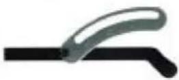
A Belt & disc sander assembly 1
B Sanding disc
C Table support w/scale 1
D Table support 1
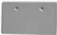
E Work table for belt 1
F Miter Gauge
G Work table for disc 1
H Locking knob for table support 2
I Mount, support table 1
J Mount, support table w/indicator 1
K Bag of loose parts 1
L Owner's manual 1
A

natural_image
Exterior view of a vintage portable electronic device with a circular lens and control panel (no visible text or symbols)Qty
G

B

C
D

E
H

|

J

K

F

L

List of loose parts in bag
Description
Sunk head screw M6x16 2

Washer 6mm 2

Knurled nut M6 2

Hex. bolt 4

Lock washer 4
Qty
Description
Qty

Pan head screw M6x16 4

Lock washer 6mm 4

Washer 6mm 2

Hex "L" wrench 3mm 1
Hex "L" wrench 6mm 1
Assembly
Securing Sander Base Assembly to Workbench
The sander base must be secured before using. Attach a large C-Clamp to each side of the sander and the workbench. Or, permanently mount following the instructions below:
- Place the sander on the workbench in its final operating location.
- Place a pencil through the mounting holes of the sander base (42) and mark the hole locations on workbench.
-
Remove the sander and drill four 3/8 inch holes through the workbench.
-
Align the sander base over the holes and secure using four 5/16 inch screws (or larger) and hex nuts. (See Fig. 01)
Mounting Sanding Disc and Guard
- Locate the sanding disc (22) and peel the backing off of the disc.
- Align the perimeter of the sanding disc over plate. When aligned, press the disc firmly onto the disc.
- Position the disc guard (27) onto the lower portion of the sanding disc so that the mounting holes align.
- Using a Phillips screwdriver, fasten two pan head screws (found in parts bag) through the disc guard. (See Fig. 02)
Changing the Sanding Disc
The sandpaper disc can be removed with the table installed, or with the table removed to give more working access to the disc, if needed.
- Peel off the used abrasive disc from the metal sanding disc. A putty knife may help in this process.
-
Make sure that the disc plate is clean of any residue. Mineral spirits will soften the PSA adhesives. Rotate the disc by hand may be necessary to get access to all of the disc surface.
-
Peel the backing off the new PSA 10" sanding disc, then center and press the sanding disc onto the metal disc plate.
-
Replace the sanding table if it was removed.
WARNING THE MACHINE MUST NOT BE PLUGGED IN AND THE POWER SWITCH MUST BE IN THE 'OFF' POSITION UNTIL ASSEMBLY IS COMPLETE.

natural_image
Hand operating a black RIKOMA machine with a handle, no visible text or symbols on the device itself.Fig. 01

Fig. 02

natural_image
Close-up of hands operating a mechanical device with a white panel and black base (no visible text or symbols)Fig. 03
Installing the Belt Table
- Place the work table for belt on the work support.
- Insert two countersink head screws through the work table and the work support slot.
- Put a 6mm washer and a wing nut on the screw and tighten. (See Fig. 03)
Assembly
Installing the Disc Table Assembly
Warning: To avoid jamming the workpiece or fingers between the table and sanding surface, the table edge should be a maximum of 1/16 inch from the sanding surface.
- Use two M6x16 pan head screws to fasten the table support mount to the front of the sander.
- Place the support table with scale onto the table support mount.
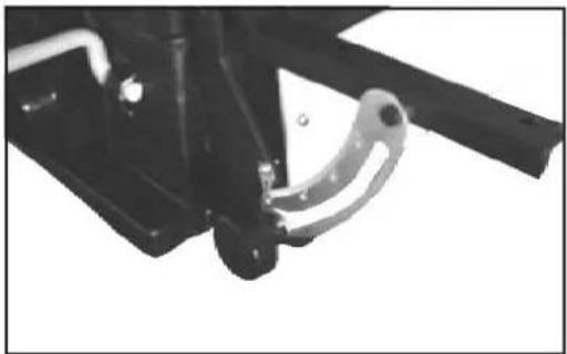
- Put a 6mm flat washer on the table lock knob, and place the knob into the tilt scale plate and mount. Hand tighten it only at this time. (See Fig. 04)
- Place the table onto table support; align the four screws which are pre-assembled under the table with the holes of table support. (See Fig. 05)
- Put the external lock washer and hex nut onto the screws, and tighten.
- Adjust the table and re-tighten the table lock knobs.
- Loosen the four M6 hex nuts under the table.
- Use a 1/16 inch drill bit as a spacer. Place the drill bit between the disc and the front edge of the table. Hold the table against the 1/16 inch drill bit and tighten the four M6 hex nuts. (See Fig. 06)
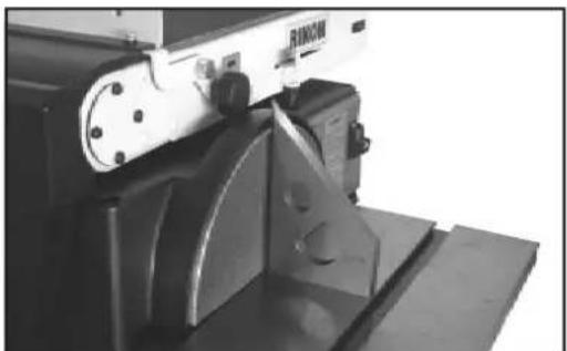
Warning: To avoid injury from accidental start, make sure the machine is unplugged before making any adjustments. - Using a combination square, check the angle of the work table with the disc. (See Fig. 07)
- If the table is not 90 degrees with the disc, loosen the table lock knob screw and tilt the table.
- Adjust the worktable square to the disc and re-tighten the table lock knob.
- Adjust the pointer to the zero mark on the scale plate.
Leveling Table Assembly
natural_image
Close-up of a mechanical linkage component with no visible text or symbolsFig. 04

natural_image
Black-and-white photo of a mechanical device with a flat top and side panels, no visible text or symbols.Fig. 05

natural_image
Close-up of a mechanical device with a circular component and control panel (no visible text or symbols)Fig. 06
natural_image
Close-up of a mechanical device with a metallic bracket and mounting base (no visible text or symbols)Fig. 07
Assembly
Installing the Sanding Belt
Warning: To avoid injury from accidental start, make sure the machine is unplugged before making any adjustments.
On the under side of the sanding belt, you will find a "direction arrow". The sanding belt must run in the direction of this arrow, so that the splice does not come apart.
- Slide the tension lever to the right to release the belt tension. (See Fig. 08)
- Place the sanding belt over the drums with the direction arrow pointing in the proper direction. (See Fig. 09) Make sure the belt is centered on both drums.
- Slide tension lever to the left to apply belt tension.
- Tighten the hex socket screw (59) when the bed is in the desired position for sanding. See page 10.
Tensioning and Tracking
- Plug in the power cord. Turn the switch "ON" and immediately "OFF", noting if the belt tends to slide off the idler drum or drive drum.
- If the sanding belt moves toward the disc, turn the tracking knob clockwise 1/4 turn. (See Fig. 10)
- If the sanding belt moves away from the disc, turn the tracking knob counterclockwise 1/4 turn.
- Turn the switch "ON" and immediately "OFF" again, noting the belt movement. Readjust the tracking knob if necessary.
On/Off Switch
The On/Off Locking Switch needs to have the switch key inserted before the switch can be used (key located in parts bag). This feature prevents unauthorized use of the sander. (See Fig. 11)
CAUTION: Never walk away from sander when machine is running. Always lock the switch in the Off position and unplug from the power supply when not in use.

natural_image
Close-up of a hand holding a white tool on a device labeled 'RIMON' (no additional text or symbols visible)Fig. 08

Fig. 09

Fig. 10
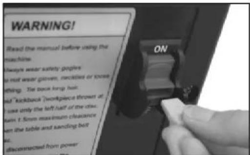
Fig. 11
Electrical Requirements
In the event of a malfunction or breakdown, grounding provides a path of least resistance for electric current to reduce the risk of electric shock. This tool is equipped with an electric cord having an equipment-grounding conductor and a grounding plug. The plug must be plugged into a matching outlet that is properly installed and grounded in accordance with all local codes and ordinances.
Do not modify the plug provided. If it will not fit the outlet, have the proper outlet installed by a qualified electrician.
Improper connection of the equipment-grounding conductor can result in a risk of electric shock. The conductor, with insulation having an outer surface that is green with or without yellow stripes, is the equipment-grounding conductor. If repair or replacement of the electric cord or plug is necessary, do not connect the equipment-grounding conductor to a live terminal.
Check with a qualified electrician or service personnel if the grounding instructions are not completely understood, or if in doubt as to whether the tool is properly grounded.
Use only three wire extension cords that have three-prong grounding plugs and three-pole receptacles that accept the tool's plug.*
Repair or replace a damaged or worn cord immediately.
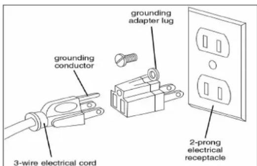
This tool is intended for use on a circuit that has an outlet that looks the one illustrated in Figure A below. The tool has a grounding plug that looks like the grounding plug as illustrated in Figure A below. A temporary adapter, which locks like the adapter as illustrated in Figure B below, may be used to connect this plug to a two-pole receptacle, as shown in Figure B if a properly grounded outlet is not available.** The temporary adapter should only be used until a properly grounded outlet can be installed by a qualified electrician. The green colored rigid ear or tab, extending from the adapter, must be connected to a permanent ground such as a properly grounded outlet box.
* Canadian electrical codes require extension cords to be certified SJT type or better.
** Use of an adapter in Canada is not acceptable.

Fig. A Fig. B
NOTE: See page 13 for the 50-120 Wiring Diagram.
Operation
Bevel Sanding
The work table can be tilted from 0 to 45 degrees for bevel sanding. Loosen the table lock knob and tilt the work table to desired angle as shown. (See Fig. 12) Re-tighten the table lock knob.
Warning: To avoid jamming the workpiece or fingers between the table and sanding surface, the table should repositioned on the table support to retain a maximum of 1/16" distance between the sanding surface and the table.
Positioning the Belt Bed
A bed locking hex socket head screw locks the belt bed in a vertical or horizontal position.
To adjust vertical position:
-
Remove the work support.
-
Loosen the hex socket head locking screw (59) using a 1/4 inch hex wrench. (See Fig. 13)
-
Position the belt bed vertically as shown and tighten the hex socket head locking screw.
Surface Sanding on the Sanding Belt
Warning: To avoid injury from slips, jams or thrown pieces, adjust the backstop to clear the sanding surface by no more than 1/16th of and inch. When checking clearance between the belt and work support, use a 1/16" drill bit as a spacer gauge. (See Fig. 14)
-
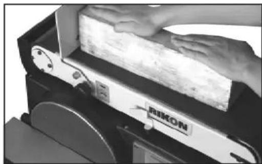
Hold the workpiece firmly with both hands, keeping fingers away from the sanding belt.
-
Keep the end butted against the backstop and move the work evenly across the sanding belt. Use extra caution when sanding very thin pieces. (See Fig. 15)
-
For sanding long pieces, remove the work support.
-
Apply only enough pressure to allow the sanding belt to remove material.

natural_image
Close-up of a mechanical device with a curved panel and metal cladding (no visible text or symbols)Fig. 12
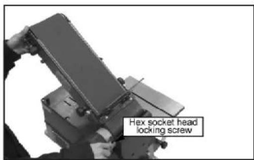
Fig. 13

natural_image
Close-up of a mechanical device with a white panel and black base, showing a textured surface (no visible text or symbols)Fig. 14
natural_image
Close-up of a hand pressing down on a silicon wafer with a label 'RIMON' (no readable text or symbols beyond label)Fig. 15
Operation
End Sanding on the Sanding Belt
To sand the end of a long workpiece, it is recommended to sand with the belt in the vertical position.
- To raise the belt to the vertical position, follow the instructions in "Positioning Belt Bed" on the previous page.
- Install the work table assembly.
- Move the work evenly across the sanding belt. (See Fig. 16)
Sanding Curved Edges
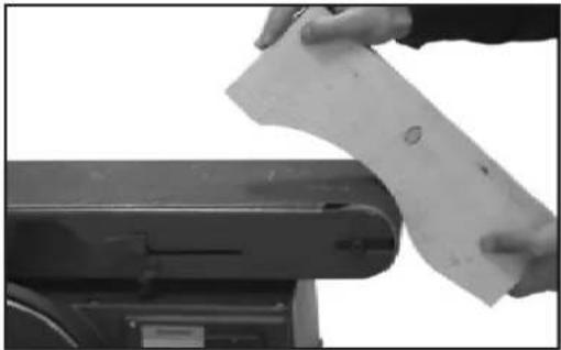
Always sand inside curves on the idler drum as shown.(See Fig. 17)
Warning: Never attempt to sand the ends of a workpiece on the idler drum. Applying the end of the workpiece to the idler drum could cause the workpiece to fly up and result in an injury.
Always sand outside curves on the left side of center on the sanding disc as shown. The downward rotating sanding disc will safely force the work down onto the work table where it can be safely controlled.(Fig. 18)
Warning: Applying the workpiece to the right side of the disc could cause a workpiece to fly up (kickback) and result in an injury.
Sanding Small End Surfaces on the Sanding Disc
Note: Use of a miter gauge is recommended for this operation.
Always move the work across left side of center on the sanding disc face as shown. (See Fig. 19)
Warning: Applying the workpiece to the right side of the disc could cause workpiece to fly up( kickback) and result in an injury.

Fig. 16
natural_image
Close-up of hands holding a sheet of paper over a mechanical device (no visible text or symbols)Fig. 17
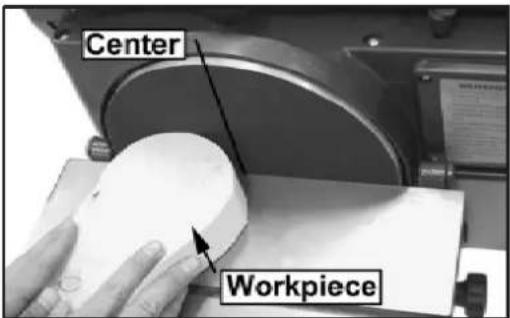
Fig. 18

Fig. 19
Maintenance
Warning: For your safety, remove the plug from power source outlet before adjusting, maintaining, of lubricating your belt and disc sander.
- Apply a light coat of paste wax to the work table to make feeding stock easier, and reduce rust.
- Use compressed air to frequently blow out dust and debris from the sander and motor. (See Fig. 20)
Warning: To avoid electrocution or fire, any repairs to electrical systems should be done only by qualified service technicians. Unit must be reassembled exactly to factory specifications.
- If the power cord is worn, cut, or damaged in any way, have it repaired immediately.
Changing the Motor Belt
- Using a Phillips screwdriver, remove the three pan head screws located in the cover. (See Fig. 21)
- Remove the cover.
- Loosen four M8 hex head screws to allow the pulleys to shift enough to place belt around them. Place the belt around the motor pulley and drive pulley as shown. (See Fig. 22)
- Adjust tension of the belt by putting a wrench in the adjusting gap. Push up on the wrench to tighten the tension between the two pulleys.
- Tighten the four M8 hex head screws carefully.
- Test belt tension by placing fingers on either side of the belt and squeeze. There should be about a 1/4 inch 'give', or deflection, to the belt. (See Fig. 23)
Note: Too much tension on the pulley belt may cause increased noise and over load the motor. Not enough tension on the pulley belt may cause the belt to fail prematurely.
- Locate the pulley cover and position it inside the edges of pulley housing.
- Using a Phillips screwdriver, reinstall and tighten the three pan head screws.
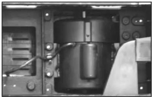
natural_image
Interior view of a mechanical device with internal components and wiring (no visible text or symbols)Fig. 20
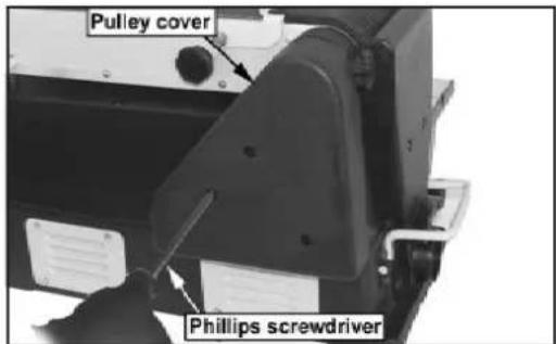
Fig. 21

Fig. 22

natural_image
Close-up of a hand using a mechanical belt drive a chain on a device (no visible text or symbols)Fig. 23
Troubleshooting
| SYMPTOM PROBABLE CAUSE REMEDY | ||
| Sander does not operate | 1. Not plugged into wall outlet.2. Locking key is not inserted.3. Power switch defective.4. Motor or wiring problem. 4. Take to a | 1. Plug into wall outlet.2. Insert locking key.3. Replace power switch.qualified technician. |
| Motor slows when sanding 1. | Timing belt is too tight.2. Applying too much pressure 2. Apply on work piece. piece when sanding. | 1. Decrease tension.less pressure to work |
| Sanding Belt runs off drums 1. | Not tracking proplerly. | 1. Adjust tracking. |
| Wood burns while sanding | 1. Sanding Disc or Belt is loaded with debris. | 1.Clean or replace disc or belt. |
| Sander makes excessive noise | 1. Timing belt too tight, bearings need oil. | 1. Decrease tension, oil bearings. |
Wiring Diagram

Parts Diagram

KEY
| NO. | DESCRIPTION | PART NO. |
| 1 | Sanding belt 6" x 48" | 1-JL61020032 |
| 2 | Bed | 1-JL61021000-050W |
| 3 | Knob | 1-JL20061101/2-001S |
| 4 | Washer | 1-WSH8GB96B |
| 5 | Wing screw | 1-JL61040006 |
| 6 | Sunk head screw M6x16 | 1-M6X16GB818B |
| 7 | Work table for belt | 1-JL61040008-050W |
| 8 | Work support, for sander belt | 1-JL61040003A-117U |
| 8A | Work support plastic belt shroud | 1-JL61040007-0015 |
| 9 | Lock pin, work support | 1-JL61040004 |
| 10 | Wing nut M6 | 1-JL20061003-001S |
| 11 | Lock washer-helical 5mm | 1-WSH5GB862D2Z |
| 12 | Pan head screw M5x8 | 1-M5X14GB818B |
| 13 | Pan head screw M5x16 | 1-ST4D2X25GB845B |
| 14 | Switch housing | 1-JL60062001-049S |
| 15 | No-volt switch | 1-J-9301B |
| 17 | Bearing spacer | 1-JL61020008 |
| 18 | Bearing cap | 1-JL61020007 |
| 19 | Socket head screw M8x10 | 1-M8X10GB80B |
| 20 | Drive drum | 1-JL61020006 |
| 21 | Cover, switch housing | 1-JL60062002-049S |
| 22 | Pad - 10" dia. sandpaper | 1-JL61020033 |
| 23 | Screw-pan cross M6x12 | 1-M6X10GB70Z |
| 24 | Disc | 1-JL61030001 |
| 25 | Support, sanding disc | 1-JL61030002A |
| 26 | Tapping screw M4x12 | 1-M5X40GB70Z |
| 27 | Disc guard | 1-JL61010005-050W |
| 28 | Disc shroud | 1-JL61010006-001S |
| 29 | Hex nut M6 | 1-M6GB6170Z |
| 30 | Pan head screw M6x16 | 1-M6X16GB5781Z |
| 1a | Mount, table support, left | 1-JL61030005-001Y |
| 1b | Mount, table support, right | 2-JL61034000-001Y |
| 2a | Table support, left | 2-JL61032000-001Y |
| 2b | Table support,right | 2-JL61033000-001Y |
| 33 | Table | 1-JL61030010-001G |
| 34 | Dust collector | 1-JL61010003-001S |
| 35 | Pan head screw M5x16 | 1-M5X16GB818B |
| 36 | Clamp handle | 1-JL61010014-001Y |
| 37 | Handle | 1-JL61010013-050W |
| 38 | Pan head screw M5x16 | 1-M6X16GB818B |
KEY
| NO. | DESCRIPTION | PART NO. |
| 39 | Cast base | 1-JL61010001-001G |
| 40 | Motor cover | 1-JL61010002-001S |
| 41 | Safety guard, sanding belt lower | 1-JL61010012-001S |
| 42 | Pan head screw M5x8 | 1-M5X10GB818Z |
| 43 | Thread M6x145 | 1-M6X145GB818Z |
| 44 | Rubber sleeve | 1-JL61010011-001S |
| 45 | Support stem | 1-JL61010010 |
| 46 | Lock base sander belt | 1-JL61020026-001G |
| 47 | Motor | 1-G3512674 |
| 48 | Hex head screw | 1-M8X16GB5781Z |
| 49 | Lock washer | 1-WSH8GB93Z |
| 50 | Drive pulley | 1-JL61020027 |
| 51 | Countersink washer | 1-WSH6GB5287Z |
| 52 | Drive pulley | 1-JL61020001 |
| 53 | Pulley cover | 1-JL61010004-001S |
| 54 | Timing belt | 1-JL61020034 |
| 55 | Drive pulley | 1-JL61020002 |
| 56 | Flat head screw M5x25 | 1-M6X20GB70Z |
| 57 | Bearing support | 1-JL61020004 |
| 58 | Lock plate sander plate | 1-JL61020005-050A |
| 59 | Hex socket cap screw M8x25 | 1-M8X25GB5783B |
| 60 | Retaining ring 15mm | 1-CLP15GB894D1B |
| 61 | Ball bearing | 1-BRG80202GB278 |
| 62 | Drive shaft | 1-JL61020025 |
| 63 | Pan head screw M5x16 | 1-M5X16GB818B |
| 64 | Rubber washer | 1-JL61020021-001S |
| 65 | Tension lever | 1-JL61020023-050W |
| 66 | Lever spacer | 1-JL61020013 |
| 67 | Rubber washer | 1-JL60020018 |
| 68 | Index spring | 1-JL61020020 |
| 69 | Rubber bushing | 1-JL61020022 |
| 70 | Retaining ring 12mm | 1-CLP12GB894D1B |
| 71 | Ball bearing | 1-BRG80101GB278 |
| 72 | Idler drum | 1-JL61020017 |
| 73 | Idler shaft | 1-JL61020016 |
| 74 | Drum guide | 1-JL61022000 |
| 75 | Index spring | 1-JL61020015 |
| 76 | Power cord w/plug | 1-JL20072101 |
| 77 | “D” shape rubber bushing | 1-JL61010009-001S |
NOTE: Please reference the Manufacturer's Part Number when calling for Replacement Parts. For Parts under Warranty, the serial number of your machine is required.
Notes
Use this section to record maintenance, service and any calls to Technical Support:
Notes
Use this section to record maintenance, service and any calls to Technical Support:
Notes
Use this section to record maintenance, service and any calls to Technical Support:
RIKON
POWER TOOLS
5-Year Limited Warranty
RIKON Power Tools Inc. ("Seller") warrants to only the original retail consumer/purchaser of our products that each product be free from defects in materials and workmanship for a period of five (5) years from the date the product was purchased at retail. This warranty may not be transferred.
This warranty does not apply to defects due directly or indirectly to misuse, abuse, negligence, accidents, repairs, alterations, lack of maintenance or normal wear and tear. Under no circumstances will Seller be liable for incidental or consequential damages resulting from defective products. All other warranties, expressed or implied, whether of merchantability, fitness for purpose, or otherwise are expressly disclaimed by Seller. This warranty does not cover products used for commercial, industrial or educational purposes.
This limited warranty does not apply to accessory items such as blades, drill bits, sanding discs, grinding wheels or belts and other related items.
Seller shall in no event be liable for death, injuries to persons or property, or for incidental, contingent, special, or consequential damages arising from the use of our products.
To take advantage of this warranty proof of purchase documentation, which includes date of purchase and an explanation of the complaint, must be provided.
The Seller reserves the right to effect at any time, without prior notice, those alterations to parts, fittings, and accessory equipment which they may deem necessary for any reason whatsoever.
To take advantage of this warranty, please fill out the enclosed warranty card and send it to:
RIKON Warranty
16 Progress Rd.
Billerica, MA 01821
The card must be entirely completed in order for it to be valid. If you have any questions please contact us at 877-884-5167 or warranty@rikontools.com.

For more information:
16 Progress Road
Billerica, MA 01821
877-884-5167 / 978-528-5380
techsupport@rikontools.com

- 6" X 48"Belt & 10"Disc Sander
- Operator's Manual
- Operator Safety: Required Reading
- General Safety Warnings
- DANGER
- ALWAYS DISCONNECT TOOLS.
- ALWAYS AVOID ACCIDENTAL STARTING.
- ALWAYS CHECK FOR DAMAGED PARTS.
- Special Safety Rules For Belt & Disc Sanders
- SAVE THESE INSTRUCTIONS.
- Refer to them often.
- Table of Contents
- Specifications
- California Proposition 65 Warning
- Contents of Package
- Carton Contents
- Item Description
- List of loose parts in bag
- Description
- Qty
- Assembly
- Securing Sander Base Assembly to Workbench
- Mounting Sanding Disc and Guard
- Changing the Sanding Disc
- Installing the Belt Table
- Installing the Disc Table Assembly
- Leveling Table Assembly
- Installing the Sanding Belt
- Tensioning and Tracking
- On/Off Switch
- Electrical Requirements
- Operation
- Bevel Sanding
- Positioning the Belt Bed
- Surface Sanding on the Sanding Belt
- End Sanding on the Sanding Belt
- Sanding Curved Edges
- Sanding Small End Surfaces on the Sanding Disc
- Maintenance
- Changing the Motor Belt
- Troubleshooting
- Wiring Diagram
- Parts Diagram
- Notes
- RIKON
- POWER TOOLS
- 5-Year Limited Warranty
Brand : RIKON
Model : 50-120
Category : Sander