
FC-3 - Coffee maker Newco - Free user manual and instructions
Find the device manual for free FC-3 Newco in PDF.


| Product Type | Commercial Coffee Brewer |
| Brand | Newco |
| Model | FC-3 |
| Electrical Requirements | 120/240 V AC, 50/60 Hz (as per serial tag) |
| Water Pressure Requirement | Minimum 20 psi; use 1/4" copper tubing for runs less than 25 ft, 3/8" for longer runs |
| Brew Water Temperature | 195°F (adjustable via thermostat; lower for high altitudes) |
| Brew Volume Adjustment | Adjustable timer; turn clockwise to increase, counterclockwise to decrease |
| Height Adjustment | Telescoping column with spring lock and detents; adjust to fit various vessels |
| Warming Function | Available on warmer models (red-lighted rocker switches); thermal dispensers on thermal models |
| Hot Water Dispensing | Hot water faucet (depress handle); note: ensure power switch is on to refill tank |
| Auto Calibration | Set timer to max, start brew, then slowly turn back to stop at desired volume |
| Water Tank Fill Procedure | Depress start button while plugging in to fill tank; otherwise error light may flash |
| Error Indication | Auto Arm light flashes if water not sensed within 1 minute; reset by power cycling |
| Warranty (Parts and Labor) | 1 year parts and labor; 3 years parts for electronic boards and controls |
| User-Replaceable Parts | Faucet seat cups, sight gauge tubes, washers, o-rings, tubing, seals, gaskets |
| Cleaning Restrictions | Do not use muriatic or hydrochloric acid; use approved descalers |
| Installation Requirements | Cold water line, copper tubing, saddle valve with minimum 1/8" porthole |
| Country of Origin | Manufactured by Newco, USA (assumed based on warranty address in St. Charles, MO) |
Frequently Asked Questions - FC-3 Newco
User questions about FC-3 Newco
0 question about this device. Answer the ones you know or ask your own.
Ask a new question about this device
Download the instructions for your Coffee maker in PDF format for free! Find your manual FC-3 - Newco and take your electronic device back in hand. On this page are published all the documents necessary for the use of your device. FC-3 by Newco.
USER MANUAL FC-3 Newco
Installation/Operation Manual

natural_image
Row of industrial coffee brewing machines with various designs and colors, no visible text or labelsFC-S3 FC-5 FC-3 FC-TD FC-AP FC-LD FC-S
FC SERIES BREWERS

natural_image
Exterior view of a modern industrial water treatment machine (NEWCO) with control panel and water drop mechanism (no readable text or symbols)FC-TS
Table of Contents
Plumber's Install Instructions ____ Page: 3
Brewer Set Up Procedures ____ Pages: 3 & 4
Coffee Preparation Procedures Page: 4
Telescoping Brewer Operation Procedures ____ Pages: 4 thru 6
Temperature & Volume Adjustment Settings ____ Pages: 7 & 8
Wiring Schematics Page: 9
Addendum to Operation Manual Page: 10
Product Warranty ____ Page: 11
PLUMBER'S INSTALLATION INSTRUCTIONS:
-
Flush water line before installing brewer. Brewer should be connected to cold water line for best performance – operation.
-
Water pressure should be at 20 lbs. For less than a 25 ft. run, use 1/4" copper tubing and connect to a 1/2" or larger water line. For longer runs, use 3/8" copper tubing and connect to a 1/2" or larger water line. An adaptor fitting should be used to connect to the brewer.
-
If installed with a saddle valve, the valve should have a minimum 1/8" porthole up to 25 ft. In excess of 25 ft., use a 5/16" porthole.
-
Connect incoming water line to the flow control attached to the elbow extending from the back of the brewer. Manufacturer recommends using copper tubing to make connection.
BREWER SET UP PROCEDURES:
WARNING: READ AND FOLLOW INSTALLATION INSTRUCTIONS BEFORE PLUGGING OR WIRING IN THE BREWER TO AN ELECTRICAL CIRCUIT. WARRANTY WILL BE VOIDED IF BREWER IS CONNECTED TO ANY VOLTAGE OTHER THAN SPECIFIED ON THE SERIAL TAG.
-
Make sure that the on-off switch, located on the back of the brewer, is in the "off" position. This switch controls only the tank element and will prevent the element from being damaged during tank's initial water fill up.
-
Plug, or wire brewer, to appropriate voltage circuit as indicated on the serial tag. Turn on the lower warmer switch [warmer models] or power switch [thermal models] to the "on" position to supply power to the brewer. Unplug the brewer from the power source.
-
While depressing the black start button, plug the brewer back in to its power source. This will activate the water fill to the required operating volume level. (Once the water starts to fill the hot water tank... the start button can be released. Note: If the brewer is powered up prematurely, before depressing the start button, the hot water tank will not fill to the optimum volume level. If the water probe does not sense water within one (1) minute, an error light [Auto Arm] will flash. To reset this function, turn "off" the power switch and turn it back "on" defaulting back to the initial set up function. Repeat the water fill procedure again.)
-
Turn the "on-off" switch, located in the rear of the brewer, to the "on" position. This activates the tank's element initializing the heating process for brewing operations. [Allow 15 to 20 minutes for the hot water tank to reach optimum operating temperature.]
-
Volume Setting: Place an empty glass decanter, or thermal dispenser, in position underneath the brew basket. With the vessel in place, depress the black start button to begin a brew cycle. Observe the volume of water being delivered in to the vessel. If the water volume comes up short...increase [+] the time on the timer [clockwise]. If the water volume comes up long...decrease [-] the time on the timer [counter clockwise]. {FYI... Turning off the power switch [red lighted rocker switch] will "stop" the brewing operations.}
-
Temperature Setting: After the water has reached brewing temperature, the thermostat will click off and the green "ready" light will illuminate. Brew one cycle checking optimum brewing temperature by using an accurate thermometer like a digital or mercury thermometer. Place the thermometer underneath the brew basket opening, at the beginning of the brew cycle and when the vessel is halfway full. The recommended brewing temperature is 195 degrees Fahrenheit. [Note: The brewing cycle can be canceled at any time be depressing the black
-
In higher altitude locations (5,000 feet above sea level) the hot water temperature may have to be adjusted to a lower temperature setting to prevent boiling. Turning the thermostat knob in counter clockwise [-] will decrease temperature.
BREWER SET UP PROCEDURES - CONTINUED:
-
CAUTION: The hot water faucet will dispense hot water when the handle is depressed. The faucet system will not affect brewing volume during operation.
-
Other Features: Auto Calibration [Vessel Volume] – Turn timer setting to maximum: 9 plus minutes. Push the start button activating the brew cycle. When the water volume is near desired level, slowly turn back the timer counter clockwise [-] until brewing stops.
COFFEE PREPARATION PROCEDURES:
- Place filter into brew basket.
- Put the proper amount of coffee into the filter.
-
Slide the brew basket into brew rails.
-
Place the appropriate empty vessel into position underneath the brew basket. [For thermal airports: open the lid and brew thru the stem located in the center of the airport. Other thermal dispensers remove the lid to brew into the vessel.
-
Turn on the power switch. [Red lighted rocker switch.]
-
Press the black start button. [Brew cycle may be canceled by turning "off" the red-lighted rocker switch.]
-
Hot water will be delivered through the spray head. This diffuses the hot water evenly over the coffee grounds within the brew basket. The coffee will drain from the brew basket into the vessel below.
-
The end results should be crystal clear brewed coffee and having the desired extraction properties.
-
For models with warming plates, turn them "off" when not in use. When the red-lighted rocker is on it indicates a warmer is on. Note: If water is drawn from the hot water faucet when the power switch is turned "off", the water will not be replaced inside the hot water tank. Be sure to turn "on" the power switch before dispensing hot water so fresh water can be displaced back into the hot water tank. [If water is drawn from the hot water faucet without the power switch turned "on", the brewing will be suspended until the tank is filled and up to brewing temperature before embarking on another brewing cycle.] This ensures there is no short pot.
-
To empty brew basket simply remove from brew rails and depose the coffee grounds into a waste bin. The brewing process, described above, can now be repeated again.
Supplement To FC Telescoping Brewer Operation Only:
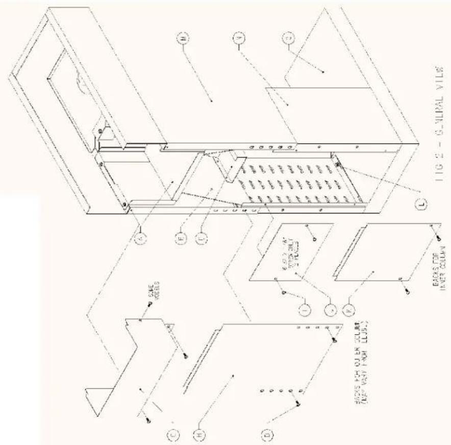
This brewer is equipped with a telescoping column to allow periodic adjustments of brewer heights. This feature allows continued use of the same piece of brewing equipment although the style of dispenser may change over time. The brewer has an inner and outer column which slide up and down opposite of each other. Three functional elements combined together give the telescoped brewer its unique characteristics and strengths.
- A flat "spring" lock (B), secured to the tank shelf, engages detents located internally on both sides of the wrapper and carries the bulk of the brewer's weight.
• Retainer straps (F), secured after height adjustment, prevent the head from lifting.
- Screws (D), which secure the outer back to the column, tie inner and outer column providing additional strength and stability.
TELESCOPING BREWER CHASSIS DIAGRAM

ADJUSTING TELESCOPING BREWER:
-
Perform the following steps in the order outlined prior to attempting brewer adjustment.
-
Disconnect the brewer from its power source.
- Disconnect the brewer from its water source.
-
Allow brewer's hot water tank to cool down.
• For easier height adjustment remove brewer top cover, tank lid, and siphon off water from the tank. -
Remove the lower back (H) from the outer column (M) by removing the two [2] screws (D) near the back's lower edge. Note: These screws secure both columns together, so use caution, as the head assembly will be loose once they are removed.
- Remove the lower back (K) from the inner Column (N). It is not necessary to remove the other two [2] brewer's back panels. (G&J).
- Locate the two [2] brass knurled nuts (E) attached to the retainer straps (F) at the front of the brewer. Loosen the nuts by turning the nuts counter clockwise. DO NOT REMOVE.
- The brew head can now be adjusted up or down depending on its current position. Multiple techniques may be used to raise or lower the brew head so use the one that works best for you.
To RAISE the brew head:
Grasp the outer column (M) from behind with one arm while holding the base (O) in position with the other. Raise the brewer to the appropriate height for your vessel and brew basket combination. The brew head may also be raised by lifting against the bottom of the tank support (A) or by using the handles (C), located on the flat spring, while holding the brewer base in position. Ensure that the flat spring lock (B) fully engages an entire row of detents on each side of the brewer and that the rows are the same height from side to side.
To LOWER the brew head:
Grasp the outer column from behind with one arm for support while squeezing the spring lock's handles (C) together. Lower the brewer to the appropriate height for your vessel and brew basket combination. Ensure that the flat spring lock fully engages an entire row of detents on each side of the brewer and that the rows are the same height from side to side. At the lowest position ensure that the spring lock does not set on the screws that secure the column to the base. (L)
- Slide the knurled nuts (E) to a readily accessible location for future adjustments and tighten them securely.
- Replace the lower back (J) on the inner column.
- Place the outer columns' lower back (H) in position and locate the obround slot that lines up with the hole in the inner column. Secure the back to the columns with the screws previously removed. Check brewer stability.
- Refill tank with water; replace tank lid and brewer's top cover. Reconnect the brewer to water and electrical supply. Follow the brewer's operating setup and calibration instructions if a new brew volume is required.
Note: The screws (I) holding the upper inner back should not normally be removed. If they are removed, they should only be replaced with screws of the same length to avoid interference with internal components during adjustment.
ADDENDUM: Temperature and Volume Adjustment Settings
- Unplug the brewer before removing cover.
- Remove and disconnect the cover, from the brewer, as shown in figures 1, 2, 3, & 4.


- Plug the brewer in, to the power source, allowing it to get up to operating temperature. [Green Ready Light Will Illuminate]
Temperature Adjustment:
- To adjust water temperature simply rotate the thermostat's knob clockwise [+] or counter clockwise [-]. Once the temperature has been adjusted, allow the new setting be reached indicated by the green ready light's illumination. A brew cycle can be run using either a digital, or mercury thermometer, checking the new temperature setting. [Be sure and place a decanter underneath the brew basket before performing this task.] Recommended brewing temperature is 195 degrees Fahrenheit.
Water Volume Adjustment:
- Place a decanter underneath the brew basket. Push the start button to activate the brew cycle. Allow the decanter to fill up and the brew basket to drain completely.
- If the water volume comes up short, increase the time by turning timer's knob clockwise [+].
- If the water volume comes up long, decrease the time by turning timer's knob counter clockwise [-].
- It is recommended to run one more brew cycle double-checking the new brew volume setting.
[Note: Brew cycle can be aborted by turning "Off" the red-lighted rocker switch next to the black momentary switch.]
Once the adjustment(s) have been made, unplug the brewer and re-attached the cover to the brewer. Plug the brewer back in.... set to go.

Wiring Schematics: Thermal & Warmer Models
THERMAL MODELS

flowchart
graph TD
    A["TLN/HEATING ELEMENT"] --> B["VL/BK"]
    B --> C["FILL VALVE"]
    C --> D["CY"]
    D --> E["TANK WARMER"]
    E --> F["WL/BK"]
    F --> G["N"]
    G --> H["L1"]
    H --> I["TERMINAL BLOCK"]
    I --> J["120/240 V BREWERS"]
    J --> K["L2"]
    K --> L["N"]
    L --> M["L1"]
    M --> N["BREWER GROUND"]
    N --> O["120 V POWER CORD"]
    O --> P["CAP W/SPLICE"]
    P --> Q["BRK"]
    Q --> R["RED (ARM) LIGHT"]
    R --> S["CN1 CONTROL BOARD"]
    S --> T["CONTROL BOARD"]
    T --> U["PARTIAL CONNECTIONS DIAGRAM"]
    U --> V["CN2"]
    V --> W["GREEN (READY) LIGHT"]
    W --> X["BL/RD"]
    X --> Y["BY"]
    Y --> Z["WR"]
    Z --> AA["BL/RD"]
    AA --> AB["BY"]
    AB --> AC["WR"]
    AC --> AD["BL/RD"]
    AD --> AE["BY"]
    AE --> AF["WR"]
    AF --> AG["BL/RD"]
    AG --> AH["BY"]
    AH --> AI["WR"]
    AI --> AJ["BL/RD"]
    AJ --> AK["BY"]
    AK --> AL["WR"]
    AL --> AM["BL/RD"]
    AM --> AN["BY"]
    AN --> AO["WR"]
    AO --> AP["BL/RD"]
    AP --> AQ["BY"]
    AQ --> AR["WR"]
    AR --> AS["BL/RD"]
    AS --> AT["BY"]
    AT --> AU["WR"]
    AU --> AV["BL/RD"]
WARMER MODELS
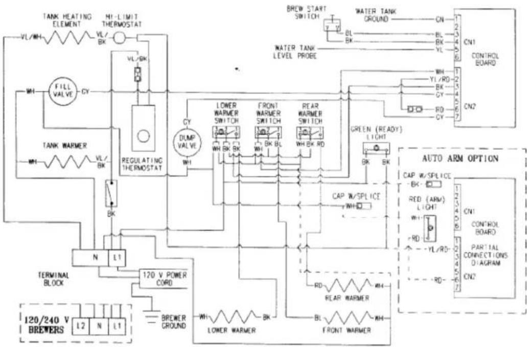
flowchart
graph TD
    A["120/240 V BREWERS"] --> B["L2"]
    B --> C["N"]
    C --> D["L1"]
    D --> E["TANK WARMER"]
    E --> F["WH"]
    F --> G["FILL VALVE"]
    G --> H["CY"]
    H --> I["REGULATING THERMOSTAT"]
    I --> J["CY"]
    J --> K["DUMP VALVE"]
    K --> L["WH"]
    L --> M["L1"]
    M --> N["TERMINAL BLOCK"]
    N --> O["BREWER CROUND"]
    O --> P["WH"]
    P --> Q["L0"]
    Q --> R["LOWER WARMER"]
    R --> S["BK"]
    S --> T["120 V POWER CORD"]
    T --> U["CY"]
    U --> V["LOWER WARMER SWITCH"]
    V --> W["WH BK BK"]
    W --> X["FRONT WARMER SWITCH"]
    X --> Y["WH BK BL"]
    Y --> Z["FLR WARMER SWITCH"]
    Z --> AA["WH BK RD"]
    AA --> AB["GREEN (READY) LIGHT"]
    AB --> AC["BL"]
    AC --> AD["CN1 CONTROL BOARD"]
    AD --> AE["CN1"]
    AF["BREW START SWITCH"] --> AG["7 V"]
    AH["WATER TANK GROUND"] --> AI["CN1"]
    AJ["WATER TANK LEVEL PROBE"] --> AK["BL"]
    AL["CONTROLS"] --> AM["CN1"]
    AN["CONTROLS BOARD"] --> AO["CN1"]
    AP["CONTROLS"] --> AQ["CN1"]
    AR["CONTROLS"] --> AS["CN1"]
ADDENDUM TO OPERATION MANUAL FOR FC BREWERS
The following information is an update to the information manual. It includes changes and enhancements to the features/functions outlined in the operation manual.
The following procedure for filling the water tank with water to its proper operation level.
The brewer needs to be disconnected from the power source.
While depressing the start switch plug machine into the power source. This will fill water tank to the required operating level.
Note: If brewer is powered before depressing the start switch, the water tank will not fill to the proper operating level. If the water probe does not see water within 1 minute, an error light [Auto Arm] will flash.
Other Features:
Auto Cal: Turn timer to the max setting. Push the start switch to start the brew cycle when water is near desired level slowly turn timer back to the left until brewing stops.
Brew Switch: is also a stop switch.
WARRANTY
Applies to all equipment manufactured after 2/1/2017. This warranty supersedes all other previous warranties that are currently in manuals.
• Newco warrants equipment manufactured by it for 1 year parts and labor.
• Accessories and Dispensers 1 Year parts only.
• Electronic Circuit and Control Boards- 3 years parts, 1 year labor.
- Equipment manufactured by others and distributed by Newco- please see original equipment manufacturers warranty, Newco will follow.
These warranty periods run from the date of sale Newco warrants that the equipment manufactured by it will be commercially free of defects in material and workmanship existing at the time of manufacture and appearing within the applicable warranty period. This warranty does not apply to any equipment, component or part that was not manufactured by Newco or that, in Newco's judgment, has been affected by misuse, neglect, alteration, improper installation or operation, relocation or reinstallation, improper maintenance or repair, incorrect voltage applied to the unit at any time, damage or casualty. This warranty does not apply to any equipment failures related to poor water quality, excessive lime and chlorine and non periodic cleaning and descaling. Warranty is null and void if muriatic or any other form of hydrochloric acid is used for cleaning or deliming. In addition, this warranty does not apply to replacement of items subject to normal use including but not limited to user replaceable parts such as faucet seat cups, sight gauge tubes, washers, o-rings, tubing, seals and gaskets.
This warranty is conditioned on the Buyer 1) giving Newco prompt notice of any claim to be made under this warranty by telephone at (800) 556-3926 or by writing to 3650 New Town Blvd, Saint Charles, MO 63301; 2) if requested by Newco, shipping the defective equipment prepaid to an authorized Newco service location; and 3) receiving prior authorization from Newco that the defective equipment is under warranty.
THE FOREGOING WARRANTY IS EXCLUSIVE AND IS IN LIEU OF ANY OTHER WARRANTY, WRITTEN OR ORAL, EXPRESS OR IMPLIED, INCLUDING, BUT NOT LIMITED TO, ANY IMPLIED WARRANTY OF EITHER MERCHANTABILITY OR FITNESS FOR A PARTICULAR PURPOSE. The agents, dealers or employees of Newco are not authorized to make modifications to this warranty or to make additional warranties that are binding on Newco. Accordingly, statements by such individuals, whether oral or written, do not constitute warranties and should not be relied upon.
If Newco determines in its sole discretion that the equipment does not conform to the warranty, Newco, at its exclusive option while the equipment is under warranty, shall either 1) provide at no charge replacement parts and/or labor (during the applicable parts and labor warranty periods specified above) to repair the defective components, provided that this repair is done by a Newco Authorized Service Representative; or 2) shall replace the equipment or refund the purchase price for the equipment.
THE BUYER'S REMEDY AGAINST NEWCO FOR THE BREACH OF ANY OBLIGATION ARISING OUT OF THE SALE OF THIS EQUIPMENT, WHETHER DERIVED FROM WARRANTY OR OTHERWISE, SHALL BE LIMITED, AT NEWCO'S SOLE OPTION AS SPECIFIED HEREIN, TO REPAIR, REPLACEMENT OR REFUND.
In no event shall Newco be liable for any other damage or loss, including, but not limited to, lost profits, lost sales, loss of use of equipment, claims of Buyer's customers, cost of capital, cost of down time, cost of substitute equipment, facilities or services, or any other special, incidental or consequential damages.

NOTES


- Installation/Operation Manual
- FC SERIES BREWERS
- Table of Contents
- PLUMBER'S INSTALLATION INSTRUCTIONS:
- BREWER SET UP PROCEDURES:
- WARNING: READ AND FOLLOW INSTALLATION INSTRUCTIONS BEFORE PLUGGING OR WIRING IN THE BREWER TO AN ELECTRICAL CIRCUIT. WARRANTY WILL BE VOIDED IF BREWER IS CONNECTED TO ANY VOLTAGE OTHER THAN SPECIFIED ON THE SERIAL TAG.
- BREWER SET UP PROCEDURES - CONTINUED:
- COFFEE PREPARATION PROCEDURES:
- Supplement To FC Telescoping Brewer Operation Only:
- TELESCOPING BREWER CHASSIS DIAGRAM
- ADJUSTING TELESCOPING BREWER:
- To RAISE the brew head:
- To LOWER the brew head:
- ADDENDUM: Temperature and Volume Adjustment Settings
- Temperature Adjustment:
- Water Volume Adjustment:
- Wiring Schematics: Thermal & Warmer Models
- ADDENDUM TO OPERATION MANUAL FOR FC BREWERS
- Other Features:
- WARRANTY
Brand : Newco
Model : FC-3
Category : Coffee maker