
Magiglo 540 - Heating Real Flame - Free user manual and instructions
Find the device manual for free Magiglo 540 Real Flame in PDF.


| Product Type | Electric Fireplace |
| Model | Magiglo 540 |
| Brand | Real Flame |
| Width | 540 mm (21.3 in) |
| Height | 580 mm (22.8 in) |
| Depth | 280 mm (11.0 in) |
| Weight | 18 kg (39.7 lb) |
| Power Supply | 220-240 V ~ 50 Hz |
| Power Consumption | 1500 W (heating) |
| Heat Output | Up to 40 m² (430 ft²) |
| Flame Effect | LED with adjustable brightness |
| Thermostat | Adjustable thermostat included |
| Remote Control | Included |
| Safety Features | Overheat protection, cool-touch glass |
| Installation | Built-in or wall-mounted |
| Material | Steel body, glass front |
| Fuel | Electric (no real fuel) |
| Maintenance | Clean glass with damp cloth; replace LED bulbs every 3-5 years |
| Warranty | 2 years |
| Spare Parts Available | Yes (LED modules, remote, glass) |
Frequently Asked Questions - Magiglo 540 Real Flame
User questions about Magiglo 540 Real Flame
0 question about this device. Answer the ones you know or ask your own.
Ask a new question about this device
Download the instructions for your Heating in PDF format for free! Find your manual Magiglo 540 - Real Flame and take your electronic device back in hand. On this page are published all the documents necessary for the use of your device. Magiglo 540 by Real Flame.
USER MANUAL Magiglo 540 Real Flame
natural_image
Technical line drawing of a mechanical assembly with mounting feet and internal components (no text or symbols)MAGIGLO® SERIES
INSTALLATION & OPERATING MANUAL
This Magiglo series of original 320 and 360 decorative fires are suitable to be installed as a type 1 installation into a masonry or approved prefabricated fireplace and are designed to operate with Natural gas only. Approval Number 6094 G
VERSION 17.1
WARRANTY INFORMATION
The benefits provided to you under the following warranty are in addition to any other rights and remedies available to you under the law.
1. Warranty
If:
(a) during the first 15 years from the date of purchase (Firebox Warranty Period), there is a defect in the firebox of the Gas Burner; or
(b) during the first 2 years from the date of purchase (Parts Warranty Period), there is a defect in the gas valves or other parts of the Gas Burner,
due to improper workmanship or material, Glen Dimplex will replace or repair the Gas Burner without charge. Any replacement product is warranted only for the time remaining on the original Firebox Warranty Period or the Parts Warranty Period as relevant.
2. Registration
You must register to receive the benefit of this warranty by completing the warranty registration on our website (www.realflame.com.au) or completing and mailing the attached registration card within 30 days of purchase of your Gas Burner (or, if the Gas Burner is fitted to a new home, within 30 days of the date of settlement of purchase of such new home).
3. Exclusions
Glen Dimplex is not obliged to replace or repair the Gas Burner under clause 1 if:
(a) it has been improperly stored, installed, connected, used, operated or repaired, or damaged, abused, tampered with, altered (without our written approval), or not maintained in strict accordance with our installation and operating instructions; or
(b) it has been installed in an outdoor setting.
4. Limit of Liability
The warranty provided under this warranty is limited to replacement or repair of the Gas Burner only, at our option. To the extent permitted by law, Glen Dimplex excludes liability for consequential loss or any other loss or damage caused to property or persons arising from any cause whatsoever, and damage arising from normal wear and tear.
5. Claiming under the Warranty
In order to claim under this warranty you must, within the Firebox Warranty Period or the Parts Warranty Period (as relevant), contact Glen Dimplex, providing the original proof of purchase and the details below:
Supplier Name
Date Of Purchase / settlement of property if new home ____
Model / Serial Number
This warranty does not cover the cost of claiming under the warranty or transporting the Gas Burner to and from the supplier.
Our goods come with guarantees that cannot be excluded under the Australian Consumer Law. You are entitled to a replacement or refund for a major failure and for compensation for any other reasonably foreseeable loss or damage. You are also entitled to have the goods repaired or replaced if the goods fail to be of acceptable quality and the failure does not amount to a major failure.
If you would like to speak to someone about your Gas Burner or claiming under this warranty, please contact the Service Warranty Desk on 1300 554 155.
Glen Dimplex Australia Pty Ltd ACN 69 118 275 460
Head Office: 1340 Ferntree Gully Road, Scoresby 3179
Telephone: (03) 8706 2000 Facsimile: (03) 876 2001
INSTALLATION NOTICE
The installation of this appliance is only to be carried out by an authorised person in accordance with the Manufacturer's Instructions, local gas fitting regulations, AS/NZS5601.1-2013 installation code for gas burning appliances and any other relevant statutory regulations.
In all cases the installation of this appliance shall meet the requirements as set out in AS/NZS5601.1-2013
NOTE: A slight smell may be apparent for the first few hours of use. This is due to the heat resistant paint curing. It is recommended to open windows in the room for the first lighting of the fire. In some instances a slight discolouration may occur inside the firebox. This is a normal condition and is not covered by warranty.
IMPORTANT SAFETY NOTICES
■ DO NOT PLACE ARTICLES ON OR AGAINST THIS APPLIANCE.
■ DO NOT USE OR STORE FLAMMABLE MATERIAL NEAR THE APPLIANCE.
■ DO NOT SPRAY AEROSOLS IN THE VICINITY OF THIS APPLIANCE WHILST IT IS IN OPERATION.
■ CARE MUST BE TAKEN TO ENSURE THAT ANY RETURN AIR REGISTER OR EXHAUST SYSTEM DOES NOT ADVERSELY AFFECT THE OPERATION OF THE APPLIANCE OR DRAUGHT OF CHIMNEY OR FLUE.
■ DO NOT MODIFY THIS APPLIANCE.
THIS APPLIANCE IS DESIGNED TO OPERATE WITH LUMINOUS FLAMES. THIS MAY EXHIBIT SLIGHT CARBON DEPOSITS.
VENTILATION REQUIREMENTS
Permanent ventilation of the room where the fire is to be situated is essential while fire is in operation. The room must have a minimum cross sectional area of 40,000 sq mm of effective ventilation.
THIS APPLIANCE REQUIRES FRESH AIR TO OPERATE SAFELY. THE ROOM WHERE THIS APPLIANCE IS INSTALLED MUST HAVE PERMANENT VENTILATION FROM OUTDOORS, IN ACCORDANCE WITH THE VENTILATION REQUIREMENTS OF AS/NZS 5601
It is recommended that you service your gas fire every 2 years.
WARNING
This firebox has a naked flame, care should be taken when it is operating if children or the infirm are in close proximity. For protection of young children or the infirm, a secondary guard is required. A safety screen is recommended if constant supervision is not possible. It is recommended that a secondary guard complying with AS-NZS2286 be installed.
The appliance is not intended for use by persons (including children) with reduced physical, sensory or mental capabilities, or lack of experience and knowledge, unless they have been given supervision or instruction concerning use of the appliance by a person responsible for their safety. Children should be supervised to ensure that they do not play with the appliance.
THIS IS PRIMARILY A DECORATIVE APPLIANCE AND IS NOT CERTIFIED AS A SPACE HEATER.
CONTENTS
Contents 4
Data Plate....5
Dimensions....5
Installation Instructions ....6
Lighting Instructions....7
Commissioning Procedure 8
Typical Type 1 Installation to existing chimney ....9
Type 1 Installation into Victorian/Federation grate ....10
Typical Type 2 Installation of Prefabricated Fire Box into existing chimney......11
User Instructions....12
Troubleshooting ....12
Conversion details ....13
Parts List....14
Glen Dimplex contact information ....16
DATA PLATE (Affixed to the base of the unit for reference to gas pressure & consumption)
| BURNER MODEL N | ATURAL GASINJ. SIZE MJ/Hr TPP (kPa) | ||
| 320 2.40 24 0.80 | |||
| 360 2.50 26 0.80 | |||
DIMENSIONS
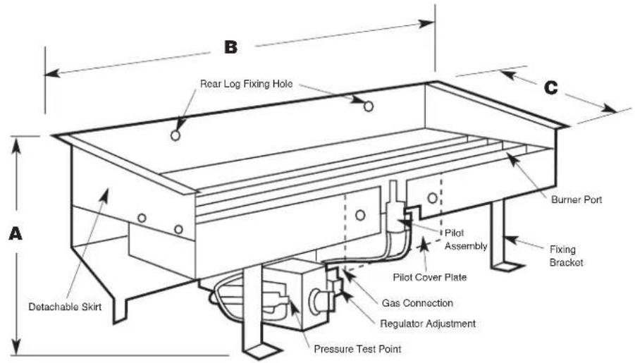
| Model A | B | C |
| 320 165 320 120 | ||
| 360 165 360 120 |
INSTALLATION INSTRUCTIONS
IMPORTANT
This product is fitted with an OXYGEN DEPLETION SYSTEM which is an INTEGRAL PART OF THE PILOT. You must maintain the correct pressure for the oxygen depletion system to operate correctly (see data plate on page 5).
When checking gas pressure at the appliance ALL OTHER GAS APPLIANCES IN PREMISES MUST BE OPERATING AT THE SAME TIME.
Failure to have correct pressure may result in unit cutting out intermittently.
TYPE OF INSTALLATIONS
TYPE 1. Magiglo Gas Log/Coal Set
The appliance must be installed in a fire resistant fireplace with approved draft.
TYPE 2. Magiglo Gas Log/Coal Set
Installed in conjunction with a prefabricated firebox into an existing fireplace using the firebox flue system to remove waste products.
LOCATION REQUIREMENTS FOR TYPE 1 INSTALLATIONS
- The fireplace must be built in accordance with the building regulations for masonry chimneys.
- The fireplace must be sufficiently deep enough to fully accommodate either the Gas Log/Coal Set or a firebox fitted with a Gas Log/Coal Set in order that no fumes can escape into the room. DO NOT ignore the depth of the lintel over the fireplace opening.
- It is imperative that the chimney or flue operates correctly and also does not subject the living area to spillage of combusted products. The flue or chimney should be tested and proven to have an adequate updraught sufficient to remove all waste products of combustion. (Refer to Commissioning Procedure).
- Chimney dampers, baffles or restrictive plates must be removed or permanently fixed open.
- Permanent ventilation of the room where the fire is to be situated is essential while fire is in operation. The room must have a minimum cross sectional area of 40,000 sq mm of effective ventilation.
- Packaging and transit protection must be removed from the appliance prior to installation. This includes pallet, plastic wrap, temporary labels and foam protection.
BURNER INSTALLATION
- Select the Magiglo series burner which best compliments your fireplace size.
- Locate your gas fire into the rear of t grate by location lugs on burner. he fireplace or prefabricated fire box fixing to base or
- It is preferable for the gas line to be brought into the rear of fireplace, therefore concealing pipe work.
- If installing the burner into an existing grate, remove that part of base of grate so that controls are on underside of grate.
- Connect gas line to burner connection using 1/2" flared copper union supplied.
- The correct logs and coals or pebbles must be used as supplied by the manufacturer.
THIS APPLIANCE REQUIRES FRESH AIR TO OPERATE SAFELY. THE ROOM WHERE THIS APPLIANCE IS INSTALLED MUST HAVE PERMANENT VENTILATION FROM OUTDOORS, IN ACCORDANCE WITH THE VENTILATION REQUIREMENTS OF AS/NZS 5601"
FOR YOUR SAFETY READ BEFORE LIGHTING
The appliance has a pilot which must be lit using the piezo ignition, when lighting the pilot follow the instructions exactly.
■ Before lighting the appliance check for gas leaks.
Use only your hand to push in and turn the gas control knob, never use tools. If the knob will not push in or turn by hand, don't try to repair it, call a qualified service technician. Force or attempt to repair may result in a fire or explosion.
If the controls have been underwater, immediately call a qualified service technician to inspect the appliance and replace any part of the control system and fan that has been immersed in water.
LIGHTING INSTRUCTIONS - Magiglo 320 & 360

Figure 1

Figure 2

Figure 3

Figure 4

Figure 5
- To light the pilot, press in and turn the gas control knob anticlockwise to the pilot position.
- Keep knob depressed and turn the knob anticlockwise toward the star until you hear a click. If the pilot lights, continue to depress knob for 20 seconds and release. If pilot goes out repeat the procedure.
- To light the burner, turn the control knob to the flame setting. The burner can be set anywhere between low and high flame.
- To turn the burner off, turn the control knob clockwise to the "PILOT" position. This will leave the pilot burning.
- To turn off the burner and the pilot, turn the knob clockwise to the "OFF" position.
If you are unable to get the appliance to operate correctly, contact either your sales agent or the manufacturer (see contact details on b ack cover).
Test operation of appliance and fully instruct user before leaving.
Note: Check gas pressure. Refer to Data Plate on page 4 for details.
TO TURN OFF GAS TO APPLIANCE
Push in gas control knob slightly and turn to the "OFF" position.
COMMISSIONING PROCEDURE
Once the fire is installed and operational the installer must check for spillage. Carry out the lighting procedure and turn the fire to high. Allow to warm up for 10 minutes and then using a smoke match set 25mm down and 25mm inside of the fire opening run the match across the width of the opening to check that all of the smoke is drawn away.
Repeat the test with doors and windows to the premises open and closed, and with any extractor fans in the same room or adjacent rooms running on high. The fire should continue to clear its combustion products. Also operate any other flued appliances in the same or neighbouring rooms and ensure they continue to function satisfactorily as multiple flues can work against one another.
If spillage is detected during this procedure it could indicate a faulty flue or lack or ventilation. If the problem cannot be rectified immediately, disconnect the appliance, and advise the customer not to use the appliance until the problem has been resolved.
The customer should always be advised of the need for regular servicing and checks to ensure the continued clearance of combustion waste products.
NOTE: Care must be taken to ensure that any return air register exhaust system does not adversely affect the operation of the appliance or draught of chimney or flue.
WARNING
“DO NOT place articles on or against this appliance.”
“DO NOT use or store flammable materials near this appliance.”
“DO NOT spray aerosols in the vicinity of this appliance while it is in operation.
TYPICAL TYPE 1 INSTALLATION TO EXISTING CHIMNEY

TYPE 1 INSTALLATION INTO VICTORIAN/FEDERATION GRATE
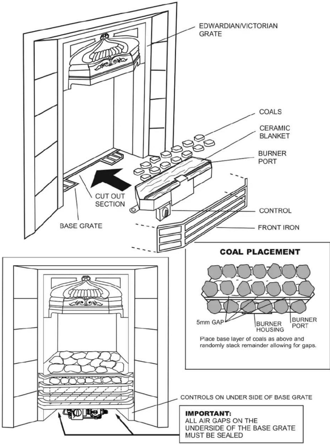
• Minimum insert depth 180mm.
• Maximum insert opening 675mm.
USER INSTRUCTIONS
- Your Magiglo Gas Log/Coal Set will have been installed by an authorised person in accordance with the Installation and Service Instructions. If you are technically minded you will increase your knowledge of your fire by reading through these Instructions
- Initially your Magiglo may burn with a slightly blue flame which part of the protective coating on the coal and logs burn off. A slight smell my also be apparent at this stage. After an hour or so the fire will have settled down and will therefore burn with a yellow flame producing a little soot. The soot deposit enhances the real effect and is exactly the same as an authentic fire.
- As with all gas appliances, your Magiglo should be regularly serviced. We would recommend once each year. The name and address of your service technician can be obtained from your Real Flame stockist. The routine to be followed by the engineer can be found under Service Instructions; contained within this leaflet.
- For safe operation of your Magiglo the following annual checks should be carried out.
- Confirm that the chimney remains clear and unobstructed and there has not been a build-up of soot which would necessitate the chimney being swept.
- Confirm that the room ventilation remains adequate and that all vents are free of obstruction.
TROUBLESHOOTING
| Symptom | Corrective Action |
| Pilot won’t light | 1. Pressure too low. Set to correct pressure.2. Check for spark at electrode if none, check lead connection. If not solved replace electrode. |
| Pilot lights but does not stay on. | Light pilot and keep knob depressed for 30 seconds before releasing. If pilot does not stay on, replace thermocouple. |
| Main flame goes out or very little flame. | 1. Check for correct pressure.2. Check for faulty thermocouple.3. Excessive draught can cause flame to extinguish. |
WARNING
The Magiglo burner burns with a real flame which should be treated with the same respect as any naked flame. A fireguard should be used for the protection of children and the elderly.
CONVERSION DETAILS
APPLIANCE AVAILABLE IN NATURAL GAS ONLY
PARTS LIST
| PART No. | DESCRIPTION PART No. | ||
| 01 | Negabhan Control Valve | 05 1/2" to 3/8" Hex Nipple | |
| 02 | Regulator | 06 5/16" 90O Union Elbow | |
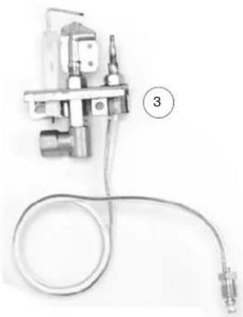
| 03N | S.I.T. ODS Pilot Assembly (Natural Gas) | 07 1/4" Nut and Olive | |
| 03P | S.I.T. ODS Pilot Assembly (Propane Gas) | 08 Injector Holder Stem | |
| 04 | 1/2" Male to 1/2" Copper Union | 09 Injector | |
natural_image
Mechanical component with coiled cable and labeled part (3), no visible text or symbolsMagiglo 320 & 360

6

7 8

5

2

4
COAL SET

natural_image
Close-up of several dark, irregularly shaped objects on a white background (no text or symbols visible)
www.realflame.com.au
1300 554 155
- MAGIGLO® SERIES
- INSTALLATION & OPERATING MANUAL
- WARRANTY INFORMATION
- Warranty
- Registration
- Exclusions
- Limit of Liability
- Claiming under the Warranty
- INSTALLATION NOTICE
- IMPORTANT SAFETY NOTICES
- VENTILATION REQUIREMENTS
- WARNING
- CONTENTS
- DATA PLATE (Affixed to the base of the unit for reference to gas pressure & consumption)
- INSTALLATION INSTRUCTIONS
- IMPORTANT
- TYPE OF INSTALLATIONS
- TYPE 1. Magiglo Gas Log/Coal Set
- TYPE 2. Magiglo Gas Log/Coal Set
- LOCATION REQUIREMENTS FOR TYPE 1 INSTALLATIONS
- BURNER INSTALLATION
- FOR YOUR SAFETY READ BEFORE LIGHTING
- LIGHTING INSTRUCTIONS - Magiglo 320 & 360
- TO TURN OFF GAS TO APPLIANCE
- COMMISSIONING PROCEDURE
- USER INSTRUCTIONS
- TROUBLESHOOTING
- CONVERSION DETAILS
- PARTS LIST
- COAL SET
Brand : Real Flame
Model : Magiglo 540
Category : Heating