
AC-MANAGE - Mobile Device Charger Anywhere Cart - Free user manual and instructions
Find the device manual for free AC-MANAGE Anywhere Cart in PDF.


| Product Type | Mobile Device Charger |
| Model | AC-MANAGE |
| Brand | Anywhere Cart |
| Dimensions (L x W x H) | 3.5 x 2.0 x 1.0 inches |
| Weight | 3.2 oz (91 g) |
| Input Voltage | 100-240 V AC, 50/60 Hz |
| Output Power | 5V/2.4A per port (max 4.8A total) |
| Number of Charging Ports | 2 USB-A ports |
| Charging Technology | Smart charging with device detection |
| Compatible Devices | Smartphones, tablets, Bluetooth headphones, and other USB devices |
| Safety Features | Overcurrent, overvoltage, short circuit, and overheat protection |
| Material | Fire-retardant ABS plastic |
| Certifications | FCC, CE, RoHS |
| Operating Temperature | 32°F to 104°F (0°C to 40°C) |
| Cable Included | No (USB cables sold separately) |
| Maintenance | Wipe with dry cloth; unplug during storms |
| Repairability | Non-repairable; contact customer support for replacement |
| Warranty | 1 year limited warranty |
| Package Contents | Charger unit, user manual |
Frequently Asked Questions - AC-MANAGE Anywhere Cart
User questions about AC-MANAGE Anywhere Cart
0 question about this device. Answer the ones you know or ask your own.
Ask a new question about this device
Download the instructions for your Mobile Device Charger in PDF format for free! Find your manual AC-MANAGE - Anywhere Cart and take your electronic device back in hand. On this page are published all the documents necessary for the use of your device. AC-MANAGE by Anywhere Cart.
USER MANUAL AC-MANAGE Anywhere Cart
Thank you for choosing Anywhere Cart!
The AC-MANAGE is designed to charge and store 1-36 Chromebooks and laptops, plus a networking switch for wired management using CAT-5, 5e or 6 cables. Adjustable device divider bays allow fitment of any width device in 1/2" increments.
Please review this manual before installing your equipment to learn how to safely use your cart.
AC input: 120V AC 60 Hz
Max amps: 15A
Max wattage: 1875W
Identifying Components

Front of Cart (closed)
- Locking Removable Network Switch Panel
- Push Handles
- Door Lock Latch w/Padlock Flange
- 5" Swivel / Brake Lock Casters (2)
- 5" Swivel / Directional Lock Casters (2)

natural_image
Interior view of a multi-level electronic device chassis with numbered compartments (6, 7, 8, 9) and wheels (no visible text or symbols)Front of Cart (open)
- CAT-5/6 Patch Thru Ports
- Cord Pass-Through Slots
- Adjustable Dividers
- Lower Bumpers

Back of Cart (open)
- External Pass-Through
- Network Host Port
- External Power Switch
- AC Adapter Baskets
- Power Outlet Strips
- INTELLI-SENSE Charger
- In-line GFCI Circuit


Model:
Serial Number:
Charging System:
Date Of Purchase:
Reseller Name:
Customer ID:
Installing Handles & Bumper Option
-
Open the front of the cart and remove the cardboard box containing the handles. Locate the threaded bolts.
-
Using the supplied hex key, install both handles. Do not overtighten bolts.

natural_image
Metal rod with flanged ends and mounting holes (no text or symbols)
natural_image
Exterior view of a white cabinet or enclosure with ventilation grilles and mounting holes (no text or symbols visible)
natural_image
Close-up of a black mechanical lever mounted on a white industrial device (no visible text or symbols)-
Locate the bumper kit and bolts.
-
Using the supplied hex key and threaded bolts, install bumpers on corners.

natural_image
Close-up of a white industrial cart with visible wheels and wiring (no text or symbols)
natural_image
Close-up of a white industrial cart with four wheels and black control knobs (no visible text or symbols)Removing the Top Panel
Your cart is equipped with a removable top panel for storing a standard height 1u Ethernet switch. The mounting system for the switch is adjustable for various lengths and can be powered via the internal electrical outlet.
Start by unlocking the top panel. With an assistant, pull the top toward you first, then lift up. The panel is quite heavy, so take extra care not to drop it, setting it aside in a way that doesn't cause it to fall.

natural_image
Exterior view of a modern office building (no signage)
natural_image
Exterior view of a modern office building (no signage)Identifying Components Under Top Panel
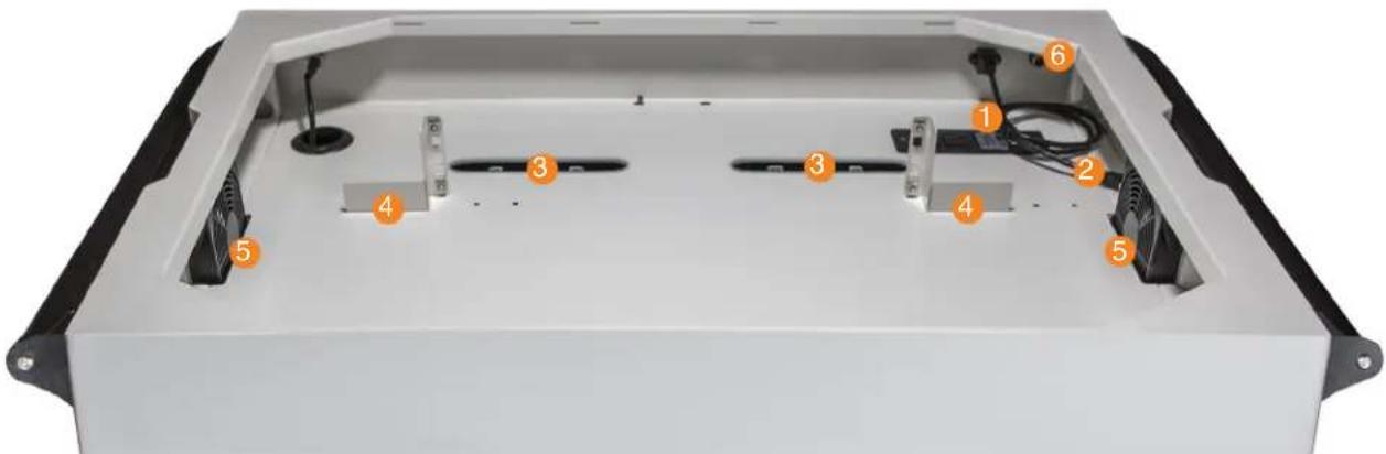
- Electrical Outlet
- Network Host Port Cable
-
Cord Pass-Through Slots
-
1u Network Switch Mounting Brackets
- Cooling Fans
- External Pass-Through Hole
Setting Up Your Network Switch
If your Network Switch is equipped with rack ears, loosen the mounting bracket screws using a phillips head screwdriver. Align the mounting brackets with the overall length of the switch. You may have to loosen the brackets and use additional mounting holes to gain the correct width.
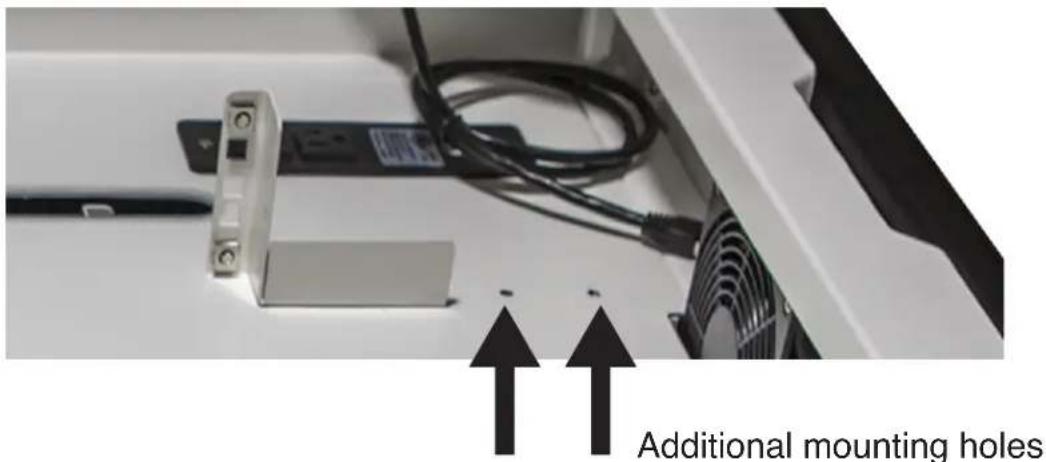
Your cart is equipped with CAT 5/6 Patch Thru Ports above each device space. This alleviates the use of extra long cables directly from the Network Switch. Follow the instructions supplied by your Network Switch manufacturer.

Understanding Caster Positions
Your cart may be equipped with Casters that have an "Orange" color foot pedal.
By engaging this Directional Locking Caster (Pressing the foot pedal down), your cart will easily track in a straight line. This makes pushing the cart down a hallway or around campus more efficient.
By releasing the Direction Lock (Lifting up on the foot pedal), the cart will have its full swivel motion, making parking the cart in a tight corner easy.
Directional Locking

natural_image
Black and silver bicycle steering wheel with orange bidirectional arrow indicating left and right motion (no text or symbols)Full Swivel

natural_image
Black and white photo of a black three-wheeled vehicle with orange exhaust platters (no text or symbols)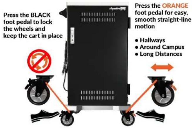

Setting Up Your Devices (Front)
Device slots come set at 1" wide and are adjustable in 1/2" increments.
- Using a ruler, measure the thickest part of your device. If it is less than 1" thick, skip to next page.

natural_image
Exterior view of a modern laptop with a golden ruler beside it (no visible text or symbols)- Slide Retaining Strip forward & out of the way. Strip can be removed.

natural_image
Close-up of a hand holding a white plastic clip against a dark background (no text or symbols visible)- Adjust spacing as needed in 1/2" increments.

natural_image
Hand inserting a black plastic electrical connector into an open electrical cabinet (no visible text or symbols)- If your device is thicker than 1", locate & remove thumbscrew by turning counter clockwise.

natural_image
Close-up of a hand holding a white plastic panel with black metal clamps, no visible text or symbols- Pulling forward, then up, remove divider panel.

natural_image
Close-up of a hand adjusting black mechanical components on a grid-patterned surface (no text or symbols visible)- Slide retaining metal strip into place & replace thumbscrew.

natural_image
Close-up of a hand adjusting black plastic heat exchangers on a server rack (no visible text or symbols)Setting Up Your Devices (Back)
- Remove baskets by pulling forward, then upward.

natural_image
Interior view of an industrial control cabinet with visible wiring and a control panel (no text or symbols)- Hook baskets back in place & plug power cables into outlets.

natural_image
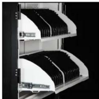
Close-up of a mechanical device with perforated plate and control panel (no visible text or symbols)- Working up front, slide front shelves out.
natural_image
Close-up of server rack-mounted drive bays with black modules (no visible text or labels)- Use the supplied Cable Clips to fasten each cable to the divider by pressing down, securing the cable in place.

natural_image
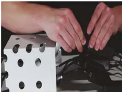
3D diagram of a black plastic component with internal slots and two red arrows pointing to features (no text or symbols)- Separate AC adapters from power cords, place "brick" into basket and feed cords through bottom holes.
natural_image
Close-up of hands assembling a white die with circular holes, next to a black plastic component (no visible text or symbols)- Feed device cables into pass-thru slots to front of cart.

natural_image
Close-up of hands holding black plastic clips with wires, no visible text or symbols- Weave device cables into divider tabs.

natural_image
Close-up of a hand adjusting black plastic clips on a rack (no visible text or symbols)Turning The Charging System ON
- Plug power cord into outlet.

natural_image
Hand inserting a black plug into an electrical outlet (no text or symbols visible)- Press the 'External Power Switch' located on the back side and switch will illuminate green.

natural_image
Interior view of a white industrial machine with multiple battery modules and wiring, showing a close-up of a hand interacting with a circular device (no text or symbols visible)SMART CHARGING SYSTEM

The AC-PRO-II is equipped with the INTELLI-SENSE Smart Charging System. Its designed to more efficiently charge your devices while also creating a plug and play environment.

Within 5 seconds of plugging in your cart's power cord, your INTELLI-SENSE Smart Charging System will initiate an test of your devices charging level requirements. Devices which are plugged into power strips that draw the most power will take priority and can take up to 2 hours before switching to the next set of outlets. Once devices are fully charged, the system will remain in a trickle charging state, maintaining your devices battery levels.
If you prefer, a 30 Minute Cycle Mode is available by switching the Mode Selection Switch to the LEFT. This will start to charge devices which are on the "A" circuit. After 30 minutes, devices which are on the "B" circuit will charge. This continuous cycle will remain in operation until your cart's External Illuminated LED Power Button is pressed and no longer illuminates.
- Power Cord Inlet
- Internal Power Button
- Mode Selection Switch
- External Switch Cable
- LED Indicators
ELECTRICAL TROUBLESHOOTING
IDENTIFYING COMPONENTS
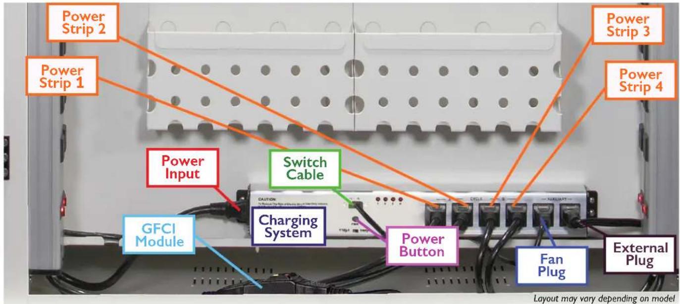
Step 1: Testing the GFCI Module
- With your cart plugged in, open the rear panel door.
- Locate the GFCI Module on the left side bottom of your cart.
- Press down on the Yellow Button (Test).
- Then press the Red Button (Reset).
- Allow 5 seconds for the Charging System to reset.
- If resetting the GFCI Module did not correct the issue, go to Step 2.
Part # 1322859

natural_image
Close-up of hands pointing at a red button on a black electronic device (no visible text or symbols)Step 2: Testing the Power Cord
- Unplug your cart and remove cords from both ends of the GFCI Module.
- Plug the main Power Cord into the Power Input port located on the left side of the Charging System.
- Plug the cart back into a wall outlet and press the internal Power Button labeled PWR on the Charging System.
- If the system does not power on, verify that your Power Cord is not damaged by plugging in a PC monitor style IEC-320-C13 Power Cord.
- If the system powers on, replace the Power Cord, otherwise go to Step 5.
Part # 1320399

Step 3: Testing the Power Strips
- Open the rear panel door and locate the 4 vertically mounted Power Strips.
- Verify each switch is in the "RESET" position, not the "OFF" position.
- Using an extension cord, test each Power Strip by unplugging each cord from the charging system and plugging them into the extension cord.
- If one or more Power Strips no longer works, replace as needed.

natural_image
Two identical electrical outlet cables with indicator lights and power socket switches (no text or symbols visible)10 Outlet Power Strip Right Side, 22" cord
10 Outlet Power Strip Left Side, 14" cord
Part # 1321770
Part # 1320938
ELECTRICAL TROUBLESHOOTING
Step 4: Testing the External Power Button
Part # 1321375
- With your cart plugged in, open the rear panel door and press the internal Power Button labeled PWR on the charging system.
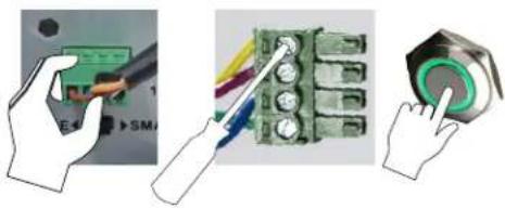
- If your cart powers on, unplug the Switch Cable from the Charging System.
- Using a small flat head screwdriver, ensure all individual wires are secure.
- Plug the Switch Cable back into the Charging System then press the External Power Button on the side of your cart.
- If the External Power Button does not light up or power on, replace it.
natural_image
Three-step diagram showing hands installing a circuit board with a power connector and a tape measure (no text or symbols present)Step 5: Determining your Model Number
- Find the model name and serial number sticker. This sticker may be on the side or back.
- Determine which Charging System is installed by opening the back door / panel.
Model and Serial Number
Sticker Location

Step 6: Testing the Charging System
Intelli-Sense Smart Charging System
Part # 1323152

- Remove all plugs from the outlets of your Charging System.
- Power on your system by pressing the internal Power Button.
- Verify the "1" and "2" LEDs illuminate for about 10 seconds.
- Verify the "3" and "4" LEDs illuminate for about 10 seconds.
- Finally, verify all four LEDs illuminate for about 10 seconds.
- If this sequence does not occur, replace the Charging System.

flowchart
graph LR
    A["10 Sec"] --> B["10 Sec"]
    B --> C["10 Sec"]
LIMITED WARRANTY
- The terms below shall have the following definitions for purposes of this Warranty:
"Client" means the original party purchasing the Products from Anywhere Cart or from an authorized dealer to sell Anywhere Cart branded products.
"Components" mean the mechanical components of a Product including the wheels, locks, drawer slides and hinges.
"Electronics" mean the electronic timer, Sync station and power strips. Cords and switches are not warranted.
"Frame" means the main frame or chassis of a Product.
"Products" means any goods and any related services to be supplied by Anywhere Cart to the Client pursuant to the Acceptance of an Order and any other goods or services which Anywhere Cart supplies to the Client from time to time.
Anywhere Cart warrants that the Products to be supplied to Client are free from defects in material and workmanship under normal use and service for which they were intended if, but only if, the Products have been properly installed and operated. Anywhere Cart's obligation under this Warranty is limited to only supplying replacement part(s) for any part(s) which are returned and found to be defective, provided that such part(s) are returned to Anywhere Cart within the following Warranty Period:
a. With regard to the Frame, the Warranty Period shall be for the life of the Product to Client.
b. With regard to Components, the Warranty Period shall be for a period of two (2) years from the date of delivery of the Product to Client.
c. With regard to Electronics, the Warranty Period shall be for a period of two (2) years from the date of delivery of the Product to Client.
Except as prohibited or limited by applicable law, Anywhere Cart does not warrant that the Products meet the requirements of any safely code of any country, state, municipality, or other jurisdiction, and Client assumes all risk and liability whatsoever resulting from the use thereof, whether used singly or in combination with other machines or apparatus. This Warranty shall not apply to any of Anywhere Cart's Products, or parts thereof, which have been repaired or altered, without Anywhere Cart's written consent, outside Anywhere Cart's facility or altered in any way so as, in the sole judgment of Anywhere Cart, to adversely affect the stability or reliability of the Products, or if such Products have been subject to misuse, negligence, or accident, or have been operated in a manner not in accordance with Anywhere Cart's printed instructions or have been operated under conditions more severe than, or otherwise exceeding, those set forth in the specifications for such Products.
EXCEPT AS PROHIBITED OR LIMITED BY APPLICABLE LAW, THIS WARRANTY AND THE OBLIGATIONS AND LIABILITIES OF Anywhere Cart ARE EXCLUSIVE AND IN LIEU OF WARRANTIES, GUARANTIES OR LIABILITIES, EXPRESS OR IMPLIED, INCLUDING ANY IMPLIED WARRANTY FOR MERCHANTABILITY, FITNESS FOR A PARTICULAR PURPOSE, ARISING BY LAW OR OTHERWISE OR WHETHER OR NOT OCCASIONED BY Anywhere Cart's NEGLIGENCE AND CLIENT HEREBY WAIVES ALL REMEDIES NOT EXPRESSLY PROVIDED IN THIS WARRANTY. THIS WARRANTY SHALL NOT BE EXTENDED, ALTERED OR VARIED EXCEPT BY A WRITTEN INSTRUMENT SIGNED BY Anywhere Cart AND CLIENT. REGARDLESS OF THE FAILURE OF THE SOLE AND EXCLUSIVE REMEDIES PROVIDED IN THIS WARRANTY, Anywhere Cart WILL NOT BE LIABLE FOR ANY SPECIAL, INCIDENTAL, INDIRECT OR CONSEQUENTIAL DAMAGES WHATSOEVER (INCLUDING, WITHOUT LIMITATION, DAMAGES FOR LOSS OF REVENUE, BUSINESS OR PROFITS, LOSS RESULTING FROM BUSINESS INTERRUPTION, LOSS OF BUSINESS INFORMATION, LOSS RESULTING FROM ANY CLAIM BY ANY THIRD PARTY, ANY LOSS DUE TO DAMAGE TO PROPERTY, AND INJURY TO OR DEATH OF ANY PERSONS RESULTING, DIRECTLY OR INDIRECTLY, FROM THE USE OR LOSS OF THE PRODUCTS OR ANY OTHER PECUNIARY LOSS) OF ANY KIND OR NATURE. Anywhere Cart NEITHER ASSUMES NOR AUTHORIZES ANY PERSON TO ASSUME FOR IT ANY OTHER LIABILITY IN CONNECTION WITH THE SALE OR USE OF THE PRODUCTS, AND THERE ARE NO ORAL AGREEMENTS OR WARRANTIES COLLATERAL TO OR AFFECTING THIS WARRANTY. THE EXCLUSION OF SPECIAL, INCIDENTAL, INDIRECT OR CONSEQUENTIAL DAMAGES IS AN INDEPENDENT AGREEMENT OF Anywhere Cart AND CLIENT APART FROM THE SOLE AND EXCLUSIVE REMEDIES PROVIDED IN THIS WARRANTY.
Client shall notify Anywhere Cart by registered or certified mail, return receipt requested, of a breach of this Warranty within thirty (30) days after discovery thereof, but not later than the expiration of the applicable Warranty Period, otherwise such claims shall be deemed waived.
- Limitations of Warranty.
Anywhere Cart makes no warranties to any third party. You are responsible for all claims, damages, settlements, expenses, and attorneys' fees with respect to claims made against You as a result of Your use or misuse of the Product. This warranty applies only if the Product is installed, operated, maintained, and used in accordance with Anywhere Cart specifications. Specifically, the warranties do not extend to any failure caused by (i) accident, unusual physical, electrical, or electromagnetic stress, neglect or misuse, (ii) fluctuations in electrical power beyond Anywhere Cart specifications, (iii) use of the Product with any accessories or options not furnished by Anywhere Cart or its authorized agents, or (iv) installation, alteration, or repair of the Product by anyone other than Anywhere Cart or its authorized agents.
- Disclaimer of Warranty.
Except As Expressly Provided Otherwise Herein And To The Maximum Extent Permitted By Applicable Law, Anywhere Cart Disclaims All Other Warranties With Respect To The Product, Whether Express, Implied, Statutory Or Otherwise, Including Without Limitation, Satisfactory Quality, Course Of Dealing, Trade Usage Or Practice Or The Implied Warranties Of Merchantability, Fitness For A Particular Purpose Or Noninfringement Of Third Party Rights.
- Limitation of Liability.
In no event shall Anywhere Cart be liable for indirect, incidental, special, exemplary, punitive, or consequential damages of any nature including, but not limited to, loss of profits, data, revenue, production, or use, business interruption, or procurement of substitute goods or services arising out of or in connection with this limited warranty, or the use or performance of any product, whether based on contract or tort, including negligence, or any other legal theory, even if Anywhere Cart has advised of the possibility of such damages. Anywhere Cart's total, aggregate liability for damages of any nature, regardless of form of action, shall in no event exceed the amount paid by you to Anywhere Cart for the specific product upon which liability is based.
- Governing Law and Your Rights.
This warranty gives You specific legal rights; You may also have other rights granted under state law. These rights vary from state to state.
- Warranty Period for Anywhere Cart Product Purchased:
AC-MANAGE Lifetime Frame, 2 Years Components, 2 Year Electronics
- Thank you for choosing Anywhere Cart!
- Identifying Components
- Front of Cart (closed)
- Front of Cart (open)
- Back of Cart (open)
- Installing Handles & Bumper Option
- Removing the Top Panel
- Setting Up Your Network Switch
- Understanding Caster Positions
- Setting Up Your Devices (Front)
- Device slots come set at 1" wide and are adjustable in 1/2" increments.
- Setting Up Your Devices (Back)
- Turning The Charging System ON
- SMART CHARGING SYSTEM
- ELECTRICAL TROUBLESHOOTING
- Step 1: Testing the GFCI Module
- Step 2: Testing the Power Cord
- Step 3: Testing the Power Strips
- Step 4: Testing the External Power Button
- Step 5: Determining your Model Number
- Step 6: Testing the Charging System
- LIMITED WARRANTY
Brand : Anywhere Cart
Model : AC-MANAGE
Category : Mobile Device Charger