
EG-UPSO-6000 - Inverter EnerGenie - Free user manual and instructions
Find the device manual for free EG-UPSO-6000 EnerGenie in PDF.


| Product Type | Line-Interactive UPS |
| Model | EG-UPSO-6000 |
| Brand | EnerGenie |
| Capacity (VA) | 6000 VA |
| Capacity (Watts) | 3600 W |
| Input Voltage | 220-240 VAC |
| Output Voltage | 220-240 VAC (regulated) |
| Frequency | 50/60 Hz (auto-sensing) |
| Waveform | Pure Sine Wave |
| Transfer Time | 2-6 ms typical |
| Battery Type | Sealed Lead-Acid (maintenance-free) |
| Battery Quantity | 20 x 12V / 9Ah |
| Typical Backup Time | 10-15 minutes at full load |
| Recharge Time | 4-6 hours to 90% |
| Outlets | 8 x IEC 320 C13 + 2 x IEC 320 C19 |
| Communication Ports | USB, RS-232, RJ45 |
| Display | LCD panel with status indicators |
| Dimensions (W x D x H) | 430 x 640 x 175 mm |
| Weight | 62 kg |
| Operating Temperature | 0°C to 40°C |
| Noise Level | <45 dBA |
| Safety Certifications | CE, TÜV, IEC 62040 |
| Warranty | 2 years (battery 1 year) |
Frequently Asked Questions - EG-UPSO-6000 EnerGenie
User questions about EG-UPSO-6000 EnerGenie
0 question about this device. Answer the ones you know or ask your own.
Ask a new question about this device
Download the instructions for your Inverter in PDF format for free! Find your manual EG-UPSO-6000 - EnerGenie and take your electronic device back in hand. On this page are published all the documents necessary for the use of your device. EG-UPSO-6000 by EnerGenie.
USER MANUAL EG-UPSO-6000 EnerGenie
EG-UPSO-6000 EG-UPSO-10000
ONLINE UPS, 6000/10000 VA, USB + SNMP SLOT ONLINE-UPS, 6000/10000 VA, USB + SNMP-STECKPLATZ ONLINE UPS, 6000/10000 VA, USB + SNMP SLOT UPSONLINE, 6000/10000 VA, RANURA USB + SNMP UPS ONLINE, 6000/10000 VA, SLOT USB + SNMP UPS ONLINE, 6000/10000 VA, USB + SLOT SNMP ONDULEUR UPS, 6000/10000 VA, PORT USB + SNMP ONLINE UPS, 6000/10000 VA, USB + SNMP SLOT ONLINE UPS, 6000/10000 VA, GNIAZDO USB + SNMP ОНЛАЙН UPS, 6000/10000 BA, USB + SNMP CLOT TIEŠSAISTES UPS, 6000/10000 VA, USB + SNMP SLOTS UPS ONLINE, 6000/10000 VA, SLOT USB + SNMP
Table of Contents
Important Safety Instructions....3
1 Product Description....4
1.1 Features....5
1.2Models....5
1.3 Appearance....5
1.4System Description....7
1.5UPS Working Mode....8
1.6Product Specifications....11
2 Installation....13
2.1 Unpacking and Inspection....13
2.2Connect Input/Output Power....13
2.3 Operating Procedure for Connecting the Long Backup Time Model UPS with the External Battery....15
2.4Connect Parallel Cables....15
2.5Connect Communication Cables....16
3 Controls and Indicators....18
4 Operation....25
4.1Operation Mode....25
4.2Parallel Operation....25
4.3 Maintenance Bypass Operation Mode....25
5 Communication....26
5.1RS232 and USBPort....26
5.2EPO Port....26
5.3 Intelligent Cards (Optional)....27
6 Maintenance....30
6.1Battery Maintenance....30
6.2Battery Disposal....30
6.3Battery Replacement Procedures....31
6.4Precaution....31
6.5Checking UPS Status....31
7 Troubleshooting....32
Annex A Parallel Setting....36
Annex B Mechanical Size....37
Annex C Battery Run Time....40
Software Download & Installation....40
GENERAL INFORMATION......41
Important Safety Instructions
Save these instructions
This manual contains important safety instructions. Read all safety and operating instructions before operating the uninterruptible power systems (UPS). Adhere to all warnings on the unit and in this manual. Follow all operating and user instructions. This equipment can be operated by individuals without previous training.
This product designed for commercial/industrial use only. It is intended for use with lift support and other designated “critical” devices. Maximum load must not exceed that shown on the UPS rating label. The UPS is designed for data processing equipment. If uncertain, consult your dealer or local representative.
This UPS is designed for use on a properly grounded (earthed), 220/230/240Vac, 50 or 60Hz supply. The factory default setting is 220Vac/50Hz. Installation instructions and warning notices are in this manual.
The UPS 06 -20 kVA@220/230/240Vac is designed for use with a three-wire input (L,N,G).
WARNING
The battery can present a risk of electrical shock and high short circuit current. Following precautions should be observed before replacing the battery.
● Wear rubber gloves and boots.
- Remove rings, watches and other metal objects.
- Use tools with insulated handles.
- Do not lay tools or other metal objects on the batteries.
- Do not dispose of batteries in a fire. The batteries may explode.
- If the battery is damaged in any way or shows signs of leakage, contact your local representative immediately.
● Handle, transport and recycle batteries in accordance with local representative.

WARNING
Although the UPS has been designed and manufactured to ensure personal safety, improper use can result in electrical shock or fire. To ensure safety, observe the following precautions:
● Turn off and unplug the UPS before cleaning it.
- Clean the UPS with a dry cloth. Do not use liquid or aerosol cleaners.
- Never block or insert any objects into the ventilation holes or other openings of the UPS.
- Do not place the UPS power cord where it might be damaged
1 Product Description
Congratulations on your choice of the UPS uninterruptible power system(UPS), the UPS comes in nominal power ratings of 6-20kVA. It is designed to provide conditioned power to computers and other sensitive electronic equipment.
This chapter gives a brief description of the UPS, including the UPS features, models, appearance, operating principle and specification.
NOTICE:
Operated the UPS in an indoor environment only in an ambient temperature range of 0-40°C (32-104°F). Install it in a clean environment, free from moisture, flammable liquids, gases and corrosive substance.
This UPS contains no user-serviceable parts except the internal battery pack. The UPS "push buttons do not electrically isolate internal parts. Under no circumstance attempt to gain access internally, due to the risk of electric shock or burn.
Do not continue to use the UPS if the panel indications are not in accordance with these operating Instructions or the UPS performance alters in use. Refer all faults to your dealer.
Servicing of batteries should be performed or supervised by personnel knowledgeable of batteries and the precautions. Keep unauthorized personnel away from the batteries. Proper disposal of batteries is required. Refer to your local laws and regulations for disposal requirement.
DO NOT CONNECT equipment that could overload the UPS or demand surge current from the UPS, for example: electric drills, vacuum cleaners, hair dryer, motors and so on.
DO NOT CONNECT equipment that is life related, for example: medical equipment, elevator and so on.
Storing magnetic media on top of the UPS may result in data loss or corruption.
Turn off and isolate the UPS before cleaning it. Use only a soft cloth, never liquid or aerosol cleaners.
1.1 Features
The UPS features include:
✿ Providing more highly efficient AC power, compared with the previous generation
Full digital control technology based on DSP to achieve high reliability and power function
✿ Fan speed can be auto conditioned according to the loads, input voltage or working mode
◆ Digitally controlled charger current and voltage, compared with the previous generation which is fixed in hardware
✨ Super high-power density
1.2 Models
Available models are shown as Table1-1:
Table 1-1: Models
| Model Nominal Power Type | |
| EG-UPSO-6000 6kVA/6kW | Online UPS |
| EG-UPSO-10000 10kVA/10kW |
1.3 Appearance

Fig 1-1: Front View
Fig 1-2
: Rear View
As shown in Fig 1-2, the rear panel provides the following components and functions:
RS232: DB9 type, used to connect monitoring software
2 EPO: OFF
3 Parallel port: option
4 USB: B type, used to connect monitoring software
5 Battery temperature option
6 SNMP
Reserved: reserved for customer function, such as manual bypass, battery breaker, socket and so on
8 Fans: intelligent fan speed control
9 Bypass breaker: surge proection
10 Input breaker: surge protection
GND
12 Terminal cover
1.4 System Description
![graph TD A["Input"] --> B["TVS&RFI/EMI filter"] B --> C["PFC INV"] C --> D["STS"] D --> E["Output"] F["SPS DSP"] --> G["Box"] G --> C H["CHG"] --> I["Battery"] I --> C J["STS"] --> G](/content/2026/05/981208/images/6db022fdb08af2ba9eac12fd0cd46fcde06ebce6241555d76a0cb35b3f77b003.jpg)
Fig 1-3: UPS system
1.4.1 Transient Voltage Surge Suppression (TVSS) and EMI/FRI Filters
These UPS components provide surge protection and filter both electromagnetic interference (EMI) and radio frequency interference (RFI). They minimize any surge or interference present in the utility line and keep the sensitive equipment protected.
1.4.2 Rectifier/Power Factor Correction (PFC) Circuit
In normal operation, the rectifier/power factor correction (PFC) circuit converts utility AC power to regulated DC power for use by the inverter while ensuring that the waveform of the input current used by the UPS is near ideal. Extracting this sinewave input current achieves two objects:
The utility power is used as efficiency as possible by the UPS.
The amount of distortion reflected on the utility is reduced.
This results in cleaner power being available to other devices in the building not being protected by the UPS.
1.4.3 Inverter
In normal operation, the inverter utilizes the DC output of the power factor correction circuit and inverters it into precise, regulated sinewave AC power. Upon a utility power failure, the inverter receives its required energy from the battery through the DC-to-DC converter. In both modes of operation, the UPS inverter is on-line and continuously generating clean, precise, regulated AC output power.
1.4.4 Battery Charger
The battery charger utilizes energy from the DC bus and precisely regulates it to continuously charge the batteries. The batteries are being charged whenever the UPS is connected to utility power.
1.4.5 DC to DC Converter
The DC to DC converter utilizes energy from the battery system and raises the DC voltage to the optimum operating voltage for the inverter. The converter includes boost circuit which is also used as PFC.
1.4.6 Battery
The 6KS/10KS Standard includes value regulated, sealed lead acid, maintenance free batteries inside. To maintain battery design life, operate the UPS in an ambient temperature of 15-25° C.
1.4.7 Static Bypass
The UPS provides an alternate path for utility power to the connected load in the unlikely event of a UPS malfunction. Should the UPS have an overload, over temperature or any other failure condition, the UPS automatically transfers the connected load to bypass. Bypass operation is indicated by an audible alarm and illuminated amber Bypass LED. To manually transfer the connected load from the inverter to bypass, press the “+ button once.
NOTICE: The bypass power path does NOT protect the connected equipment from disturbances in the utility supply.
1.5 UPS Working Mode
Normally UPS working mode include normal mode, bypass mode, battery mode, ECO mode, frequency converter mode, self aging mode.
Normal Mode
Shown as Fig 1-4, rectifier supply DC supply to inverter, the load is feed by inverter. Charger is charging the battery.
![graph LR A["Input"] --> B["TVS&RFI EMI filter"] B --> C["PFC INV"] C --> D["Block"] D --> E["Output"] F["BYPASS"] --> C G["CHG"] --> C H["BAT"] --> C C --> I["Feedback to CHG"] I --> G](/content/2026/05/981208/images/a685de71517f72b2f869b8fd7bd165a0ab20f45a4db06d02e080d25ca7170919.jpg)
Fig 1-4: Normal Mode
Static Bypass Mode
If inverter is failure or overload, UPS will transfer to bypass mode. Or press “◀ + ”to transfer to bypass mode in normal mode. The load is feed by input power directly, and UPS cannot protect load from surge. Shown as Fig 1-5.
![graph LR A["Input"] --> B["TVS&RFI EMI filter"] B --> C["PFC INV"] C --> D["BYPASS"] D --> E["Output"] C --> F["CHG"] F --> G["BAT"] G --> C](/content/2026/05/981208/images/3d5f5208ccc0dc40ce7fefe70adec06417e63c13de981231c280e1dfc662d27a.jpg)
Fig 1-5: Bypass Mode
Battery Mode
If input power is failure when in normal mode, UPS will transfer to battery mode. In this mode, the battery provide power to inverter. Shown as Fig 1-6.
NOTICE: press“ + in battery mode will shutdown UPS completely.
![graph LR A["Input"] --> B["TVS&RFI EMI filter"] B --> C["PFC INV"] C --> D["Block"] D --> E["Output"] F["BYPASS"] --> C G["CHG"] --> C H["BAT"] --> C C --> I["Block"]](/content/2026/05/981208/images/7ce71c38cc8f71a317ad3ee9774f8a36106e8ef49d2eb797f8ac336f1d7b6b79.jpg)
Fig 1-6: Battery Mode
ECO Mode (only available for single unit)
When UPS works in ECO mode, load is feed by bypass. Inverter is standby, charger is working normally. The efficiency is up to 98%, but UPS can protect the load from surge disturb. If input power is failure, UPS transfer to battery mode. Shown as Fig 1-7.
![graph LR A["Input"] --> B["TVS&RFI EMI filter"] B --> C["PFC INV"] C --> D["BYPASS"] D --> E["Output"] C --> F["CHG"] F --> G["BAT"] G --> C C --> H["Feedback to PFC INV"]](/content/2026/05/981208/images/ffffad3e0caa3eac5ca932606ae6d59288558d80017d2a046f49eb9666732349.jpg)
Fig 1-7: ECO Mode
Frequency Converter Mode
In this mode, input and output nominal frequency is different, and the bypass is forbidden to use.
NOTICE: if overload timeout, UPS will shutdown output.
NOTICE: the load should be derated to 50% and below.
Self Aging Mode
If users want to burn in UPS without load, could set the UPS as Self Aging Mode, in this mode, the current flow through rectifier, inverter, and back to input through bypass. It needs only 5% loss to burn in UPS with 100% load. Shown as Fig 1-8.
![graph TD A["Input"] --> B["TVS&RFI EMI filter"] B --> C["PFC INV"] C --> D["Block"] D --> E["Output"] F["BYPASS"] --> C G["CHG"] --> C H["BAT"] --> C C --> I["Feedback to CHG"]](/content/2026/05/981208/images/816d6b7bff708370fd8baca05477376138a98129fff6f5e7dab46f4f5d84ea46.jpg)
Fig 1-8: Self Aging Mode
1.6 Product Specifications
| Model 6KVA | 10KVA | ||
| Power Rating | PF=1, kVA=kW | ||
| Frequency (Hz) | 50/60 | ||
| Input Voltage | (176-288)Vac | ||
| Current | Max. 36A | ||
| Battery | Voltage | 192Vdc | |
| Current | Max. 40A | Max. 67 A | |
| Output | Voltage | 220(default) /230/240Vac | |
| Current | 27 A | 45.5A | |
| Efficiency | Max. 94.5% | Max. 95% | |
| Dimension (WxDxH) (mm) | 310 x 685 x 941 | 310 x 685 x 941 | |
| Weight (kg) | 53 | 62 | |
2 Installation
The system should be installed and wired only by qualified electricians in accordance with applicable safety regulations.
NOTICE: UPS operation in sustained temperature outside the range of 15-25°C (59-77°F) reduces battery life.
2.1 Unpacking and Inspection
- Unpack the packaging and check the package contents. The shipping package contains:
1 UPS
1 user manual
- Inspect the appearance of the UPS to see if there is any damaged during transportation. Do not turn on the unit and notify the carrier and dealer immediately if there is any damage or lacking of some parts.
2.2 Connect Input/Output Power
1. Notes for installation
(1) The UPS must be installed in a location with good ventilation, far away from water, inflammable gas and corrosive agents.
(2) Ensure the air vents on the front and rear of the UPS are not blocked. Allow at least 0.5m of space on each side.
(3) Condensation to water drops may occur if the UPS is unpacked in a very low temperature environment. In this case it is necessary to wait until the UPS is fully dried inside out before proceeding installation and use. Otherwise there are hazards of electric shock.
(4)The circuit breaker (CB) with residual current device (RCD) should not be used in the input of UPS.
2. Installation
Installation and wiring must be performed in accordance with the local electric code and the following instructions by professional personnel.
For safety, please cut off the mains power switch before installation. Open the battery breaker for long backup time model ("H" model).
(1) Open the terminal block cover located on the rear panel of the UPS, please refer to the appearance diagram.
(2) For 6/10kVA UPS, it is recommended to select the UL1015 10/8 AWG(6/10 mm 4 ) wire or other insulated wire which complies with AWG Standard for the UPS input and output wirings.
NOTICE: Do not use the wall receptacle as the input power source for the UPS, as its rated current is less than the UPS's maximum input current. Otherwise the receptacle may be burned and destroyed. For the long backup time modes, make sure that the capacity of batteries is larger than 24Ah to avoid over charging. If not, please confirm the charge current and set the charge current according to battery capacity.

Fig 2-1: Terminal Block Wiring Diagram
NOTICE: Make sure that the input and output wires and the input and output terminals are connected tightly.
(4)Connect the input, output and battery wires to the terminals as Fig2-1.
(5)The protective earth ground wire refers to the wire connection between the equipment which consumes electric equipment and the ground wire. The wire diameter of protective earth ground wire should be at least as above mentioned for each model and green wire or green wire with yellow ribbon wire is used.
(6) After having completed the installation, make sure the wiring connection is correct.
(7) Please install the output breaker between the output terminal and the load.
(8) To connect the load with the UPS, please turn off all the loads first, then perform the connection and finally turn on the loads one by one.
(9) No matter the UPS is connected to the utility power or not, the output of the UPS may have electricity. The parts inside the unit may still have hazardous voltage after turning off the UPS. To make the UPS have no output, power off the UPS, and then disconnect the utility power supply.
(10) Suggest charging the batteries for 8 hours before use. After connection, turn the input breaker in the "ON" position, the UPS will charge the batteries automatically. You can also use the UPS immediately without charging the batteries first, but the backup time may be less than the standard value.
(11) If it is necessary to connect the inductive load such as a motor or a laser printer to the UPS, the start-up power should be used for calculating the capacity of the UPS, as its start-up power consumption is too big when it is started.
2.3 Connect Parallel Cables
1. Brief introduction
As long as the UPS is equipped with parallel cables, up to 4 UPS can be connected in parallel to realize output power sharing and power redundancy. The unit ID in paralleled system must be set to be different.
2. Parallel installation
(1) Users need to opt two standard 15-pin communication cables which length is appropriate to be less than 3m.
(2) Strictly follow the stand-alone wiring requirement to perform the input wiring of each UPS.
(3) Connect the output wires of each UPS to an output breaker panel.
(4) Each UPS needs an independent battery pack.
(5) Please refer to the wiring diagram in the next page, and opt suitable breaker.
The requirement of the output wiring is as follows:
It's recommended that the wires of output of the UPS to be less than 20m.
➢ T he difference between the wires of input & output of the UPS is required to be less than 10%.
The wiring diagram is shown as follows:
Fig 2-2: Parallel Wiring Diagram
2.4 Connect Communication Cables
Connect communication cables:
If there are 2 UPS are paralleled, connect communication cables as Fig2-3.

Fig 2-3: 2 UPS Paralleled System
If there are 3 UPS are paralleled, connect communication cables as Fig 2-4.
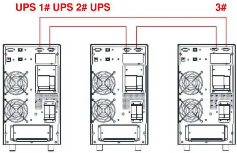
Fig 2-4: 3 UPS Paralleled System
NOTICE: must set the UPS is parallel system as "parallel work mode" via software according to "Annex A" before start parallel system
3 Controls and Indicators
![graph TD A["Monitor"] --> B["TEST/MUTE"] A --> C["OFF/ON"] B --> D["Arrow Left"] C --> E["Arrow Right"]](/content/2026/05/981208/images/bcfab1529ae5e845c3e0f68f085f5395145af272c932599f47fe1c784925d8b5.jpg)
Fig 3- 1: Display Panel
Description of Panel
| Controls Description | |
| 1. Press “ ↩” to power on the UPS from battery without utility power.NOTENot available when UPS is set in automatically start mode2. Press “ ≠ ”to start inverter when rectifier is OK3. Press “ ≠ ”to start the ups from battery without utility4. Press “ ↩” to confirm setting when in setting mode5. Press and hold“ ↩” to enter or exit the setting mode6. Press and hold “ ≠ ” to enter the self- test mode when ups is normal, otherwise to mute off the alarm, press and hold again to mute on. | |
| 1. Press “ ” to page up the LCD menu2. Press and hold “ ” to enter or exit the history inquiry interface3. Press “+” to shutdown inverter and transfer to bypass4. Press “+” to shutdown UPS completely when UPS is in battery mode | |
| ▶ | 1. Press“”to page down the LCD menu2. Press and hold“”to fault clear |
| Indicators Description | |
| 1. INV | Inverter indicator: green--inverter is normal, green flicker—rectifier or inverter is starting or tracking with bypass(ECO), dark—rectifier and inverter is not working |
| 2. BAT | Battery indicator: yellow—battery discharged, yellow flicker—No battery or battery alarm, dark—battery is connected |
| 3. BYP | Bypass indicator: yellow—bypass is normal, yellow flicker—bypass is abnormal and alarm ,dark—UPS is in normal mode and bypass is normal |
| 4. FAULT | FAULT indicator: red—UPS is abnormal, red flicker—UPS alarm ,dark—UPS is normal |

Fig 3- 2: LCD Menu
LCD display is divided into three areas: Icons display area, value display and settings area, and operation mode area.
◆ Icons display area :
◆ There are following contents in the area of display page
➢ Load and battery icons indicate load and battery capacity, and each square represents 25% of capacity. Load icon will flash when UPS is overloaded; battery icon will flash when battery capacity is too low or the battery is not connected.
➢ Fan icon indicates the working status of fans. Normally, the fan shows rotation status. The icon will flash if fans are disconnected or faulty;
➢ Buzzer icon indicates if the buzzer is mute. Normally, this icon doesn't display. Press and hold the “ ≠ ➤ ” buttons in battery or fault mode or set monitoring software to set MUTE ON in any mode, the UPS will get into mute status and the buzzer icon will be illuminated.
- Fault icon is illuminated in fault mode, it doesn't display in other cases.
◆ Value display and settings area:
◆ The area of menu setting page showing the settable menu options
◆ The area of event log query page showing page number of history records
In non- setting interface, it indicates the relevant information of UPS. Press the “◀” or “” button to display input voltage and frequency, output voltage and frequency, battery voltage and capacity, pieces of battery, load, temperature, software version, etc.
The fault code will be displayed in fault mode.
In menu setting interface, include rate voltage value (OPU), physical address(Id), parallel Enable (PAL), Expert mode (EP), Battery numbers(PCS), Emergency power off (EPO), etc.
◆ Operation mode area:
➢ After starting up in 5 seconds, this display area mainly indicates the UPS power rating. This function is settable.
This display area mainly indicates the UPS operation mode in 20 seconds after starting up, such as stdby (Standby mode), bypass (Bypass mode), online (Utility mode), bat (Battery mode), batt (Battery self test mode), fault (Fault mode), cucf (Frequency conversion mode), ECO (economy mode).
Description of LCD Menu:
| Page Description | |
 | Page 1 (output interface): Display UPS output information |
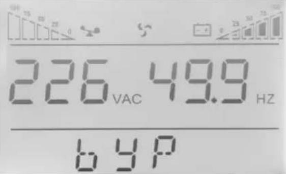 | Page 2 (bypass interface): Display UPS output information |
 | Page 3: Display UPS load information |
 | Page 4: Display UPS software version and temperature information |
 | Page 5: Display UPS input information |
 | Page 6: Display UPS battery voltage, battery capacity percentage |
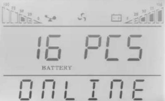 | Page 7: Display UPS battery numbers. |
 | Warning code Page: Display UPS warning code (ALA means alarm) All warning code information refer to “troubleshooting”. |
 | H - history, H01 - first history event. 044 - history event code.StS0-event appears. 1 - event disappearsHistory event query is for qualified personnel use only. |
✨ History event query
Press and hold the “◀” button to enter Event log query interface; Press inquiry button “◀” or “▶” to look over event logs with page turning. There are maximum 20 pages (600 piecesmonitoring software) event logs records. Press and hold the “◀” button again to return to the home screen.
Parameters setting
If want to set rated parameters, Press and hold "in setting mode, the
settable menu will flick.
| Charger current setting | Charger current could be set as follow, Press" "or " ► "to select, press" "to confirm selectionStandard model:1ALong backup model :1,2,3,4,5AOptional charger 12A for 6-10kVA:1-12AOptional charger 10A for 15-20kVA: 1-10A | 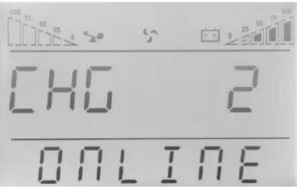 |
| Parallel ID setting | 1- parallel Id1In parallel mode, the parallel ID could be set as 1 to 19press " "or " ► to select, press" "to confirm selection |  |
| Parallel mode setting | Could selectON: parallel modeOFF: single modepress " "or " ► " to select, press" "to confirm selection | 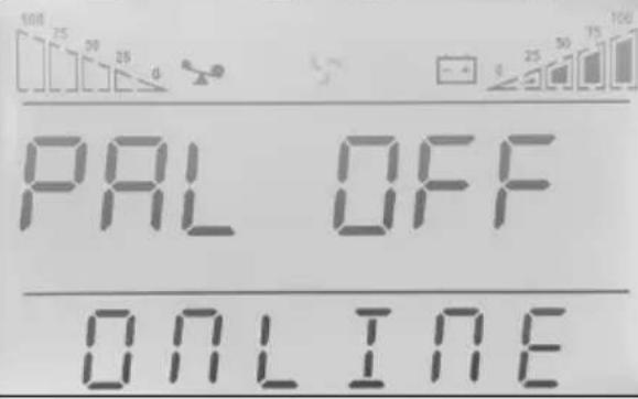 |
| EP mode setting | Could selectON: enable, you can selectEPO, ECO, Rated frequency,Battery number, Charger current settingOFF: disable (default doesn't work)Press" "or " ►" to select, press" ↩" to confirm selection |  |
| Rated voltage setting | Could select rated voltage as 208Vac/ 220Vac/ 230Vac/ 240Vac, press " "or " ►" to select, press" ↩" to confirm selection. The setting will be activated after restart UPS. |  |
| ECO mode setting | Could selectON: enableOFF: disablepress " "or " ►" to select, press" ↩" to confirm selection | 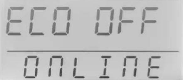 |
| EPO setting | Could selectON: enableOFF: disable (default doesn't work)Press" "or " ►" to select, press" ↩" to confirm selection |  |
| Battery number setting | Could select battery number as 16 blocks (192Vdc)18 blocks (216Vdc)20 blocks (240Vdc)press “” to select, press“”to confirm selection.The setting will be activated after restart UPS. |  |
| Rated frequency setting | Could select rated frequency as 50Hz/60Hz, press “” to select, press“”to confirm selection. The setting will be activated after restart UPS. |
NOTICE: when rated voltage is 200/208Vac, the output PF is 0.9. If other parameters are needed to change, please set it via monitoring software.
4 Operation
4.1 Operation Mode
4.1.1 Turn on the UPS in Normal Mode
(1) After you make sure that the power supply connection is correct, and then close the battery breaker (this step only for long backup time model), after that close the main input and bypass input breaker. At this time the fans rotate and the UPS operates in Bypass mode.
(2) After inverter LED start to flick, the BYPASS starts and bypass LED is yellow, now the output load is feed by bypass.
NOTE: In some application, UPS is set to start manually, you should press "→ + " to start inverter.
(3) The inverter LED is green, the UPS turn into normal working mode. If the utility power is abnormal, the UPS will operate in Battery mode without output interruption of the UPS.
4.1.2 Turn on the UPS from Battery without Utility Power
(1) After you make sure that the breaker of the battery pack is in the "ON" position (this step only for long backup time model).
(2) Press "button once to power on the UPS. Press" + "for 2s once buzzer is on."
(3) About 1 minute later, the UPS turns into Battery mode. If utility power recovers, UPS will transfer to normal mode.
4.1.3 Turn off the UPS in Normal Mode
(1) Shutdown the connected load and open external output breaker
(2)Press“ + button in condition of normal mode to transfer to bypass.
(3) For long backup model, open the mains input breaker and bypass input breaker, then open the battery breaker to turn off UPS completely.
(4) For standard model, open mains input and bypass input breaker, the UPS will shutdown completely after a few seconds.
4.1.4 Turn off the UPS in Battery Mode
(1) To power off the UPS by pressingthe“ + ▶ button for more than 1 second.
(2) When being powered off, the UPS will turn into No Output mode. Finally not any display is shown on the display panel and no voltage is available from the UPS output.
NOTICE: Please turn off the connected loads before turning on the UPS and turn on the loads one by one after the UPS is working in INV mode. Turn off all of the connected loads before turning off the UPS.

WARNING: Internal DC bus still has hazardous high votlage in several minutes, please wait minutes to open UPS. And check the DC bus votlage before maintenance.
4.2 Parallel Operation
4.2.1 Turn on the UPS of Parallel System
Make sure the power cables and communication cables are correctly. Shown as Fig 2-2, Fig 2-3, Fig 2-4:
(1) Close external output CB1 and CB2.
(2) Close mains input breakers and bypass input breakers of UPS1 and UPS2, after about 2 minutes, UPS work in parallel mode.
(3) Close external battery breakers.
(4) Turn on load. The load is now powered by parallel system.
4.2.2 Turn off Parallel System
(1) Turn off the connected load. Press the " + ▶ "button to transfer to bypass. Open output breakers. Open mains input and bypass input breakers of all UPS.
(2) If is long backup model, open external battery breakers. After a few seconds, the UPS will shut down completely.
4.2.3 How to install a new parallel UPS system
(1) Before installing a new parallel UPS system, user need to prepare the input and output wires, the output breaker, and the parallelcables.
(2) Open the input and output breakers of each UPS. Connect the inputwires, output wires and battery wires.
(3) Connect each UPS one by one with the parallel cables.
(4) Close the battery breakers and the input breakers of all of the UPS in the parallel system in turn.
(5) Turn on each UPS in turn and observe their display. Make sure that each UPSdisplays normal and all the UPS transfer to the INV mode normally.
4.2.4 How to remove a single UPS from the parallel system
(1) If you need to remove one UPS of the UPS parallel system which is in normal mode, press the “+” button of the UPS that is confirmed to be removed and the UPS will cut off its output immediately.
(2)Turnoff mains input breaker, bypass input breaker, the external mains input breaker, the output breaker and the battery breaker.
(3) Press the others UPS's" + button. A ll of them transfer to the Bypass mode.
(4) Remove the parallel cables of the UPS that need to be removed.
(5)Press“ + ”button of remained UPS to make the UPS transfer to INV output.
4.3 Maintenance Bypass Operation Mode
Maintenance bypass works when the inner of ups is cut off electric, output supply continuous electric for customer's loads.

Fig 4-1: Maintenance bypass
Maintenance bypass works under such procedures:
- UPS works normally, no need to maintenance
The input, bypass and output breakers are closed, but the maintenance bypass breaker is opened.
- Maintenance bypass mode
(1) Take off the panel used to cover the maintenance bypass breaker, the ups turns into bypass mode and alarms.
(2) Close the maintenance bypass breaker. turn off the output breaker.
(3) Turn off the output breaker, then the input and bypass breaker
(4) Turn off the battery switch (the long backup UPS needs to turn off switch for external battery, standard ups needs to take off battery from positive and negative ports)
- Maintenance is ok
(1) Connect the battery lines from positive to negative ports for standard UPS. Turn on the external battery switch for long backup mode.
(2) Close the input, bypass and output breaker.
(3) While the ups is in bypass mode, Turn off the maintenance bypass breaker. Then recover the panel for the breaker.
(4) Turn on the UPS.
5 Communication
UPS includes several communication ports: RS232, EPO, SNMP card, USB, dry contact, RS485.
NOTICE: Only one of SNMP card, dry contact and RS485 can be at the same time. Only one of RS232 and USB is available at the same time.
Connect the UPS and monitoring equipment (computer) by standard RS232 port (standard configuration) and standard USB port (optional configuration) to make single unit communication.
- Connect RS232 (or USB) cable to the serial port of the computer (or USB port)
- Connect RS232 (or USB) cable to the serial port of the UPS (or USB port)
5.1 RS232 and USBPort
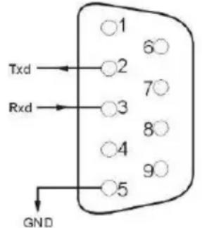
USB port (optional)

| Pins | 1 | 2 | 3 | 4 | 5 | |
| Definition | Empty | Transmit | Receive | Empty GND | ||
| Pins | 6 | 7 | 8 | 9 | ||
| Definition | Empty | Empty | Empty | Empty | ||
| Pins 1 2 | 3 4 | |||
| Definition | Power source + 5 V | Data+ | Data - | GND |
5.2 EPO Port
The Emergency Power Off (EPO) is a feature that will immediately disconnect all connected equipment from mains power. The remoted EPO is located on the rear panel of UPS with green terminals shown as Fig 1-2. It's normal opened, if it's closed, it will activate EPO function, the UPS will be shutdown.
NOTE: The system default EPO doesn't work, if you want to use this feature, need to set the monitoring software function.

In normal condition, pins ① and pins ② are opened; when perform Emergency Power Off, connect pins ① and pins ②.
5.3 Intelligent Cards (Optional)
The UPS has one intelligent slot for SNMP card, dry contacts card and RS485 card. Intelligent cards are installed in the intelligent slots on the UPS rear panel, and there is no need to stop the UPS during installation. The installation procedure is as follows:
- Remove the cover plate of the intelligent slots
- Insert the required intelligent card into the slot
● Tighten the screws
✨ SNMP card (optional)
SNMP card is used to monitor the UPS via TCP/IP, user can check the UPS status, voltage and current on the internet. Please refer to the user manual of SNMP card to get more detailed information.
✿ Dry contacts card (optional)
Insert dry contacts card into the intelligent slot to monitor and manage the UPS.
![graph LR A["UPS FAIL"] --> B["SUMMARY ALARM"] B --> C["GND"] C --> D["REMOTE SHUTDOWN"] D --> E["COMMON"] F["1"] --> G["6"] H["2"] --> I["7"] J["3"] --> K["8"] L["4"] --> M["9"] N["5"] --> O["LINE LOSS"] P["BYPASS"] --> Q["Output"] R["BATTERY LOW"] --> S["Output"] T["UPS ON"] --> U["Output"]](/content/2026/05/981208/images/44b852553a518f98a26bd640b8ddc4bb1805d8b94f4f90187c9d6e247af9b079.jpg)
| Pins Definition | |
| PIN1 Close: UPS fault | |
| PIN2 Close: Alarm sounds (system fault) | |
| PIN3 Grounding | |
| PIN4 | Remote shutdown |
| PIN5 Common | |
| PIN6 Close: bypass working | |
| PIN7 | Close : low battery |
| PIN8 | Close : UPS workingOpen : bypass working |
| PIN9 | Close : Malns power Off |
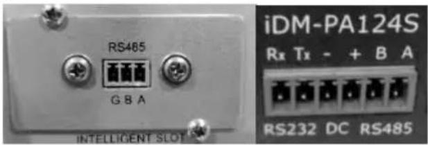
RS485 card (optional)
RS485 is optional function for user to integrated monitoring and communication. RS485, SNMP and dry contact are installed in one intelligent slot A and B on the right side of ports are RS485 output, A is “+”, B is “-”
6 Maintenance
This chapter includes battery maintenance, battery disposal and replacement, check UPS status and function.
6.1 Battery Maintenance
The UPS only requires minimal maintenance. The batteries used for standard models are value regulated, sealed lead-acid, maintenance free battery. When being connected to the utility power, whether the UPS is turned on or not, the UPS keeps charging the batteries and also offers the protective function of overcharging and over-discharging.
(1)The UPS should be charged once every 4 to 6 months if it has not been used for a long time.
(2) In the regions of hot climates, the battery should be charged and discharged every 2 months. The standard charging time should be at least 12 hours.
(3) Under normal conditions, the battery life lasts 3 to 5 years. In case if the battery is found in bad condition, earlier replacement should be made.
(4) Battery replacement should be performed by qualified personnel.
(5) Replace batteries with the same number and same type of batteries.
(6) Do not replace the battery individually. All the batteries should be replaced at the same time following the instructions of the battery supplier.
6.2 Battery Disposal
(1) Before disposing of batteries, remove jewelry, watches and other metal objects.
(2) Use rubber gloves and boots, use tools with insulated handles.
(3) If it is necessary to replace any connection cables, please purchase the original materials from the authorized distributors or service centers, so as to avoid overheat or spark resulting in fire due to insufficient capacity.
(4) Do not dispose of batteries or battery packs in a fire. The batteries may explode.
(5) Do not open or mutilate batteries, released electrolyte is highly poisonous and harmful to the skin and eyes.
(6) Do not short the positive and negative of the battery electrode, otherwise, it may result in electric shock or fire.
(7) Make sure that there is no voltage before touching the batteries. The battery circuit is not isolated from the input potential circuit. There may be hazardous voltage between the battery terminals and the ground.
(8) Even though the input breaker is disconnected, the components inside the UPS are still connected with the batteries, and there are potential hazardous voltages. Therefore, before any maintenance and repairs work is carried out, switch off the breaker of the battery pack or disconnect the jumper wire of connecting between the batteries.
(9) Batteries contain hazardous voltage and current. Battery maintenance such as the battery replacement must be carried out by qualified personnel who are knowledgeable about batteries. No other persons should handle the batteries.
6.3 Battery Replacement Procedures
(1) Press“ + button to transfer to bypass mode
(2) Close the manual bypass breaker
(3) Remove both side covers from the UPS.
(4) Disconnect the battery wires one by one.
(5) Remove metal bars which are used to fasten batteries.
(6) Replace batteries one by one.
(7) Screw metal bars back to UPS.
(8) Connect the battery wires one by one. Take care of electrical shock while connecting the last wire.
6.4 Precaution
Although the UPS has been designed and manufactured to ensure personal safety, improper use can result in electrical shock or fire. To ensure safety, observe the following precautions:
(1) Turn off the UPS before cleaning it;
(2) Clean the UPS with a dry cloth. Do not use liquid or aerosol cleaners;
(3) Never block or insert any objects into the ventilation holes or other openings of the UPS;
6.5 Checking UPS Status
It is recommended to check the UPS once every half year.
(1) Check if the UPS is faulty: Are the LED indicators abnormal? Is there any alarm?
(2) Check if the UPS is working in bypass mode: Normally, the UPS works in normal mode, if it's working in bypass mode, please check: overload, internal fault and so on.
(3) Check if the battery is discharging: When the mains input is normal, the battery should not discharge, if the UPS is working in battery mode, please check: if mains input is failure, battery test, operator intervention and so on.
7 Troubleshooting
This chapter describes checking the UPS's status. This section also indicates various UPS symptoms a user may encounter and provides a troubleshooting guide in the event the UPS develops a problem. Use the following information to determine whether external factors caused the problem and how to remedy the situation.
If UPS alarms and buzzer sound, please press “ ” to get alarm code on t he menu of alarm code on LCD. And press and hold” ” to manually fault clear. If alarms is still existent, please check the problem follow the Table 7-1:
LCD display in fault mode is shown as below:

Fig 7- 1: Fault code
Fault code informing:
| Fault Code | Cause | Solution |
| 35 - 39 Inverter forbidden / | ||
| 40 - 44 over temperature | Rectifier heat sink is over temperature or the temp sensor is not connected correctly. Check if fans are working normally Check if anything block ventilation Check if the sensor is connected correctly Check if the environmental temp is over the range of UPS | |
| 45 - 49 Output shorted | Load is abnormal or output breaker is shorted. Check if load is abnormal and the faulty load is shutdown Check if output breaker is faulty If the faulty load is removed, please manually fault clear to restart UPS. | |
| 50 - 54 | Overload | Inverter is overload, please remove numbers of non-critical loads, or else UPS could transfer to bypass If bypass overload, Check the load and remove some non-critical load until the load is below 95% |
| 55 - 59 Negative power fault | Please contact your supplier. | |
| 85 - 89 Bus short | Please contact your supplier. | |
| 120 - 124 | Inverter fault | Inverter voltage is abnormal, or inverter IGBT opened. Please manually clear the fault and if the fault is still on, please contact with local dealer |
| 130 - 134 Inverter relay opened | Inverter relay is opened. Please contact with local dealer | |
| 135 - 139 Rectifier fault | DC bus over voltage, low voltage, shorted or IGBT opened. Please manually clear the fault and if the fault is still on, please contact with local dealer | |
| 145 - 149 | Fan fault | One or more fans are faulty or blocked Check if all fans working normally Check if something blocks fan |
| 150 - 154 EPO | Check if EPO is closed correctly Check if EPO is activated manually | |
| 155 - 159 SPS abnormal | Please contact your supplier. | |
Note:
Contact the supplier if display screen shows other fault information. After troubleshooting, please manually fault clear to restart UPS.
LCD display warning code is as shown below (ALA means alarm):

Fig 7-2: Warning code
Warning code informing:
| Warning code | Warning name | Solutions |
| 200 | Parallel cables error | Check if all parallel communication cables are connected correctly |
| 202 | Battery reversed | Check if battery cables are connected correctlyCheck if inverter cables of battery packs are connected correctly |
| 203 Overload | Remove non-critical devices to reduce the loads connected to UPS. | |
| 204 | No battery | Check if the battery cables are connected correctlyCheck battery breaker or fuses are openedCheck if batteries are damaged |
| 205 Input over current | Check if rectifier IGBT is broken, DC bus is shorted, or IGBT drivers are lost, input voltage display is wrong. | |
| 206 | Battery overcharged | Switch off battery breaker, remove devices connected to UPS, shutdown UPS, and replace new charger. |
| 208 | Charger fail | Charger is faulty or is not disconnected. Please contact with local dealer |
| 209 | EEPROM fault | Clean the warning by LCD panel or using debug software. Or shutdown UPS and startup again. |
| 210 | Input over current time out | Check the input voltage is abnormal |
| 211 | Battery voltage low | Remove non-critical devices and charge the battery as soon as possible. |
| 214 | Synchronize signal loss | Check whether the parallel wire connecting and parallel boards are abnormal or not. |
| 215 | CAN communication fail | Check whether the parallel wire connecting and parallel boards are abnormal cr not. |
| 217 | Bypass fault | Check whether bypass voltage is normal or not. |
| 220 | Over synchronization | Bypass voltage or frequency is over tracking range. There could be interruption if manually transfer to bypass or inverter is faulty |
| 221 | Over transfer times | Mains and battery or inverter and bypass transfer for 5 times in 1hour |
| 222 | End of discharge Char | ge the battery as soon as possible. |
| 223 | Battery test ok | |
| 224 | Forbidden startup UPS | Check whether mains voltage and frequency is normal or not. |
| 225 Battery test is abnormal / | ||
| 226 Parallel current unbalance | Check whether the parallel wire connecting and parallel boards are abnormal or not. | |
| 228 Battery maintenance ok / | ||
| 229 | Battery maintenance is abnormal | / |
| 230 Input current unbalance / | ||
| 233 | Over transfer times | Mains and battery transfer for 5 times in 1hour,while Bus is low |
| 234 | Utility abnormal | UPS mains input is abnormal.Check if mains input is normalCheck if mains input voltage and frequency is over the working rangeCheck if mains input breaker or external input breaker is openedCheck if the input phase sequence against Please recover mains input power, otherwise output will be shutdown if battery is discharged to EOD |
| 235 | Bypass abnormal | Check if bypass input power is abnormalCheck if bypass input breaker is openedPlease recover bypass input power, otherwise there will be no backup circuit when UPS is faulty |
| 238 | Battery voltage is abnormal(reserved) | / |
| 241 | Manual bypass on | Manual bypass is closed, the UPS will transfer to bypass and forbidden to transfer back to inverter |
Annex A Parallel Setting
- Connect UPS1# with RS232 cable to PC. Connect UPS with monitoring software "i-ServerceTool". Select "EA900P6-20K G4".

- Enter in menu "Settings", set "device address" as "1" and "baud rate" as "9600", select the right serial port in menu "Communication Setting". Click "OK" to connect UPS
- Enter in menu "Scene", set "System Work Mode" as "Parallel Operation", "Parallel device number" as "2", "Parallel device address" as "1" in the menu "Parameter Setting". Click "ok" to confirm setting. If there are 3 UPS are paralleled, Set "Parallel device number" as "3".

- Connect UPS2# and set "System Work Mode" as "Parallel Operation", "Parallel device number" as "2", "Parallel device address" as "2" in the menu "Parameter Setting". Click "ok" to confirm setting. If there are 3 UPS are paralleled, Set "Parallel device number" as "3".
Notice: Setting the "Parallel device address" as "2" will cause communication fail, please reset "device address" as "2" in menu "Communication Setting" to reconnect UPS.
- Connect UPS3# and set "System Work Mode" as "Parallel Operation", "Parallel device number" as "3", "Parallel device address" as "3" in the menu "Parameter Setting".
You also can set the "Parallel mode" and "Parallel ID" by the LCD.
-
Power on the UPS1#, Press and hold "to enter the setting mode, "Id", Set "Parallel mode" as "ON" and "Parallel ID" as "1".Press "of confirm selection
-
Power on the UPS2#, Press and hold "to enter the setting mode, "Id", Set "Parallel mode" as "ON" and "Parallel ID" as "2".Press "or confirm selection
Press"◀"or" "to"PAR" and "▶" to select, press"◀"to
Press"◀"or" "to"PAR" and "▶" to select, press"◀"to

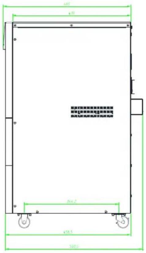
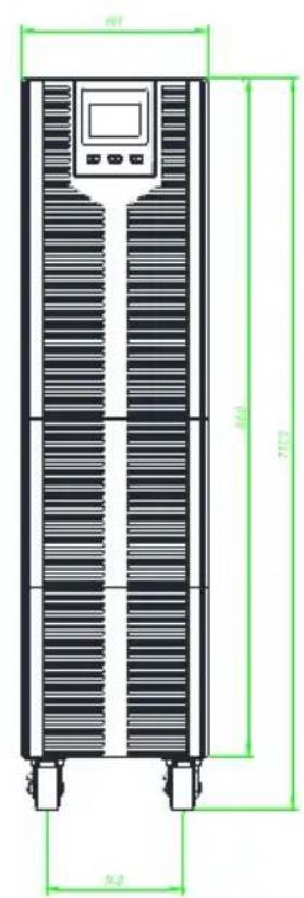
Annex B Mechanical Size
6kVA / 10kVA model
Annex C Battery Run Time
Standard battery pack includes 16 blocks 9Ah batteries. Please refer to the table below for the battery runtime to configure battery packs.
| Pack's number | UPS | Backup Time (mins) | ||||||||||
| 1KW | 2KW | 3KW | 4KW | 5KW | 6KW | 7KW | 8KW | 9KW | 10KW | |||
| 1 6k 60 | 25 16 | 10 6 / | / / | / / | ||||||||
| 10k 60 | 25 16 | 10 6 | / / / | / / | ||||||||
| 2 6k 180 | 60 30 | 24 20 | 16 / / | / / | ||||||||
| 10k 180 | 60 30 | 24 20 | 16 13 | 10 | 8 7 | |||||||
| 3 6k 240 | 120 60 | 40 28 | 23 / | / / | ||||||||
| 10k 240 | 120 60 | 40 28 | 23 20 | 18 | 16 15 | |||||||
| 4 6k 360 | 180 110 | 60 42 | 30 / | / / | ||||||||
| 10k 360 | 180 110 | 60 42 | 30 26 | 23 | 21 20 | |||||||
| 5 6k 480 | 210 150 | 90 60 | 46 / | / / | ||||||||
| 10k 480 | 210 150 | 90 60 | 46 37 | 28 | 25 22 | |||||||
NOTICE: Backup time of batteries is depending on other facts such as battery brand, working temperature, working time and so on, the table is calculated according to ideal situation.
NOTICE: Set charger current according to battery capacity, the charger current should not be larger than 0.2C, normally the charger current is set as 0.1C. Too large charger current could damage the batteries.
Software Download & Installation
(Only for the model with communication port)
Please follow steps below to download and install monitoring software:
- Go to the website https://www.energenie.com/products.aspx?sg=88, select you product model
- Find and click software icon to download the software
- Run it and follow the on-screen instructions to install the software
GENERAL INFORMATION
This product has been manufactured by or on behalf of Gembird Europe B.V.. Inquiries to the EU Importer or related to product compliance in Europe should be sent to: Gembird Europe B.V., Wittevrouwen 56, 1358 CD, Almere, The Netherlands. www.gmb.nl
Warranty conditions: www.gmb.nl/warranty
Product support: www.gmb.nl/service and/or helpdesk@gembird.nl
SAFETY
(ENG) To ensure safe handling of the product, follow the safety advice on: (DE/AT) HinweisezumsicherenGebrauch der Produktefinden Sie auf: (NL/BE) Vooreenveiliggebruik van het product volgt u dezealgemeneveiligheidsaanwijzingen op: (ES) Para garantizarunamanipulaciónsegura de losdispositivos , siça las advertencias de seguridaddisponiblesen: (CZ) Abystezajistilibezpečnoumanipulaci s výrobkem, dodržujtebezpečnostní pokynyna: (FR/BE) Pour garantirune manipulation sûre des appareils, suivez les consignes de sécurité sur: (IT) Per garantireunamanipolazionesicura del prodotto, seguireiconsigli di sicurezzasu: (PT)Para garantir o manuseioseguro do produto, siga as recomendações de segurançaem: (PL) Aby obchodzić się bezpiecznie z produktami, należyprzestrzegać wskazówekdotyczącychbezpieczeństwa: (RO) Pentruasigurareauneimanipulăriîncondiții de siguranță a produsului , urmațirecomandările de securitate de pe: (SK) Na zai steniebezpečnejmanipulácie so zariadeniamisariadtebezpečnostnýmipokynmina: (SL) Za zagotavljanjevarnegaravnanja z napravami, upoštevajtevarnostnanavodila , ki jihnajdetena: (HR) Da bisteosiguralisigurnorukovanjeuredajima, pratitesigurnosnesavjetena web-mjestu: (HU) A készülékekbiztonságoskezelésénekérdekébenkövesse a biztonságitanácsokat(BG) Задаосигуритебезопаснаработанаустройствата, следвайтесьветитезабезопасностпо-долу: www.gmb.nl/safety
DECLARATION OF CONFORMITY
(ENG) Hereby, Gembird Europe B.V., declares that this equipment is in compliance with Directive LVD (2014/35/EU), EMC (2014/30/EU), RoHS (2011/65/EU). The full text of the EU declaration of conformity is available at the following internet address: www.gmb.nl/certificates (DE/AT) Hiermiterklärt Gembird Europe B.V., dassdieseFunkanlage der Richtlinie LVD (2014/35/EU), EMC (2014/30/EU), RoHS (2011/65/EU)entspricht. Der vollständige Text der EU Konformitätserklärung ist unter der folgenden Internetadresse verfügbar: www.gmb.nl/certificates (NL/BE) Hierbij verklaart Gembird Europe B.V. dat deze radioapparatuur conform is met Richtlijn LVD (2014/35/EU), EMC (2014/30/EU), RoHS (2011/65/EU). De volledige tekst van de EU-conformiteitsverklaring kan worden geraadpleegd op het volgende internetadres: www.gmb.nl/certificates (ES) Por la presente, Gembird Europe B.V. declara que este equipo es conforme con la L'VD (2014/35/EU), EMC (2014/30/EU), RoHS (2011/65/EU). El texto completo de la declaración UE de conformidad está disponible en la dirección de Internet siguiente: www.gmb.nl/certificates (CZ) Gembird Europe B.V. potvrzuje, że toto rádiové zařízení je v souladu se směrnicí LVD (2014/35/EU), EMC (2014/30/EU), RoHS (2011/65/EU). Úplné znění EU prohlášení o shodě je k dispozici na následující internetové adrese: www.gmb.nl/certificates (FR/BE) Le soussigné, Gembird Europe B.V., déclare que cet équipement est conforme à la Directive LVD (2014/35/EU), EMC (2014/30/EU), RoHS (2011/65/EU). Le textecomplet de la déclaration UE de conformité est disponible à l'adresse internet suivante: www.gmb.nl/certificates (IT) Con la presente, Gembird Europe B.V.
dichiarachequestoapparecchioè conformeallaDirettiva LVD (2014/35/EU), EMC (2014/30/EU), RoHS (2011/65/EU). Il testo completodelladichiarazione di conformità UE è disponibile al seguenteindirizzo Internet: www.gmb.nl/certificates (PT) A Gembird Europe B.V. certifica que esteequipamento de rádioestá emconformidade com a Diretiva LVD (2014/35/EU), EMC (2014/30/EU), RoHS (2011/65/EU). O textocompleto da Declaração de Conformidade da UE está disponível no seguinteendereço da Internet: www.gmb.nl/certificates (PL) Gembird Europe B.V. zaświadcza, że to urządzenieradiowe jest zgodne z Dyrektywą LVD (2014/35/EU), EMC (2014/30/EU), RoHS (2011/65/EU). PełnytekstDeklaracjiZgodności UE jest dostępny pod następującymadreseminternetowym: www.gmb.nl/certificates (RO) Gembird Europe B.V. certifică că acestechipament radio respectă Directiva LVD (2014/35/EU), EMC (2014/30/EU), RoHS (2011/65/EU). Textul integral al Declaratiei de conformitate UE estedisponibil la următoareaadresă de internet: www.gmb.nl/certificates (SK) Gembird Europe B.V. potvrdzuje, že toto rádiové zariadenie je v súlade so smernicou LVD (2014/35/EU), EMC (2014/30/EU), RoHS (2011/65/EU). Úplné znenievyhlásenia o zhode EÚ je k dispozíciinatejtointernetovejadrese: www.gmb.nl/certificates (SL) Gembird Europe B.V. potrjuč, da je ta radijskaoprema v skladu z DirektivoLVD (2014/35/EU), EMC (2014/30/EU), RoHS (2011/65/EU). Celotnobesediloizjave EU o skladnosti je navoljonanaslednjemspletnemnaslovu: www.gmb.nl/certificates (HR) Gembird Europe B.V. potvrđuje da je ova radijskaoprema u skladu s Direktivom LVD (2014/35/EU), EMC (2014/30/EU), RoHS (2011/65/EU). Potpunitekst EU Izjave o sukladnostidostupan je nasljedećoj internet adresi: www.gmb.nl/certificates (HU) A Gembird europe B.V. tanúsítja, hogyez a rádióberendezésmegfelel a LVD (2014/35/EU), EMC (2014/30/EU), RoHS (2011/65/EU) irányelvnek. Az EU megfelelőséginyilatkozatteljesszövege a következő internetescímenérhető el: www.gmb.nl/certificates (GR) Δια του παρόντος, η Gembird Europe B.V., δηλώνειότι αυτός ο εξοπλισμός συμμορφώνεται μετηνΟδηγία LVD (2014/35/EU), EMC (2014/30/EU), RoHS (2011/65/EU). Το πλήρεκείμενοτηςδήλωσηςσυμμόρφωσης ΕΕ διατίθεται στην ακόλουθηδιεύθυνσηΔιαδικτύου: www.gmb.nl/certificates (BG) Gembird Europe B.V. удостоверява, четоварадиооборудванеотговаряна ДирективаLVD (2014/35/EU), EMC (2014/30/EU), RoHS (2011/65/EU). Пълният текст на ЕС декларацията за съответствие е достъпен на следния интернет адрес: www.gmb.nl/certificates

(ENG) Waste disposal:
The symbol of the crossed-out wheeled bin means that this appliance must not be disposed of with household waste at the end of its useful life. The appliance must be disposed of in specially set-collection points, recycling yards or disposal companies. Retailers of electrical appliances with a sales area of at least 400 m 2 for electrical appliances and grocers with an area of 800 m 2 , which offer electrical equipment several times a year, are obliged to take back electrical equipment. Return and disposal are free of charge for you. When you purchase a new device, you have the right to return a corresponding old device free of charge. Please delete all personal data before returning the appliance. Before returning, please remove the batteries or re-chargeable batteries that are not enclosed by the old device, as well as lamps that can be removed without destruction, and dispose them to a separate collection. (DE/AT) Entsorgungshinweise: Das Symbol der durchgestrichenen Mülltonne bedeutet, dass dieses Gerät am End eder Nutzungszeit nicht über den Haushaltsmüll entsorgt werden darf. Das Gerät ist bei eingerichteten Sammelstellen, Wertstoffhöfen oder Entsorgungsbetrieben abzugeben. Händler von Elektrogeräten mit einer Verkaufsfläche von mind. 400 m² für Elektrogeräte und ebensmittelhändler mit einer Fläche von 800 m², die mehrfach im Jahr Elektrogeräte anbieten sind verpflichtet Elektrogeräte zurückzunehmen. Rückgabe und Entsorgung sind für Sie kostenfrei. Beim Kauf eines Neugerätes haben Sie das Recht, ein entsprechendes Altgerät unentgeltlich zurückzugeben. Bitte löschen Sie vor der Rückgabe alle personenbezogenen Daten. Bitte entnehmen Sie vor der Rückgabe Batterien oder Akkumulatoren, die nicht vom Altgerät umschlossen sind, sowie Lampen, die zerstörungsfrei entnommen werden können und führen diese einer separaten Sammlung zu. (NL) Afvalverwijdering: Het symbool van de doorgekruiste afvalbak betekent dat dit apparaat aan het einde van zijn levensduur niet bij het huisvuil mag worden gegooid. Het apparaat moet worden afgevoerd naar speciaal daarvoor ingerichte inzamelpunten, recyclingbedrijven of afvalverwerkingsbedrijven. Detailhandelaren in elektrische apparaten met een verkoopoppervlakte van ten minste 400 m² voor elektrische apparaten en kruideniers met een oppervlakte van 800 m² die meerdere keren per jaar elektrische apparaten aanbieden, zijn verplicht elektrische apparaten terug te nemen. Retourneren en afvoeren is voor u gratis. Bij aanschaf van een nieuw apparaat heeft u het recht om een bijbehorend oud apparaat kosteloos te retourneren. Wis alle persoonlijke gegevens voordat u het apparaat retourneert. Verwijder voor het retourneren batterijen of oplaadbare batterijen die niet bij het oude apparaat zijn ingesloten, evenals lampen die zonder vernietiging kunnen worden verwijderd, en lever deze in bij een gescheiden
inzamelpunt. (FR/BE) Traitement des déchets: Le symbole de la poubelle barrée d'une croix signifie que cet appareil ne doit pas être jeté avec les ordures ménagères en fin de vie. L'appareil doit être déposé dans des points de collecte spécialement aménagés, des parcs de recyclage ou des entreprises d'élimination. Revendeurs d'appareils électroménagers disposant d'une surface de vente d'au moins 400 m² pour appareils électroménagers et épiciers d'une superficie de 800 m², qui proposent du matériel électrique plusieurs fois par an, sont dans l'obligation de reprendre le matériel électriqueLe retour et l'élimination sont gratuits pour vous. Lorsque vous achetez un nouvel appareil, vous avez le droit de retourner gratuitement un ancien appareil correspondant. Veuillez supprimer toutes les données personnelles avant de retourner l'appareil. Avant de retourner, veuillez retirer I es piles ou les piles rechargeables qui ne sont pas enfermées dans l'ancien appareil, ainsi que les lampes qui peuvent être retirées sans destruction, et les jeter dans une collecte séparée.(PL) Utylizacja odpadów: Symbol przekreślonego kosza na smileci na kółkach oznacza, że tego urządzenia nie wolno wyrzucać wraz z odpadami domowymi po zakończeniu jego okresu użytkowania. Urządzenie należy zutylizować w specjalnie do tego wyznaczonych punktach zbiórki, punktach recyklingu lub firmach zajmujących się utylizacja odpadów. Sprzedawcy sprzetu elektrycznego o powierzchni sprzedaży co najmniej 400 m² sprzętu elektrycznego oraz sklepy spożywcze o powierzchni 800 m², które oferują sprzęt elektryczny kilka razy w roku, są zobowiązane do odbioru sprzętu elektrycznego. Zwrot i utylizacja są dla Państwa bezpłatne. Kupując nowe urządzenie, masz prawo do bezpłatnego zwrotu odpowiedniego starego urządzenia. Przed zwróceniem urządzenia należy usunąć wszystkie dane osobowe. Przed zwrotem należy wyjąć baterie lub akumulatorki, które nie są dołączone do starego urządzenia, a także lampki, które można wyjąć bez zniszczenia i przekazać je do osobnej zbiórki. (CZ) Likvidace odpadu: Symbol přeškrtnutého kontejneru na kolečkách znamená, że tento spotřebič nesmi být na konci své životnosti likvidován s domovním odpadem. Spotřebič musí být zlikvidován ve speciálně zřízených sběrných místech, recyklačních dvorech nebo společnostech pro likvidaci odpadu. Povinností zpětného odběru elektrozařízení jsou maloobchodnici s elektrospotřebiči s prodejní plochou minimálně 400 m² u elektrospotřebičů a potraviny s plochou 800 m², kte ří nabízejí elektrozařízení několikrát ročně. Vrácení a likvidace jsou pro vás zdarma. Pří nákupu nového zařízení máte právo zdarma vrátit odpovidající staré zařízení. P řed vrácerím spotřebiče vymažte všechna osobní data. Před vrácením vyjměte baterie nebo dobíjecí baterie, které nejsou přiloženy ke starému zařízení, stejně jako lampy, které lze vyjmout bez zničení, a odevzdejte je do odděleného sběru.(SK) Likvidácia odpadu: Symbol prečiarknutého odpadkového koša na kolieskach znamená, že tento spotřebič sa po skončení životnosti nesmie likvidovať s domovým odpadom. Spotřebič sa musí likvidovať na špeciálne zriadených zberných miestach, v recyklačných dvoroch alebo v spoločnostiach na likvidáciu odpadu. Maloobchod s elektrospotrebičmi s predajnou plochou najmenej 400 m² pre elektrospotrebiče a potraviny s plochou 800 m², ktorí ponúkajú elektrozariadenia niekolíkokrát do roka, sú povinní prevziat’ elektrozariadenia. Vrátenie a likvidácia sú pre vás bezplatné. Pri kúpe nového zariadenia máte právo bezplatne vrátiť zodpovedajúce staré zariadenie. Pred vrátením spotrebiča vymažte všetky osobné údaje. Pred vrátením vyberte batérie alebo nabíjateľné batérie, ktoré nie sú pribalené k starému zariadeniu, ako aj lampy, ktoré je možné vybrat’ bez zničenia, a odovzdajte ich na separovaný zber.(ES) Deposito de basura: El símbolo del contenedor con ruedas tachado significa que este aparato no debe desecharse con la basura doméstica al final de su vida útil. El aparato debe desecharse en puntos de recogida, vertederos de reciclaje o empresas de eliminación de residuos especialmente habilitados. Minoristas de electrodomésticos con una superficie de venta de al menos 400 m² de electrodomésticos y ultramarinos con una superficie de 800 m², que ofrecen equipos eléctricos varias veces al año, están obligados a retirar equipos eléctricos. La devolución y la eliminación son gratuitas para usted. Cuando compra un dispositivo nuevo, tiene derecho a devo Iver el dispositivo antiguo correspondiente de forma gratuita. Elimine todos los datos personales antes de devolver el aparato. Antes de devolverlo, retire las baterías o las baterías recargables que no estén incluidas en el dispositivo antiguo, así como I as lámparas que se puedan quitar sin destruirlas, y deséchelas en un lugar de recolección separado. (PT) Eliminação de residuos: O símbolo do caixote do lixo com uma cruz significa que este aparelho não deve ser eliminado juntamente com o lixo doméstico no final da sua vida útil. O aparelho deve ser descartado em pontos de coleta especialmente estabelecidos, pontos de reciclagem ou empresas de descarte. Os retalhistas de electrodomésticos com uma área de venda de pelo menos 400 m² para electrodomésticos e m ercearias com uma área de 800 m², que oferecem material eléctrico várias vezes por ano, são obrigados a aceitar a devolução do material eléctrico. A devolução e eliminação são gratuitas para si. Ao comprar um novo dispositivo, você tem o direito de devolver gratuitamente um dispositivo antiguo correspondente. Apache todos os dados pessoais antes de devolver o aparelho. Antes de devolver, remova as baterias ou baterias recarregáveis que não estão incluídas no dispositivo antiguo, bem como as lâmpadas que podenser removidas sem destruição e descarte-as em uma coleta seletiva. (IT) Smaltimento rifiuti: Il simbolo del bidone su ruote barrato significa che questo apparecchio non deve essere smaltito insieme ai rifiuti domestici al termine della sua vita utile. L'apparecchio deve essere smaltito in punti di raccolta appositamente predisposti, centri di riciclaggio o ditte di smaltimento. Rivenditori di eletrodomestici con una superficie di vendita di almeno 400 m² per eletrodomestici e alimentary con una superfici e di 800 m², che offrono apparecchiature elettriche più volte all'anno, sono obbligate a ritirare le apparecchiature elettriche. La restituzione e lo smaltimento sono gratuity per te. Quando acquisti un nuovo dispositivo, hai il diritto di restituire gratuitamente un vecchio dispositivo corrispondente. Si prega di cancellare tutti i dati personali prima di restituire l'apparecchio. Prima della restituzione, rimuovere le batterie o le batterie ricaricabili non incluse nel Vecchio dispositivo , nonché le lampade che possono essere rimosse senza distruzione, e smaltirle in una raccolta separata. (HR) Odlaganje smeća: Simbol prekrižene kante za smeće na kotačićima znači da se ovaj uređaj ne smije odlagati s kućnim otpadom na kraju njegovog životnog vijeka. Uređa j se mora odložiti na posebno postavljenim sabirnim mjestima, reciklažnim dvorištima ili trtkama za zbrinjavanje. Trgovci na malo električnim uređajima s prodajnom površinom od najmanje 400 m² za električne uređaje i trgovine mješovitom robom s površinom od 800 m², koji nude električnu opremu nekoliko puta godišnje, dužni su preuzeti električnu opremu. Povrat i zbrinjavanje su za vas besplatni. Kada kupite novi uređaj, imate pravo vratiti odgovarajući stari uređaj bez naknade. Prije vraćanja uređaja izbrišite sve osobne podatke. Prije povrata uklonite baterije ili punjive baterije koje nisu priložene starom uređaju, kao i svjetiljke koje se mogu izvaditi bez uništenja, te ih odložite u zasebno prikupljanje (SI) Odlaganje odpadkov: Simbol prečrtanega smetnjaka na kolesih pomeni, da tega aparata po koncu njegove življenjske dobe ne smete zavreči med gospodinjske odpadke. Napravo je treba oddati na posebej postavljenih zbirnih mestih, reciklažnih mestih ali v podjetijih za odstranjevanje odpadkov. Trgovci na drobno z električnim aparati s prodajno površino najmanj 400 m² za električne aparate in živilske trgovine s površino 800 m², ki ponujajo električno opremo večkrat letno, so dolžni prevzeti električno opremo. Vračilo in odlaganje sta za vas brezplačna. Ob nakupu nove naprave imate pravico do brezplačnega vračila pripadajoče stare naprave. Pred vračilom aparata izbrišite vse osebne podatke. Prosimo, da pred vračilom
odstranite baterije ali polnilne baterije, ki niso priložene stari napravi, ter svetilke, ki ji h je mogoče odstraniti brez uničenja, in jih odvrzite na ločeno zbirališče. (HU) Hulladékkezelés: Az áthúzott, kerekes szemeteskuka szimbóluma azt jelenti, hogy a készüléket hasznos élettartama végén nem szabad a háztartási hulladékkal együtt kidobni. A ké szüléket speciálisan kialakított gyűjtőhelyeken, újrahasznosító telepeken vagy ártalmatlanító cégekben kell leadni. Elektromos készülékek kiskereskedői legalább 400 m²-es elektromos készülékek és élelmiszerboltok értékesítési területével 800 m² alapterület ü, évente többször kínáló elektromos berendezéseket kötelesek visszavenni. A visszaküldés és a selejtezés ingyenes az On számára. Uj készülék vásárlásakor jogában áll a megfelelő régi készüléket ingyenesen visszaküldeni. Kérjük, a készülék visszaküldése el ött töröljön minden személyes adatot. Kérjük, hogy visszaküldés előtt távolítsa el az elemeket vagy újratölthető elemeket, amelyeket nem zárt be a régi készülék, valamint a roncsolás nélkül eltávolítható lámpákat, és helyezze el a szelektív gyűjtőbe. (RO) Eliminarea deșeurilor: Simbolul coşului de gunoi tăiat cu roți înseamnă că acest aparat nu trebuie aruncat împreună cu deșeurile menajere la sfârșitul duratei sale de viață. Aparatul trebuie aruncat în puncte de colectare special amenajate, curți de recicl are sau companii de eliminare. Comercianții cu amănuntul de aparate electrice cu o suprafață de vânzare de cel puțin 400 m² pentru electrocasnice și băcănii cu o suprafață de 800 m², ca re oferă echipamente electrice de mai multe ori pe an, sunt obligați să recupereze echipamentele electrice. Returnarea și eliminarea suni gratuite pentru dvs. Când achizi ționați un dispozitiv nou, aveți dreptul de a returna gratuit un dispozitiv vechi corespunzător. Vă rugăm să ștergeți toate datele personale înainte de a returna aparatul. Înainte de a returna, vă rugăm să scoateți bateriile sau bateriile reîncărcabile care nu sunt incluse în vechiul dispozitiv, precum și lămpile care pot fi îndepărtate făă distrugere și aruncați-le într-o colectare separată. (GR) Απόρριψη απορριμμάτων: Το σύμβολο του διαγραμμένου κάδου απορριμμάτων σημαίνει ότι αυτή η συσκευή δεν πρέπει να απορρίπτεται μαζί με τα οικιακά απορρίμματα στο τέλος της ωφέλιμης ζωής της. Η συσκευή πρέπει να απορρίπτεται σε ειδικά διαμορφωμένα σημεία συλλογής, ναυτηγεία ανακύκλωσης ή εταιρείες απόρριψης. Οι έμποροι ηλεκτρικών συσκευών με επιφάνεια πώλησης τουλάχιστον 400 m² για ηλεκτρικές συσκευές και τα παντοπωλεία επιφάνειας 800 m², που προσφέρουν ηλεκτρικό εξοπλισμό πολλές φορές το χρόνο, υποχρεούνται να πάρουν πίσω τον ηλεκτρικό εξοπλισμό. Η επιστροφή και η διάθεση είναι δωρεάν για εσάς. Όταν αγοράζετε μια νέα συσκευή, έχετε το δικαίωμα να επιστρέψετε μια αντίστοιχη παλιά συσκευή χωρίς χρέωση. Διαγράψτε óλα τα προσωπικά δεδομένα πριν επιστρέψετε τη συσκευή. Πριν επιστρέψετε, αφαιρέστε τις μπαταρίες ή τις επαναφορτιζόμενες μπαταρίες που δεν περικλείονται από την παλιά συσκευή, καθώς και τις λάμπες που μπορούν να αφαιρεθούν χωρίς να καταστραφούν και πετάξτε τις σε ξεχωριστή συλλογή. (BG) Изхвърляне на отпадъци: Символът на зачеркнатия кош за боклук на колела означава, че този уред не трябва да се изхвърля заедно с битовите отпадъци в края на полезния му живот. Уредът трябва да се изхвърли в специално създадени пунктове за събиране, площадки за рециклиране или фирми за изхвърляне. Търговците на дребно с електроуреди с търговска площ най-малко 400 m² за електроуреди и бакалиите с площ 800 m², които предлагат електрически уреди няколко пъти в годината, са длъжни да приемат обратно електрическо оборудване. Връщането и изхвърлянето са безплатни за Вас. Когато закупите ново устройство, имате право да върнете безплатно съответното старо устройство. Моля, изтрийте всички лични данни, преди да върнете уреда. Преди да върнете, моля, извадете батериите или презареждаемите батерии, които не са включени в старото устройство, както и лампите, които могат да бъдат премахнати без унищожаване, и ги изхвърлете в отделно събиране.
- TABLE OF CONTENTS
- IMPORTANT SAFETY INSTRUCTIONS....3
- 1 PRODUCT DESCRIPTION....4
- 2 INSTALLATION....13
- 3 CONTROLS AND INDICATORS....18
- 4 OPERATION....25
- 5 COMMUNICATION....26
- 6 MAINTENANCE....30
- 7 TROUBLESHOOTING....32
- IMPORTANT SAFETY INSTRUCTIONS
- SAVE THESE INSTRUCTIONS
- WARNING
- 1 PRODUCT DESCRIPTION
- NOTICE
- 1.1 FEATURES
- 1.2 MODELS
- 1.3 APPEARANCE
- 1.4 SYSTEM DESCRIPTION
- 1.4.1 TRANSIENT VOLTAGE SURGE SUPPRESSION (TVSS) AND EMI/FRI FILTERS
- 1.4.2 RECTIFIER/POWER FACTOR CORRECTION (PFC) CIRCUIT
- 1.4.3 INVERTER
- 1.4.4 BATTERY CHARGER
- 1.4.5 DC TO DC CONVERTER
- 1.4.6 BATTERY
- 1.4.7 STATIC BYPASS
- 1.5 UPS WORKING MODE
- NORMAL MODE
- STATIC BYPASS MODE
- BATTERY MODE
- ECO MODE (ONLY AVAILABLE FOR SINGLE UNIT)
- FREQUENCY CONVERTER MODE
- SELF AGING MODE
- 1.6 PRODUCT SPECIFICATIONS
- 2 INSTALLATION
- 2.1 UNPACKING AND INSPECTION
- 2.2 CONNECT INPUT/OUTPUT POWER
- NOTES FOR INSTALLATION
- INSTALLATION
- 2.3 CONNECT PARALLEL CABLES
- BRIEF INTRODUCTION
- PARALLEL INSTALLATION
- 2.4 CONNECT COMMUNICATION CABLES
- 3 CONTROLS AND INDICATORS
- PARAMETERS SETTING
- 4 OPERATION
- 4.1 OPERATION MODE
- 4.1.1 TURN ON THE UPS IN NORMAL MODE
- 4.1.2 TURN ON THE UPS FROM BATTERY WITHOUT UTILITY POWER
- 4.1.3 TURN OFF THE UPS IN NORMAL MODE
- 4.1.4 TURN OFF THE UPS IN BATTERY MODE
- 4.2 PARALLEL OPERATION
- 4.2.1 TURN ON THE UPS OF PARALLEL SYSTEM
- 4.2.2 TURN OFF PARALLEL SYSTEM
- 4.2.3 HOW TO INSTALL A NEW PARALLEL UPS SYSTEM
- 4.2.4 HOW TO REMOVE A SINGLE UPS FROM THE PARALLEL SYSTEM
- 4.3 MAINTENANCE BYPASS OPERATION MODE
- 5 COMMUNICATION
- 5.1 RS232 AND USBPORT
- 5.2 EPO PORT
- 5.3 INTELLIGENT CARDS (OPTIONAL)
- 6 MAINTENANCE
- 6.1 BATTERY MAINTENANCE
- 6.2 BATTERY DISPOSAL
- 6.3 BATTERY REPLACEMENT PROCEDURES
- 6.4 PRECAUTION
- 6.5 CHECKING UPS STATUS
- 7 TROUBLESHOOTING
- ANNEX A PARALLEL SETTING
- ANNEX C BATTERY RUN TIME
- SOFTWARE DOWNLOAD & INSTALLATION
- (ONLY FOR THE MODEL WITH COMMUNICATION PORT)
- GENERAL INFORMATION
- SAFETY
- DECLARATION OF CONFORMITY
- (ENG) WASTE DISPOSAL
Brand : EnerGenie
Model : EG-UPSO-6000
Category : Inverter