
WHFC1215-W - Heating KING - Free user manual and instructions
Find the device manual for free WHFC1215-W KING in PDF.


| Product Type | Space Heater |
| Model | WHFC1215-W |
| Brand | King |
| Power Source | Electric |
| Heating Element | Fan Forced |
| Power Output | 1500 Watts |
| Voltage | 120 V |
| Frequency | 60 Hz |
| Dimensions (H x W x D) | 10.5 x 8.0 x 15.0 inches |
| Weight | 5.5 lbs |
| Thermostat | Adjustable |
| Heat Settings | Low (750W), High (1500W), Fan Only |
| Safety Features | Overheat Protection, Tip-Over Switch |
| Noise Level | Low |
| Control Type | Rotary Knob |
| Portability | Carrying Handle |
| Color | White |
| Certification | ETL Listed |
| Cleaning | Wipe with dry cloth |
| Replacement Parts | Contact manufacturer |
Frequently Asked Questions - WHFC1215-W KING
User questions about WHFC1215-W KING
0 question about this device. Answer the ones you know or ask your own.
Ask a new question about this device
Download the instructions for your Heating in PDF format for free! Find your manual WHFC1215-W - KING and take your electronic device back in hand. On this page are published all the documents necessary for the use of your device. WHFC1215-W by KING.
USER MANUAL WHFC1215-W KING
INSTALLATION INSTRUCTIONS
SAVE THESE INSTRUCTIONS
WHFC CEILING HEATER

natural_image
Technical line drawing of three household air purifiers: front panel, side-mounted fan, and front vent (no text or symbols)This heater includes a manual reset thermal protector with a self hold feature. If the heater shuts off with the thermostat in the on position and the room temperature is below the highest thermostat setting, immediately disconnect the power to the heater at the circuit breaker and inspect for any objects on or adjacent to the heater that may cause high temperatures. After inspecting the heater keep the power off to the heater for 10 minutes to reset the thermal protector. If the heater thermal protector shuts the heater off again, immediately turn the heater off at the circuit breaker and inspect the heater for possible fan motor failure or dirt and lint on the heating element. Repeat starting procedure.


INSTRUCTIONS
It is extremely important you verify the electrical power supply is the same voltage as the heater you are installing. 240 and 120 Volt heaters are not interchangeable. Powering a 240 Volt unit with 120 Volt supply wires will reduce the heater output by approximately 75%. Powering a 120 Volt unit with 240 Volt supply wires will destroy the heater and voids all warranties.
CAUTION: Turn off power source supplying the heater before attempting any installation, maintenance, or repairs. Lock or tag circuit breaker or fuse panel door. Failure to do so could result in serious electrical shock, burns or possible death.
Ceiling Installation: King recommends this ceiling heater be installed adjacent to outside walls to direct warm air flow toward outside walls. The heater should be operated with a quality wall thermostat - for optimum performance locate thermostat on an inside wall. Heaters should be placed a minimum of 6 feet from the floor and a minimum of 16" from any adjacent vertical wall surface. Heater may be installed 12" above doors. Do not install where any combustible items will be within 24" immediately below heater. Heater may be installed with Zero clearance to insulation.
• After removing the heater from the carton check to make sure the heater has not been damaged in shipment.
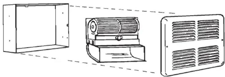
- Remove the grill by loosening and removing the two screws on the front panel.
- Remove the fan heater assembly by loosening the left mounting screw and removing the right mounting screw. The assembly will now slide to the right and drop out.
- Remove one 7/8" knockout and thread the supply wire into the wallbox. Use an approved strain relief bushing to prevent chaffing of the supply wires through the opening in the wallbox.
Be sure to allow for sheet rock or wall board in next step.
- Secure the ceiling wallbox to 2" x 4" frames or adequate support in the ceiling using the 4 holes provided on each side of the wallbox. The face of the wall can must be 12 " from the finished ceiling face.
- Replace the fan heater assembly by sliding it under the tab at the back top edge of the ceiling wallbox. Slide the assembly to the left so the slot engages the left screw head. Replace the right screw and tighten both assembly mounting screws.
- Attach the field groundwire to the green ground screw or green groundwire in wall can.
- Connect the supply wires to the leads from the heater.
- Replace the front grill and secure with the two screws provided.
The installation is now complete. The heater may be energized for use.
2007 WHFC.indd : 6/07
INSTALLATION INSTRUCTIONS
SAVE THESE INSTRUCTIONS
MODEL VOLTAGE WATTAGE BTUH WT
| WHFC2410 240 1000 or 500 3413 or 1706 8208 750 or 375 2650 or 1280 |
| WHFC2415 240 1500 or 750 5120 or 2650 8208 1125 or 562 3840 or 1920 |
| WHFC1210 120 1000 or 500 3413 or 1706 8 |
| WHFC1212 120 1200 or 600 4095 or 2047 8 |
| WHFC1215 120 1500 or 750 5120 or 2650 8 |
| OPTIONALWHSC-C Surface Mount Can 2 |
FEATURES
• 500 to 1500 Watts (1706 - 5120 BTU)
• 120 - 208 - 240 voltages available
• 95 CFM tangential (squirrel cage) blower
- Large 75 cubic inch wiring compartment for easy installation
• 20 gauge grill in white powder-coat fi nish
- Grill has large intake and outlet openings
• 20 gauge mounting wall can
- Elements are nickel chrome alloy coiled wire wrapped around a mica insulator
- Motor is vibration isolated by a shock absorbing rubber end cap
- Unique motor cooling system extends motor life
- Listed under UL2021 - standard for electric air heating

OPTIONS
- A special powder-coated can may be purchased for surface installation, model number WHSC-C.
WHFC - HEATER WIRING DIAGRAM
Two Element - Factory Wiring

flowchart
graph TD
    A["L1"] --> B["E1"]
    B --> C["E2"]
    C --> D["THEMOSTAT (OPTIONAL)"]
    D --> E["L2"]
    E --> F["L2 POWER SUPPLY"]
    G["FAN"] --> H["ELEMENT"]
    H --> I["TAG"]
    I --> J["L1"]
    K["LIMIT"] --> L["Limit"]
    M["LIMIT"] --> N["Limit"]
    O["LIMIT"] --> P["Limit"]
Single Element Factory Wiring

flowchart
graph TD
    A["FAN"] --> B["Capped Ends"]
    B --> C["E1"]
    C --> D["ELEMENT"]
    D --> E["L1"]
    E --> F["THERMOSTAT (OPTIONAL)"]
    F --> G["L2"]
    G --> H["L2 POWER SUPPLY"]
    I["LIMIT"] --> J["LIMIT"]
    J --> K["L2"]
    K --> L["THERMOSTAT (OPTIONAL)"]
    L --> M["L2 POWER SUPPLY"]
| MODEL | VOLTS | 2-Element Wattage | 1-Element Wattage |
| WHFC1210 | 120 | 1000 | 500 |
| WHFC1212 | 120 | 1200 | 600 |
| WHFC1215 | 120 | 1500 | 750 |
| WHFC2410 | 240 | 1000 | 500 |
| WHFC2415 | 240 | 1500 | 750 |
2007 WHFC.indd : 6/07
Brand : KING
Model : WHFC1215-W
Category : Heating