
Tour Indoor Cycle - Home trainer VirtuFit - Free user manual and instructions
Find the device manual for free Tour Indoor Cycle VirtuFit in PDF.


| Product Type | Indoor Cycle |
| Brand | VirtuFit |
| Model | Tour Indoor Cycle |
| Category | Home Trainer |
| Resistance System | Magnetic |
| Flywheel Weight | 8 kg |
| Max User Weight | 120 kg |
| Frame Material | Steel |
| Dimensions (L x W x H) | 100 x 50 x 120 cm |
| Product Weight | 25 kg |
| Power Supply | None (manual operation) |
| Display | Basic LCD (time, distance, speed, calories) |
| Pedals | SPD compatible with toe cages |
| Seat Adjustment | Vertical and horizontal |
| Handlebars | Multi-position with padding |
| Transport Wheels | Yes |
| Warranty | 2 years |
Frequently Asked Questions - Tour Indoor Cycle VirtuFit
User questions about Tour Indoor Cycle VirtuFit
0 question about this device. Answer the ones you know or ask your own.
Ask a new question about this device
Download the instructions for your Home trainer in PDF format for free! Find your manual Tour Indoor Cycle - VirtuFit and take your electronic device back in hand. On this page are published all the documents necessary for the use of your device. Tour Indoor Cycle by VirtuFit.
USER MANUAL Tour Indoor Cycle VirtuFit
Tour Indoor Cycle Spinbike
User manual
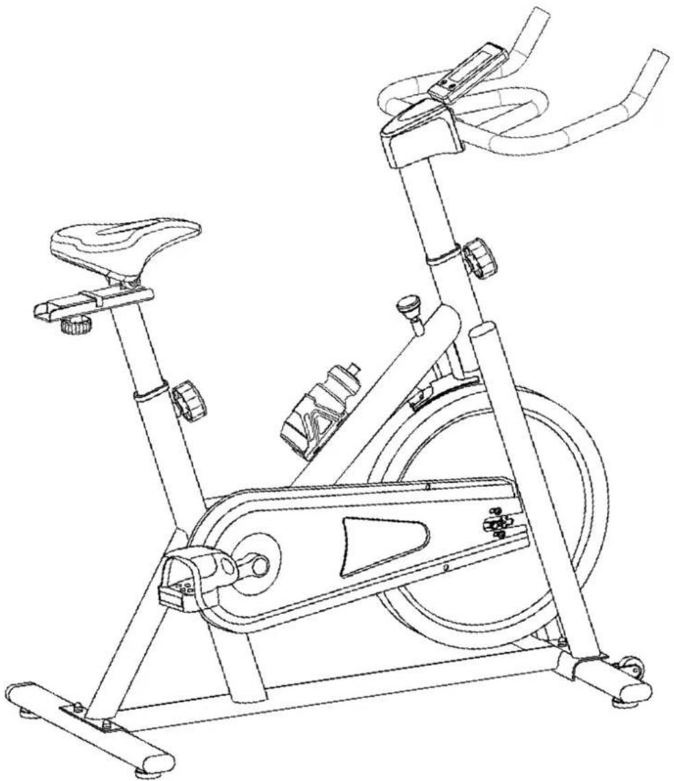
natural_image
Line drawing of a stationary exercise bike with visible legs, arms, and front wheel (no text or symbols)SAFETY INSTRUCTIONS SAFETY INSTRUCTIONS 3
ASSEMBLY INSTRUCTIONS ASSEMBLY INSTRUCTIONS 4 - 7
EXPLANATION RESISTANCEKNOB EXPLANATION RESISTANCEKNOB 8
PROBLEM SOLUTIONS PROBLEM SOLUTIONS 12
TRAINING INSTRUCTION STRAINING INSTRUCTIONS 13 - 14
EXPLODED DRAWING EXPLODED DRAWING 15
ONDERDELENLISTONDERDELENLIJST 16 - 17
WARNING:
Before beginning any exercise program consult your physician. This is especially important for people who are over 35 years old or who have pre-existing health problems. Read all instructions before using any fitness equipment. VirtuFit takes no responsibility for injuries or material damage caused by using this product. be sure to read the entire manual before you assemble or operate your machine, in particular, note the following safety precautions
ATTENION
- Check all the screws, nuts and other connections before using the machine for the first time and ensure that the trainer is in the safe condition.
- Set up the machine in a dry level place and leave it away from moisture and water.
- Place a suitable base (e.g. rubber mat, wooden board etc.) beneath the machine in the area of assembly to avoid dirt.
- Before beginning training, remove all objects within a radius of 2 meters from the machine.
- DO NOT use aggressive cleaning articles to clean the machine, Only use the supplied tools or suitable tools of your own to assemble the machine or repair any parts of machine. Remove drops of sweat from the machine immediately after finishing training.
- Your health can be affected by incorrect or excessive training. Consult a doctor before beginning a training program. He can define the maximum setting (Pulse, Duration of training etc) to which you may train yourself and can get precise information during training. This machine is not suitable for therapeutic purpose.
- Only do training on the machine when it is in correct working way. Use only original spare parts for any necessary repairs.
- This machine can be used for only one person's training at a time.
- Wear training clothes and shoes which are suitable for fitness training with the machine. Your training shoes should be appropriate for the trainer.
- If you have a feeling of dizziness, sickness or other abnormal symptoms, please stop training and consult a doctor asap.
- People such as children should only use the machine in the presence of another person who can give aid and advice.
- The power of the machine increases with increasing the speed, and the reverse. The machine is equipped with adjustable knob which can adjust the resistance. Reduce the resistance by turning the adjusting clockwise. Increase the resistance by turning the adjusting knob setting counter clockwise.
Preparation:
- Before assembling make sure that you will have enough space around the item;
- Use the present tooling for assembling;
- Some screws and bolts are already pre-assembled in the spinbike;
- Some parts may be hidden in the box or in the styrofoam. Take a good look at this.
STEP 1

- Lock the Front Stabilizer (03) to the Main Frame (01) with two sets of ∅8 Flat Washer (20), M8 Domed Nut (19) and M8*42 Carriage Bolt (14);
- Lock the Rear Stabilizer (02) to the Main Frame (01) with two sets of ∅8 Flat Washer (20), M8 Domed Nut (19) and M8*42 Carriage Bolt (14).
STEP 2

- Insert the Vertical Seat Post (04) into the seat post tube of the Main Frame. You will have to slacken the Knob (23) and pull the knob back. Then select the desired height. Release the knob and retighten the knob.;
• The Seat Post (05) is fixed on the Vertical Seat Post (04) with the Knob (35) and the Flat Washer (36).;
• The Seat (08) is fixed on the Seat Post (05) with three sets of Flat Washer (20) and Lock Nut (17); - Tighten the bolts on the left and right under the saddle so that the saddle is locked on the seat post.
STEP 3

- Insert the Handlebar Post (6) into the handlebar post tube of the main frame. You will have to slacken the Knob (23) and pull the knob back. Then select the desired height. Release the knob and retighten the knob;
- The Handlebar (7) and the Computer Holder (78) are fixed on the Handlebar Post (6) with four sets of Bolt (33) and Spring Washer (32).;
- Attach the Computer (67) to the Computer Holder (78). Make sure cable (A1) is connected to cable (A2);
- Tilt and bend the bracket slightly to get a good viewing angle on the display. The metal of the bracket can be bend. A computer that is too upright can cause that the display is not easy to read.
ATTENTION: You should fix the handlebar tightly.
STEP 4

- The Pedals (9L & 9R) are marked "L" and "R" - Left and Right. Connect them to their appropriate crank arms. The right crank arm is on the right-hand side of the cycle as you sit on it. Note that the Right pedal should be threaded on clockwise and the Left pedal anti clockwise. Turn the pedal first by hand gently and place the pedal on the crankset, do not force. As last use tool to tighten extra firmly;
- Level the spinbike by turning the adjusters in/out under the stabilizers.
natural_image
Line drawing of an exercise bike with labeled component '37' and motion arrow (no text or symbols beyond label)- To increase resistance (requiring more strength to pedal), turn the Emergency Brake & Resistance Control Knob (37) to the right.
- To decrease resistance (requiring less strength to pedla), turn the Emergency Brake & Resistance Control Knob (pt.37) to the left.
- The Emergency Brake & Resistance Control Knob can be used as the Emergency Brake. When you want the flywheel to stop turning, you must firmly press down the Emergency Brake & Tension Control Knob (37).
CONSOLE

KNOB FUNCTION
KNOB DESCRIPTION
| SET | - Press SET key to increase value. Press and hold the key to increase value faster.- TIME setting range: 00:00~99:00 (Each increment is 1:00).- CAL setting range: 0~9990 (Each increment is 10).- DIST setting range: 0.00~99.50 (Each increment is 0.5).- PULSE setting range: 0-30~230 (Each increment is 1). |
| MODE/RESET | - Choose each function by pressing MODE/RESET key.- Press and hold MODE/RESET key for 2 seconds to reset all functions. |
DISPLAY FUNCTION
| DISPLAY DESCRIPTION | |
| SCAN | - In SCAN mode, press MODE/ENTER key to choose functions.- Automatically scan through each mode in sequence every 6 seconds.- The sequence of display when press MODE/ENTER key : TIME-DIST-CALPULSE-RPM/SPEED |
| SPEED | - Range 0.0 ~ 99.9- Without any signal being transmitted into the monitor for 4 seconds during workout, SPEED will display "0.0" |
| RPM | - Range 0 ~ 999- Without any signal being transmitted into the monitor for 4 seconds during workout, RPM will display "0" |
| TIME | - Without setting the target value, time will count up.- When setting the target value, time will count down from your target time to 0 and alarm will sound or flash.-Without any signal being transmitted into the monitor for 4 seconds during workout, time will STOP- Range 0:00 ~ 99:59 |
| DISTANCE | - Without setting the target value, distance will count up.-When setting the target value, distance will count down from your target distance to 0 with an alarm sound or flash.- Range 0.00~99.99 |
| CALORIES | - Without setting the target value, calorie will count up.- When setting the target value, calories will count down from your target calorie to 0 with an alarm sound or flash.- Range 0~9999 |
| PULSE | - Current pulse will display after 6 seconds when detected by the console.- Without any pulse signal for 6 seconds, console will display "P".- Pulse alarm will sound when current pulse is over the target pulse.- Range 0-30~230 BPM |
OPERATION PROCEDURE
POWER ON
- LCD will display all segments shown as this picture on the right
POWER OFF
- Without any signal being transmitted into the monitor for 4 minutes the monitor will enter SLEEP mode.

OPERATION
WORKOUT SETTINGS:
- Press MODE/RESET key to select the function of TIME, DISTANCE, CALORIES and PULSE. Use SET Key for setting and press MODE/RESET key for confirmation.
- For instance the time set-up, when the time value is blinking, you can use SET Key to adjust the number. Press MODE/RESET key for confirmation and skip to next set-up. The set-up of DISTANCE, CALORIES and PULSE is the same as TIME set-up.
- Once the workout begins and the console picks up the exercise signal, the value of SPEED/RPM, TIME, DST and CAL will count up on the display.
PROBLEM SOLUTIONS
- When the display of the LCD is less bright, you can adjust the viewing angle by pressing the console bracket slightly forward. The metal can be bend. If this doesn't work, the battery must be replaced.
- If there is no signal while pedalling, check if the cable of the console is properly connected. Does the display still show no values? Then push the sensor a bit further into the chain. The sensor is located on the inside of the chain guard at the left pedal.
- Beeps the resistance while increasing? The felt pad of the brake system may be slightly dehydrated. Coat a small amount of Vaseline on the felt pad.
A successful exercise program consists of a warm-up, aerobic exercise, and a cool-down. Do the entire program at least two and preferably three times a week, resting for a day between workouts. After several months, you can increase your workouts to four or five times per week.
WARMING UP
This stage helps get the blood flowing around the body and the muscles working properly. It will also reduce the risk of cramp and muscle injury. It is advisable to do a few stretching exercises as shown below. Each stretch should be held for approximately 30 seconds, do not force or jerk your muscles into a stretch - if it hurts, STOP.

TOE TOUCH

INNER THIGH STRETCH

ACHILLES STRETCH

natural_image
Line drawing of a person performing a seated leg stretch (no text or symbols)HAMSTRING STRETCH

natural_image
Line drawing of a person performing a stretching exercise with arms raised (no text or symbols)SIDE STRETCH
THE EXERCISE PHASE
This is the stage where you put the effort in. After regular use, the muscles in your legs will become Stronger. Work to your but it is very important to maintain a steady tempo throughout. The rate of work should be sufficient to raise your heart beat into the target zone shown on the graph below.
THE EXERCISE PHASE

line
| AGE | HEART RATE | | --- | --- | | 20 | 160 | | 40 | 120 | | 75 | 90 |This stage is to let your Cardio-vascular System and muscles wind down. This is a repeat of the warm up exercise e.g. reduce your tempo, continue for approximately 5 minutes. The stretching exercises should now be repeated, again remembering not to force or jerk your muscles into the stretch.
As you get fitter you may need to train longer and harder. It is advisable to train at least three times a week, and if possible space your workouts evenly throughout the week.
Muscle Toning
To tone muscle while on your SPINNING BIKE you will need to have the resistance set quite high. This will put more strain on our leg muscles and may mean you cannot train for as long as you would like. If you are also trying to improve your fitness you need to alter your training program. You should train as normal during the warm up and cool down phases, but towards the end of the exercise phase you should increase resistance, making your legs work harden than normal. You may have to reduce your speed to keep your heart rate in the target zone.
Weight Loss
The important factor here is the amount of effort you put in. The harder and longer you work the more calories you will burn. Effectively this is the same as if you were training to improve your fitness, the difference is the goal.
Use
The tension control knob allows you to alter the resistance of the pedals. A high resistance makes it more difficult to pedal, a low resistance makes it easier. For the best results set the tension while the bike is in use.
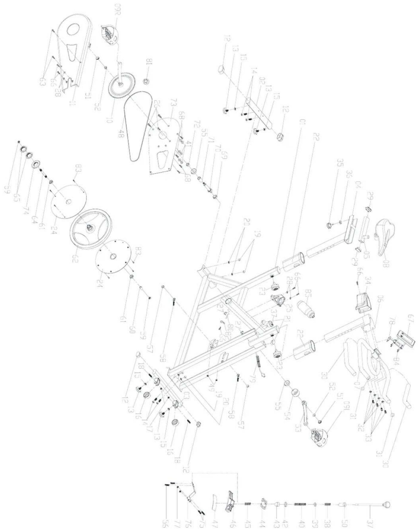
| # DESCRIPTION QTY | |
| 1 Main frame 1 | |
| 2 Rear Stabilizer 1 | |
| 3 Front Stabilizer 1 | |
| 4 Vertical Seatpost 1 | |
| 5 Seat Post 1 | |
| 6 Handlebar Post 1 | |
| 7 Handlebar 1 | |
| 8 Seat PVC98-2 1 | |
| 9 Pedal L/R JD-301 (9/16") 1 | |
| 10 Crank 170*48 | 1 |
| 11 Outer Chain Cover 655*268*43 | 1 |
| 12 End Cap 70*30*1.5 | 4 |
| 13 Stopper ∅35*37/(M8X20 | 4 |
| 14 Carriage Bolt M8*42 | 4 |
| 15 Nut M8 | 4 |
| 16 Wheel ∅50*23 | 2 |
| 17 Lock Nut 1 M8*40 | 5 |
| 18 Bolt 1 M8*40 | 2 |
| 19 Domed Nut M8 (H-16mm) | 4 |
| 20 Flat Washer | 7 |
| 21 End Cap 1 50*25*1.5 | 2 |
| 22 Plastic Sleeve 60*30*1.5 | 2 |
| 23 Adjustable Knob M16*1.5*20 | 2 |
| 24 Kettle ∅73*215 | 1 |
| 25 Kettle Holder ∅6 | 1 |
| 26 Screw 1 ST4.2X32 | 3 |
| 27 Plastic Plug ∅14*14 | 2 |
| 28 Flat Washer | 4 |
| 29 End cap 2 40*20*1.5 | 2 |
| 30 Foam grip ∅23* ∅33*465 | 2 |
| 31 End cap 3 ∅25*1.5 | 2 |
| # DESCRIPTION QTY | |
| 32 Spring Washer | 4 |
| 33 Bolt 2 M8*15 | 4 |
| 34 Handlebar Cover 115*89*75 | 1 |
| 35 Locking Knob ∅52*47 (M8X15) | 1 |
| 36 Flat washer 1 ∅32*∅8.2*2 | 1 |
| 37 Knob ∅40*160 | 1 |
| 38 Spring 1 ∅1.8X40 | 1 |
| 39 Fixing nut 15X15X4 | 1 |
| 40 Spring 2 ∅1.0X55 | 1 |
| 41 Plastic pipe ∅20* ∅9*3 | 6 |
| 42 Flat Washer 2 ∅14* ∅6*t2.5 | 1 |
| 43 Domed Nut 2 M6 | 1 |
| 44 Spring cover 32*23*2 | 1 |
| 45 Spring 3 ∅22 | 1 |
| 46 Plastic frame 200*47*30 | 1 |
| 47 Woolly Block 113*25*6 | 1 |
| 48 Chain P=12.7 106 | 1 |
| 49 Nut M6 | 2 |
| 50 Little plastic ∅16*25 | 1 |
| 51 Crank End Cap ∅23*7.5 | 2 |
| 52 Fixing Nut 2 M10*1.0 | 2 |
| 53 Left Crank 170*43 | 1 |
| 54 Crank Cover ∅56*28 | 1 |
| 55 Bearing 6203ZZ | 2 |
| 56 Bolt 3 M5*10 | 2 |
| 57 Fixing Nut 1 M10*1.25 | 2 |
| 58 Fixing Bolt M6*55 | 2 |
| 59 Fixing Nut 2 M10*1.0 | 2 |
| 60 Fixing Tube ∅13.6* ∅10.1*36 | 1 |
| 61 Bearing 6000ZZ | 2 |
| 62 Flywheel 18KG | 1 |
| 63 Screw 2 ST4.2X9.5 F 2 | |
| 64 Flywheel shaft ∅10*160 1 | |
| 65 Lock Nut M33*1*4 2 | |
| 66 Screw 3 ST4.2X19 6 | |
| 67 Computer X-3574 1 | |
| 68 Screw 4 ST4.2*16 4 | |
| 69 Fixing Nut ∅28*M20*1 1 | |
| 70 Axis ∅20*146 1 | |
| 71 Long Fixing Tube ∅22* ∅17.05*41 1 | |
| 72 Short Fixing Tube ∅22* ∅17.05*11 1 | |
| 73 Inner Chain Cover 467*266*11 | 1 |
| 74 Chain wheel A7K-16 1/2"*1.8" 16T 1 | |
| 75 Bolt 4 M5*30 | 2 |
| 76 Spring ∅1.0 | 1 |
| 77 Lock Nut M5*30 | 2 |
| 78 Computer holder ∅2.5 | 1 |
| 79 Sensing Line L=1400 | 1 |
| 80 Sensor SR-212 | 1 |
| 81 Magnet c-02Z | 1 |
| 82 Sensor Holder LTF8163 | 7 |
virtufit
Brand : VirtuFit
Model : Tour Indoor Cycle
Category : Home trainer