PEA-M100GAA - Air Conditioning MITSUBISHI - Free user manual and instructions
Find the device manual for free PEA-M100GAA MITSUBISHI in PDF.

| Type | Ceiling Cassette Air Conditioner |
| Cooling Capacity | 100,000 BTU/h (approx. 29 kW) |
| Heating Capacity | 112,000 BTU/h (approx. 32.8 kW) |
| Power Supply | 380-415 V, 3-phase, 50/60 Hz |
| Refrigerant | R410A |
| Dimensions (Indoor Unit) | 840 x 840 x 300 mm (WxHxD) |
| Weight (Indoor Unit) | Approx. 55 kg |
| Dimensions (Outdoor Unit) | 950 x 1,350 x 350 mm (WxHxD) |
| Weight (Outdoor Unit) | Approx. 120 kg |
| Airflow Rate (High) | 2,500 m³/h |
| Sound Level (Indoor) | 35-45 dB(A) |
| Sound Level (Outdoor) | 55-60 dB(A) |
| Functions | Cooling, Heating, Fan, Dehumidification, Auto Mode, Timer, Sleep Mode, I-Save |
| Control | Wired Remote Controller (optional wireless) |
| Filter | Washable mesh filter |
| Maintenance | Clean filter every 2 weeks; professional service recommended annually |
| Safety | Disconnect power before cleaning; do not block air intake/outlet |
| Repair & Spare Parts | Contact authorized Mitsubishi dealer for genuine parts |
| Energy Efficiency | EER: 3.2 (approx.) |
| Warranty | 2 years standard (check local) |
Frequently Asked Questions - PEA-M100GAA MITSUBISHI
User questions about PEA-M100GAA MITSUBISHI
0 question about this device. Answer the ones you know or ask your own.
Ask a new question about this device
Download the instructions for your Air Conditioning in PDF format for free! Find your manual PEA-M100GAA - MITSUBISHI and take your electronic device back in hand. On this page are published all the documents necessary for the use of your device. PEA-M100GAA by MITSUBISHI.
USER MANUAL PEA-M100GAA MITSUBISHI
PEA-M100, 125, 140GAA
OPERATION MANUAL
FOR USER
For safe and correct use, please read this operation manual thoroughly before operating the air-conditioner unit.
English
Contents
- Safety Precautions ...... 2
- Parts Names....3
- Operation....7
-
Timer....10
-
Emergency Operation for Wireless Remote-controller (option)....10
- Trouble Shooting 11
- Specifications ....12
Note:
The phrase “Wired remote controller” in this operation manual refers only to the PAR-33MAA. If you need any information for other remote controller, please refer to the instruction book included with the remote controller.
1. Safety Precautions
▶ Before operating the unit, make sure you read all the “Safety precautions”.
▶ “Safety precautions” lists important points about safety. Please be sure to follow them.
MEANINGS OF SYMBOLS ON THE UNIT
| WARNING(Risk of fire) | This symbol is only for R32 refrigerant. The type of the refrigerant used is written on the nameplate on the outdoor unit.R32 refrigerant is flammable. If the refrigerant leaks, or comes in contact with fire or parts that generate heat, it may create harmful gas and pose a risk of fire. | |
| Read the OPERATION MANUAL carefully before operation. | ||
| Service personnel are required to carefully read the OPERATION MANUAL and INSTALLATION MANUAL before operation. | ||
| Further information is available in the OPERATION MANUAL, INSTALLATION MANUAL, and the like. | ||
Symbols used in the text
⚠ Warning:
Describes precautions that should be observed to avoid the risk of injury or death to the user.
Caution:
Describes precautions that should be observed to prevent damage to the unit.
Symbols used in the illustrations
○ : Indicates an action that must be avoided.
! : Indicates that important instructions must be followed.
↓: Indicates a part which must be grounded.
A: Beware of electric shock. (This symbol is displayed on the main unit label.)
⚠ Warning:
Carefully read the labels affixed to the main unit.
⚠ Warning:
• These appliances are not accessible to the general public.
- The unit must not be installed by the user. Ask the dealer or an authorized company to install the unit. If the unit is installed improperly, water leakage, electric shock or fire may result.
- Do not stand on, or place any items on the unit.
- This air conditioner is NOT intended for use by children or infirm persons without supervision.
- Young children must be supervised to ensure that they do not play with the air conditioner.
- When installing, relocating, or servicing the air conditioner, use only the specified refrigerant written on the outdoor unit to charge the refrigerant lines. Do not mix the refrigerant with any other refrigerant, and do not allow air to remain in the lines.
- If air is mixed with the refrigerant, then it may cause abnormal high pressure in the refrigerant lines, resulting in an explosion and other hazards.
- The use of any refrigerant other than that specified for the system will cause mechanical failure, system malfunction, or unit breakdown. In the worst case, this could lead to a serious impediment to securing product safety.
- It may also be in violation of applicable laws.
- MITSUBISHI ELECTRIC CORPORATION cannot be held responsible for malfunctions or accidents resulting from the use of the wrong type of refrigerant.
- This indoor unit should be installed in a room which is equal to or larger than the floor space specified in the outdoor unit installation manual. Refer to the outdoor unit installation manual.
- Only use means recommended by the manufacturer to accelerate the defrosting process or to clean.
- This indoor unit shall be stored in a room that has no continuously-operating ignition device such as open flame, gas appliance, or electrical heater.
- Do not pierce a hole in or burn this indoor unit or refrigerant lines.
- Be aware that the refrigerant may be odour-free.
- Do not splash water over the unit and do not touch the unit with wet hands. An electric shock may result.
- Do not spray combustible gas close to the unit. Fire may result.
- Do not place a gas heater or any other open-flame appliance where it will be exposed to the air discharged from the unit. Incomplete combustion may result.
- Do not remove the front panel or the fan guard from the outdoor unit when it is running. You could be injured if you touch rotating, hot or high-voltage parts.
- Never insert fingers, sticks etc. into the intakes or outlets, otherwise injury may result, since the fan inside the unit rotates at high speed. Exercise particular care when children are present.
- If you detect odd smells, stop using the unit, turn off the power switch and consult your dealer. Otherwise, a breakdown, electric shock or fire may result.
- When you notice exceptionally abnormal noise or vibration, stop operation, turn off the power switch, and contact your dealer.
- Do not over-cool. The most suitable inside temperature is one that is within 5^ of the outside temperature.
- Do not leave handicapped people or infants sitting or standing in the path of the airflow from the air-conditioner. This could cause health problems.
Caution:
- Do not use any sharp object to push the buttons, as this may damage the remote controller.
- Do not twist or tug on the remote controller cord as this may damage the remote controller and cause malfunction.
- Never remove the upper case of the remote controller. It is dangerous to remove the upper case of the remote controller and touch the printed circuit boards inside. Doing so can result in fire and failure.
- Never wipe the remote controller with benzene, thinner, chemical rags, etc. Doing so can result in discoloration and failure. To remove heavy stains, soak a cloth in neutral detergent mixed with water, wring it out thoroughly, wipe the stains off, and wipe again with a dry cloth.
In case of failure
Warning:
- Never remodel the air conditioner. Consult your dealer for any repair service. Improper repair work can result in water leakage, electric shock, fire, etc.
- If the remote controller displays an error indication, the air conditioner does not run, or there is any abnormality, stop operation and contact your dealer. Leaving the unit as it is under such conditions can result in fire or failure.
- If the power breaker is frequently activated, get in touch with your dealer. Leaving it as it is can result in fire or failure.
- If the refrigeration gas blows out or leaks, stop the operation of the air conditioner, thoroughly ventilate the room, and contact your dealer. Leaving the unit as it is can result in accidents due to oxygen deficiency.
Disposing of the unit
Warning:
When you need to dispose of the unit, consult your dealer. If pipes are removed incorrectly, refrigerant (fluorocarbon gas) may blow out and come into contact with your skin, causing injury. Releasing refrigerant into the atmosphere also damages the environment.
- Never block or cover the indoor or outdoor unit's intakes or outlets. Tall items of furniture underneath the indoor unit, or bulky items such as large boxes placed close to the outdoor unit will reduce the unit's efficiency.
- Do not direct the airflow at plants or caged pets.
- Ventilate the room frequently. If the unit is operated continuously in a closed room for a long period of time, the air will become stale.
When the air conditioner is not to be used for a long time
- If the air conditioner is not to be used for a long time due to a seasonal change, etc., run it for 4 - 5 hours with the air blowing until the inside is completely dry. Failing to do so can result in the growth of unhygienic, unhealthy mold in scattered areas throughout the room.
- When it is not to be used for an extended time, keep the [power supply] turned OFF.
If the power supply is kept on, several watts or several tens of watts will be wasted. Also, the accumulation of dust, etc., can result in fire.
- Keep the power switched ON for more than 12 hours before starting operation. Do not turn the power supply OFF during seasons of heavy use. Doing so can result in failure.
2. Parts Names
■ Indoor Unit
| PEA-M·GAA | |
| Fan steps 2 steps | |
| Vane – | |
| Louver – | |
| Filter – | |
| Filter cleaning indication – |
PEA-M·GAA
Ceiling Concealed
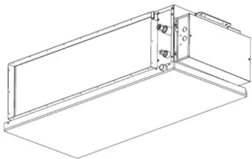
natural_image
Technical line drawing of a mechanical assembly with mounting brackets and housing (no text or symbols)
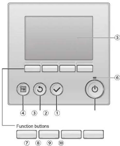
■ Wired Remote Controller
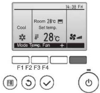
Controller interface
text_image
Function buttons ① ② ③ ④ ⑤ ⑥The functions of the function buttons change depending on the screen.
Refer to the button function guide that appears at the bottom of the LCD for the functions they serve on a given screen.
When the system is centrally controlled, the button function guide that corresponds to the locked button will not appear.
text_image
Main display Main menu Cool Room 28° Set temp. 28° Main Temp. Fan + ⑦ ⑧ ⑨ ⑩ ⑦ ⑧ ⑨ ⑩ Function guide Main Main menu V/1 Vane-Lower-Vent. (Lossray) High power Timer Weekly timer OU silent mode Main menu Cursor Guide ← > ⑦ ⑧ ⑨ ⑩① [ON/OFF] button
Press to turn ON/OFF the indoor unit.
② [SELECT] button
Press to save the setting.
③ [RETURN] button
Press to return to the previous screen.
④ [MENU] button
Press to bring up the Main menu.
⑤ Backlit LCD
Operation settings will appear.
When the backlight is off, pressing any button turns the backlight on and it will stay lit for a certain period of time depending on the screen.
When the backlight is off, pressing any button turns the backlight on and does not perform its function. (except for the [ON/OFF] button)
⑥ ON/OFF lamp
This lamp lights up in green while the unit is in operation. It blinks while the remote controller is starting up or when there is an error.
⑦ Function button [F1]
Main display: Press to change the operation mode.
Main menu: Press to move the cursor down.
⑧ Function button [F2]
Main display: Press to decrease temperature.
Main menu: Press to move the cursor up.
⑨ Function button [F3]
Main display: Press to increase temperature.
Main menu: Press to go to the previous page.
⑩ Function button [F4]
Main display: Press to change the fan speed.
Main menu: Press to go to the next page.
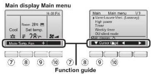
Display
The main display can be displayed in two different modes: "Full" and "Basic". The factory setting is "Full". To switch to the "Basic" mode, change the setting on the Main display setting. (Refer to operation manual included with remote controller.)
* All icons are displayed for explanation.
text_image
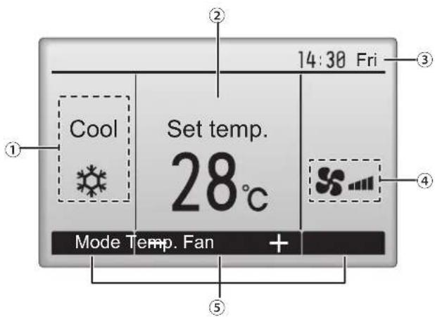
14:30 Fri Room 28°C Set temp. 28°C Cool Mode Temp. Fan ③ ② ④ ⑤
text_image
14:30 Fri ② Cool Set temp. 28°C Mode Temp. Fan + ③ ④ ⑤① Operation mode
Indoor unit operation mode appears here.
② Preset temperature
Preset temperature appears here.
③ Clock (See the Installation Manual.)
Current time appears here.
④ Fan speed
Fan speed setting appears here.
⑤ Button function guide
Functions of the corresponding buttons appear here.

Appears when the ON/OFF operation is centrally controlled.

Appears when the operation mode is centrally controlled.

Appears when the preset temperature is centrally controlled.

Appears when the filter reset function is centrally controlled.

Indicates when filter needs maintenance.
⑪ Room temperature (See the Installation Manual.)
Current room temperature appears here.

Appears when the buttons are locked.

Appears when the On/Off timer, Night setback, or Auto-off timer function is enabled.
appears when the timer is disabled by the centralized control system.

Appears when the Weekly timer is enabled.

Appears while the units are operated in the energy-save mode. (Will not appear on some models of indoor units)

Appears while the outdoor units are operated in the silent mode.

Appears when the built-in thermistor on the remote controller is activated to monitor the room temperature (⑪).

It appears when the thermistor on the indoor unit is activated to filter the room temperature.

Appears when the units are operated in the energy-save mode with 3D i-see Sensor.

Indicates the vane setting.

Indicates the louver setting.

Indicates the ventilation setting.

Appears when the preset temperature range is restricted.
Most settings (except ON/OFF, mode, fan speed, temperature) can be made from the Menu screen.
(Refer to operation manual included with remote controller.)
■ Wireless Remote-Controller (option)
text_image
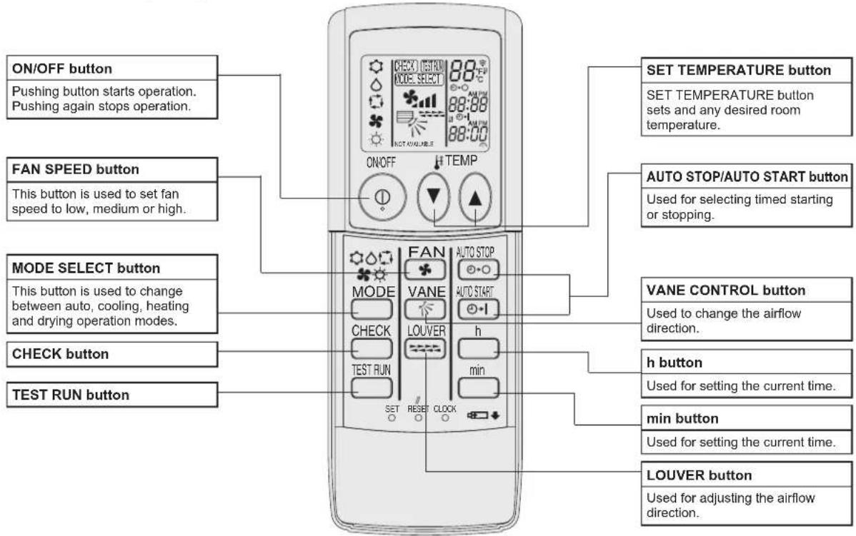
ON/OFF button Pushing button starts operation. Pushing again stops operation. FAN SPEED button This button is used to set fan speed to low, medium or high. MODE SELECT button This button is used to change between auto, cooling, heating and drying operation modes. CHECK button TEST RUN button SET TEMPERATURE button SET TEMPERATURE button sets and any desired room temperature. AUTO STOP/AUTO START button Used for selecting timed starting or stopping. VANE CONTROL button Used to change the airflow direction. h button Used for setting the current time. min button Used for setting the current time. LOUVER button Used for adjusting the airflow direction.■ When using the wireless remote controller, point it towards the receiver on the indoor unit.
If the remote controller is operated within approximately two minutes after power is supplied to the indoor unit, the indoor unit may beep twice as the unit is performing the initial automatic check.
The indoor unit beeps to confirm that the signal transmitted from the remote controller has been received. Signals can be received up to approximately 7 meters in a direct line from the indoor unit in an area 45^ to the left and right of the unit. However, illumination such as fluorescent lights and strong light can affect the ability of the indoor unit to receive signals.
If the operation lamp near the receiver on the indoor unit is flashing, the unit needs to be inspected. Consult your dealer for service.
■ Handle the remote controller carefully! Do not drop the remote controller or subject it to strong shocks. In addition, do not get the remote controller wet or leave it in a location with high humidity.
■ To avoid misplacing the remote controller, install the holder included with the remote controller on a wall and be sure to always place the remote controller in the holder after use.
Battery installation/replacement
- Remove the top cover, insert two AAA batteries, and then install the top cover.
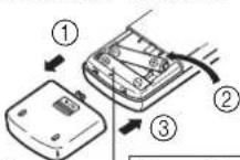
Top cover
Two AAA batteries Insert the negative (−) end of each battery first. Install the batteries in the correct directions (+, −)!
- Press the Reset button.
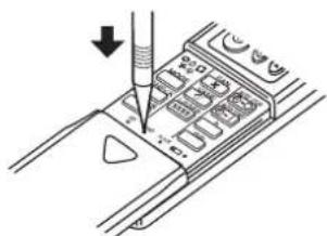
natural_image
Diagram of a device with a screwdriver inserted into a control panel (no text or symbols visible)Press the Reset button with an object that has a narrow end.
3. Operation
■ About the operation method, refer to the operation manual that comes with each remote controller.
3.1. Turning ON/OFF
3.1.1. For wired remote controller
[ON] [OFF]
natural_image
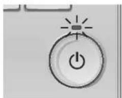
Simple icon of a power button with a light indicator and sparkles (no text or symbols)Press the [ON/OFF] button. The ON/OFF lamp will light up in green, and the operation will start.
natural_image
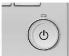
Simple icon of a power button with a minus sign, no text or symbols presentPress the [ON/OFF] button again. The ON/OFF lamp will come off, and the operation will stop.
■ Operation status memory
| Remote controller setting | |
| Operation mode Operation mode before the power was turned off | |
| Preset temperature Preset temperature before the power was turned off | |
| Fan speed | Fan speed before the power was turned off |
■ Settable preset temperature range
| Operation mode | Preset temperature range |
| Cool/Dry | 19 – 30 °C |
| Heat | 17 – 28 °C |
| Auto | 19 – 28 °C |
| Fan/Ventilation | Not settable |
3.1.2. For wireless remote controller
[ON]
■ Press the ON/OFF button ①.
Note:
- When the unit is restarted, initial settings are as follows.
| Remote Controller settings | |||
| Mode Last operation mode | |||
| Temperature setting Last set temperature | |||
| Fan speed Last set fan speed | |||
| Airflow up/down Mode | COOL or DRY Horiz. outlet | ||
| HEAT Last setting | |||
| FAN Horiz. outlet | |||
[OFF]
■ Press the ON/OFF button ① again.
![MITSUBISHI PEA-M100GAA - [OFF] - 1](/content/2026/05/980157/images/b77e4cc9c76332de196250e74f214e4f9d99b6f4228c9fe3b497755a3eea7512.jpg)
text_image
2 3 4 1 25 9:00 ON/OFF TEMP FAN AUTO STOP MODE VANE AUTO START CHECK LOWER h TEST RUN min SET RESET CLOCK(option)
Note:
Even if you press the ON/OFF button immediately after shutting down the operation is progress, the air conditioner will not start for about three minutes. This is to prevent the internal components from being damaged.
3.2. Mode select
3.2.1. For wired remote controller
text_image
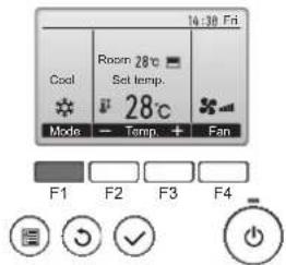
14:30 Fri Cool Room 28°C Set temp. 28°C Mode - Temp. + Fan F1 F2 F3 F4Press the [F1] button to go through the operation modes in the order of "Cool", "Dry", "Fan", "Auto", and "Heat". Select the desired operation mode.
text_image
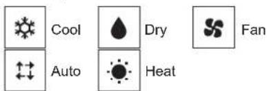
Cool Dry Fan Auto Heat• Operation modes that are not available to the connected indoor unit models will not appear on the display.
What the blinking mode icon means
The mode icon will blink when other indoor units in the same refrigerant system (connected to the same outdoor unit) are already operated in a different mode. In this case, the rest of the unit in the same group can only be operated in the same mode.
3.2.2. For wireless remote controller
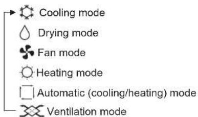
■ Press the operation mode (☐♣◇◇) button ② and select the operation mode ②.
text_image
Cooling mode Drying mode Fan mode Heating mode Automatic (cooling/heating) mode Ventilation modeOnly indicated on the following condition Wired remote controller used LOSSNAY connected
3. Operation
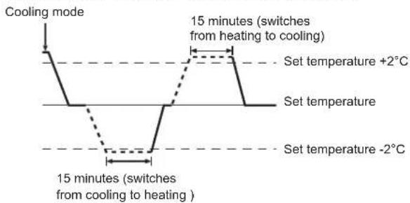
Automatic operation
According to a set temperature, cooling operation starts if the room temperature is too hot and heating operation starts if the room temperature is too cold.
During automatic operation, if the room temperature changes and remains 2 °C or more above the set temperature for 15 minutes, the air conditioner switches to cooling mode. In the same way, if the room temperature remains 2 °C or more below the set temperature for 15 minutes, the air conditioner switches to heating mode.
text_image
Cooling mode 15 minutes (switches from heating to cooling) Set temperature +2°C Set temperature Set temperature -2°C 15 minutes (switches from cooling to heating)Because the room temperature is automatically adjusted in order to maintain a fixed effective temperature, cooling operation is performed a few degrees warmer and heating operation is performed a few degrees cooler than the set room temperature once the temperature is reached (automatic energy-saving operation).
3.3. Temperature setting
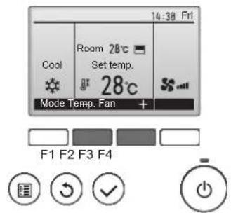
3.3.1. For wired remote controller
text_image
14:30 Fri Cool Room 28°C Set temp. 28°C Mode Temp. Fan + F1 F2 F3 F4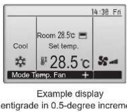
text_image
14:39 Fri Room 28.5°C Set temp. 28.5°C Mode Temp. Fan + Example display entigrade in 0.5-degree incremePress the [F2] button to decrease the preset temperature, and press the [F3] button to increase.
- Refer to the table on page 7 for the settable temperature range for different operation modes.
- Preset temperature range cannot be set for Fan/Ventilation operation.
- Preset temperature will be displayed either in Centigrade in 0.5- or 1-degree increments, or in Fahrenheit, depending on the indoor unit model and the display mode setting on the remote controller.
3.3.2. For wireless remote controller
▶ To decrease the room temperature:
Press 📋 button③ to set the desired temperature.
The selected temperature is displayed 3.
• Each time you press the button, the temperature value decreases by 1 °C.
▶ To increase the room temperature:
Press ▲ button③ to set the desired temperature.
The selected temperature is displayed 3.
• Each time you press the button, the temperature value decreases by 1 °C.
• Available temperature ranges are as follows:
Cooling/Drying: 19 - 30 °C
Heating: 17 - 28 °C
Automatic: 19 - 28 °C
- The display flashes either 8 °C - 39 °C to inform you if the room temperature is lower or higher than the displayed temperature.
3.4. Fan speed setting
3.4.1. For wired remote controller
text_image
14:30 Fri Cool Room 28°C Set temp. 28°C Mode Temp. Fan + F1 F2 F3 F4Press the [F4] button to go through the fan speeds in the following order.
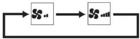
flowchart
graph LR
    A["Start"] --> B["Step 1"]
    B --> C["Step 2"]
    C --> D["End"]
3.4.2. For wireless remote controller
■ Press ④ button to select a desired fan speed.
• Each time you press the button, available options change with the display 4 on the remote controller, as shown below.
| Fan speed | Remote controller display | |
| Low High | ||
| 2-stage | ||
Notes:
- In the following cases, the actual fan speed generated by the unit will differ from the speed shown the remote controller display. 1. While the display is in "STAND BY" or "DEFROST" states.
- When the temperature of the heat exchanger is low in the heating mode.
(e.g. immediately after heating operation starts) - In HEAT mode, when room temperature is higher than the temperature setting.
- When the unit is in DRY mode.
3. Operation
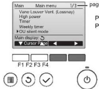
3.5. Ventilation (For wired remote controller)
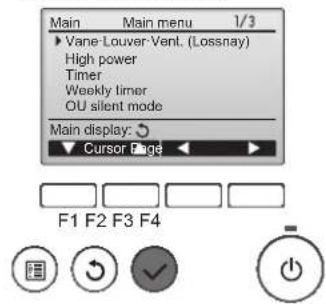
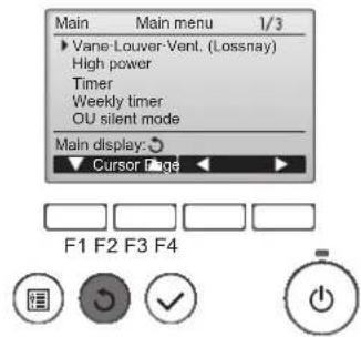
3.5.1. Navigating through the Main menu
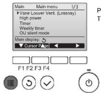
text_image
Main Main menu 1/3 ►Vane Louver Vent. (Lossnay) High power Timer Weekly timer OU silent mode Main display: ▼ Cursor Page F1 F2 F3 F4
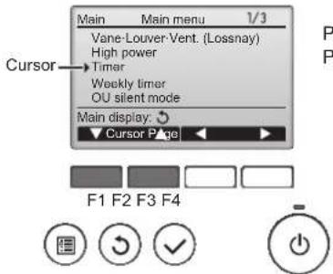
text_image
Main Vane-Louver Vent. (Lossnay) High power Timer Weekly timer OU silent mode Cursor Main display: ▼ Cursor Page F1 F2 F3 F4
text_image
Main Main menu 1/3 Vane-Louver-Vent. (Lossnay) High power Timer Weekly timer ▶ OU silent mode Main display: ▶ Cursor Page ▶ F1 F2 F3 F4
text_image
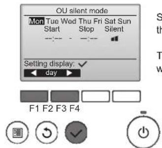
OU silent mode Mon Tue Wed Thu Fri Sat Sun Start Stop Silent Setting display: ✓ day F1 F2 F3 F4
text_image
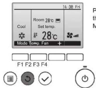
14:30 Fri Cool Room 28°C Set temp. 28°C Mode Temp. Fan + F1 F2 F3 F4If no buttons are touched for 10 minutes, the screen will automatically return to the Main display. Any settings that have not been saved will be lost.
text_image
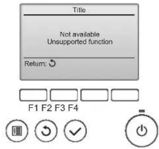
Title Not available Unsupported function Return: F1 F2 F3 F4The message at left will appear if the user selects a function not supported by the corresponding indoor unit model.
3.5.2. Vane-Vent. (Lossnay)
text_image
Main Main menu 1/3 ► Vane Louver Vent. (Lossnay) High power Timer Weekly timer OU silent mode Main display: ○ ▼ Cursor Page ▶ F1 F2 F3 F4Select "Vane·Louver·Vent. (Lossnay)" from the Main menu, and press the [SELECT] button.
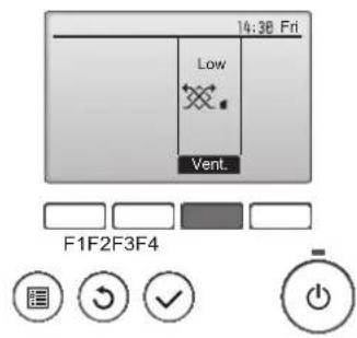
text_image
14:30 Fri Low Vent. F1F2F3F4Press the [F3] button to go through the ventilation setting options in the order of "Off", "Low", and "High".
* Settable only when LOSSNAY unit is connected.
- The fan on some models of indoor units may be interlocked with certain models of ventilation units.
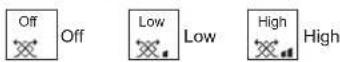
text_image
Main Main menu 1/3 ► Vane-Louver-Vent. (Lossnay) High power Timer Weekly timer OU silent mode Main display: ▼ Cursor Page ▶ ▶ F1 F2 F3 F4Press the [RETURN] button to go back to the Main menu.
3.6. Ventilation (For wireless remote controller)
● The ventilator will automatically operate when the indoor unit turns on.
● No indication on the wireless remote controller.
4. Timer
■ Timer functions are different by each remote controller.
■ For details on how to operate the remote controller, refer to the appropriate operation manual included with each remote controller.
4.1. For wireless remote controller (option)
text_image
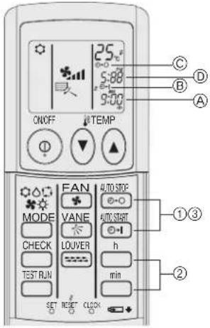
ON/OFF TEMP MODE FAN VANE CHECK LOUVER TEST RUN AUTO STOP AUTO START h min SET RESET CLOCK ①③ ② C D B A1) Set the current time
① Press the CLOCK button using a thin stick and blink the time Ⓐ.
② Press the ☐ and ☐ button to set the current time.
③ Press the CLOCK button using a thin stick.
2) Set the time to start the unit as follows
① Press the button.
- Time can be set while the following symbol is blinking.
On time: Ⓑ START is blinking.
• The start times is displayed at Ⓐ.
② Use the □ and □ buttons to set the desired time.
③ To cancel the ON timer, press the button.
3) Set the time to stop the unit as follows
① Press the button.
- Time can be set while the following symbol is blinking.
Off time: ©STOP is blinking.
• The stop times is displayed at Ⓓ.
② Use the □ and □ buttons to set the desired time.
③ To cancel the OFF timer, press the button.
4) Changing the set times
Press the ANDF1 or ANDF2 to cancel the timer and repeat from 2) or 3).
5. Emergency Operation for Wireless Remote-controller (option)
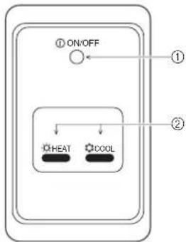
text_image
① ON/OFF ① HEAT COOL ②① ON/OFF lamp (lit when unit is operating; unlit when unit is not operating)
② Emergency operation
In cases where the remote control unit does not operate properly, use either the COOL or HEAT button on the wireless remote control signal receiver to toggle the unit on or off. On cooler only units, pushing the HEAT button toggles the fan on and off.
Pressing the COOL or HEAT button selects the following settings.
| Operation mode COOL | HEAT | |
| Preset temperature 24 | °C/75 °F 24 °C/75 °F | |
| Fan speed High High |
6. Trouble Shooting
| Having trouble? Here is the solution. (Unit is operating normally.) | |
| Air conditioner does not heat or cool well. | ■ Clean the filter. (Airflow is reduced when the filter is dirty or clogged.)■ Check the temperature adjustment and adjust the set temperature.■ Make sure that there is plenty of space around the outdoor unit. Is the Indoor unit air intake or outlet blocked?■ Has a door or window been left open? |
| When heating operation starts, warm air does not blow from the indoor unit soon. | ■ Warm air does not blow until the indoor unit has sufficiently warmed up. |
| During heating mode, the air conditioner stops before the set room temperature is reached. | ■ When the outdoor temperature is low and the humidity is high, frost may form on the outdoor unit. If this occurs, the outdoor unit performs a defrosting operation. Normal operation should begin after approximately 10 minutes. |
| A flowing water sound or occasional hissing sound is heard. | ■ These sounds can be heard when refrigerant is flowing in the air conditioner or when the refrigerant flow is changing. |
| A cracking or creaking sound is heard. | ■ These sounds can be heard when parts rub against each due to expansion and contraction from temperature changes. |
| The room has an unpleasant odor. | ■ The indoor unit draws in air that contains gases produced from the walls, carpeting, and furniture as well as odors trapped in clothing, and then blows this air back into the room. |
| A white mist or vapor is emitted from the indoor unit. | ■ If the indoor temperature and the humidity are high, this condition may occur when operation starts.■ During defrosting mode, cool airflow may blow down and appear like a mist. |
| Water or vapor is emitted from the outdoor unit. | ■ During cooling mode, water may form and drip from the cool pipes and joints.■ During heating mode, water may form and drip from the heat exchanger.■ During defrosting mode, water on the heat exchanger evaporates and water vapor may be emitted. |
| “” appears in the remote controller display. | ■ During central control, “” appears in the remote controller display and air conditioner operation cannot be started or stopped using the remote controller. |
| When restarting the air conditioner soon after stopping it, it does not operate even though the ON/OFF button is pressed. | ■ Wait approximately three minutes.(Operation has stopped to protect the air conditioner.) |
| Air conditioner operates without the ON/OFF button being pressed. | ■ Is the on timer set?Press the ON/OFF button to stop operation.■ Is the air conditioner connected to a central remote controller?Consult the concerned people who control the air conditioner.■ Does “” appear in the remote controller display?Consult the concerned people who control the air conditioner.■ Has the auto recovery feature from power failures been set?Press the ON/OFF button to stop operation. |
| Air conditioner stops without the ON/OFF button being pressed. | ■ Is the off timer set?Press the ON/OFF button to restart operation.■ Is the air conditioner connected to a central remote controller?Consult the concerned people who control the air conditioner.■ Does “” appear in the remote controller display?Consult the concerned people who control the air conditioner. |
| Remote controller timer operation cannot be set. | ■ Are timer settings invalid?If the timer can be set, “” appears in the remote controller display. |
| “PLEASE WAIT” appears in the remote controller display. | ■ The initial settings are being performed. Wait approximately 3 minutes. |
| An error code appears in the remote controller display. | ■ The protection devices have operated to protect the air conditioner.■ Do not attempt to repair this equipment by yourself.Turn off the power switch immediately and consult your dealer. Be sure to provide the dealer with the model name and information that appeared in the remote controller display. |
| Draining water or motor rotation sound is heard. | ■ When cooling operation stops, the drain pump operates and then stops. Wait approximately 3 minutes. |
| The fan speed changes in spite of not changing the setting. | ■ Not to blow out cold air at the beginning of heating operation, the air conditioner automatically adjusts the fan speed gradually from lower to the set speed. It also adjust its fan speed to protect the fan motor when return air temperature or fan speed excessively rises. |
6. Trouble Shooting
| Having trouble? Here is the solution. (Unit is operating normally.) | |||
| Noise is louder than specifications. | ■ The indoor operation sound level is affected by the acoustics of the particular room as shown in the following table and will be higher than the noise specification, which was measured in an echo-free room. | ||
| High sound-absorbing rooms | Normal rooms | ||
| Location examples | Broadcasting studio, music room, etc. | Reception room, hotel lobby, etc. | |
| Noise levels | 3 to 7 dB 6 to | 10 dB 9 to 13 dB | |
| Nothing appears in the wireless remote controller display, the display is faint, or signals are not received by the indoor unit unless the remote controller is close. | ■ The batteries are low.Replace the batteries and press the Reset button.■ If nothing appears even after the batteries are replaced, make sure that the batteries are installed in the correct directions (+,-). | ||
| The operation lamp near the receiver for the wireless remote controller on the indoor unit is flashing. | ■ The self diagnosis function has operated to protect the air conditioner.■ Do not attempt to repair this equipment by yourself.Turn off the power switch immediately and consult your dealer. Be sure to provide the dealer with the model name. | ||
7. Specifications
| Item | Model | PEA-M100GAA PEA | |||
| Dimension Height / Width / Depth mm 400/1400/634 400/1400/634 400/1400/634 | |||||
| Net weight kg 63 63 63 | |||||
| Fan | Airflow rate 50Pa m (Low-High) | ^3/min 34-42 | 48-60 | ||
| 100Pa | m^3/min 34-42 | 43-54 | |||
| 150Pa | m^3/min 34-42 | 41-52 | |||
| External static pressure | Pa | 50/100/150 | |||
| Sound pressure level (Low-High) | 50Pa dB(A) 39-42 | 42-45 | |||
| 100Pa | dB(A) 42-45 | 43-47 | |||
| 150Pa | dB(A) 44-48 | 45-49 | |||
-M125GAA PEA-M14
Please be sure to put the contact address/telephone number on this manual before handing it to the customer.