ADCI825LT-F311 - Security Camera Illustra - Free user manual and instructions
Find the device manual for free ADCI825LT-F311 Illustra in PDF.


| Product Type | Indoor Fisheye Security Camera |
| Model | ADCI825LT-F311 (Illustra Pro LT 5MP) |
| Resolution | 5 Megapixels (1936x1936 max) |
| Lens | Fisheye (180°+ field of view) |
| Mounting | Ceiling or Wall (software selectable) |
| Power | PoE IEEE 802.3af/at, 12.95W max |
| Dimensions (Vandal) | Body diameter 5.85" (149mm), height above ceiling 1.0" (25.4mm), below ceiling 2.91" (74mm) |
| Weight (Vandal) | 0.750 kg |
| Operating Temperature | 14°F to 113°F (-10°C to 45°C) |
| Storage Temperature | -4°F to 149°F (-20°C to 65°C) |
| Video Compression | H.264, MJPEG |
| Max Frame Rate | 14 fps at 5MP (primary stream); 14 fps at 736x736 (secondary) |
| Streams | Dual stream (primary and secondary fisheye) |
| Network Protocols | IPv4/IPv6, DHCP, DDNS, NTP, SMTP, FTP, ONVIF |
| Security | HTTPS, IEEE 802.1x, firewall, user access levels (admin/operator/user) |
| Storage | microSD card slot (max 32GB) for edge recording |
| Privacy Zones | Up to 4 rectangular zones, auto-move with PTZ |
| Motion Detection | Configurable sensitivity and actions (FTP, email, SD, or fault) |
| PTZ Control | Virtual PTZ (pan/tilt/zoom) via web interface or ONVIF |
| Vandal Resistance | IK10 impact rating |
| Regulatory Compliance | FCC Part 15 Class A, CE, UL 60950-1, RoHS |
| Included Software | Illustra Connect discovery tool (Windows) |
| Maintenance | Web-based firmware upgrade, backup/restore, reboot/reset via button |
| Warranty | Contact dealer; typical warranty period (not specified) |
Frequently Asked Questions - ADCI825LT-F311 Illustra
User questions about ADCI825LT-F311 Illustra
0 question about this device. Answer the ones you know or ask your own.
Ask a new question about this device
Download the instructions for your Security Camera in PDF format for free! Find your manual ADCI825LT-F311 - Illustra and take your electronic device back in hand. On this page are published all the documents necessary for the use of your device. ADCI825LT-F311 by Illustra.
USER MANUAL ADCI825LT-F311 Illustra
illustra
From Tyco Security Products
Configuration and User
Guide
Illustra Pro 5MP & Pro LT 5MP
Fisheye Cameras
Notice
The information in this manual was current when published. The manufacturer reserves the right to revise and improve its products. All specifications are therefore subject to change without notice.
Copyright
Under copyright laws, the contents of this manual may not be copied, photocopied, reproduced, translated or reduced to any electronic medium or machine-readable form, in whole or in part, without prior written consent of Tyco Security Products.
© 2018 Tyco Security Products. All rights reserved.
Tyco Security Products
6600 Congress Avenue
Boca Raton, FL 33487 U.S.A.
Customer Service
Thank you for using Illustra products. We support our products through an extensive worldwide network of dealers. The dealer through whom you originally purchased this product is your point of contact if you need service or support. Our dealers are empowered to provide the very best in customer service and support. Dealers should contact Tyco Security Products at (800) 507-6268 or (561) 912-6259 or on the Web at www.illustracameras.com.
Trademarks
Windows ® is a registered trademark of Microsoft Corporation. PS/2 is a registered trademark of International Business Machines Corporation.
The trademarks, logos, and service marks displayed on this document are registered in the United States [or other countries]. Any misuse of the trademarks is strictly prohibited and Tyco Security Products will aggressively enforce its intellectual property rights to the fullest extent of the law, including pursuit of criminal prosecution wherever necessary. All trademarks not owned by Tyco Security Products are the property of their respective owners, and are used with permission or allowed under applicable laws.
Product offerings and specifications are subject to change without notice. Actual products may vary from photos. Not all products include all features. Availability varies by region; contact your sales representative.
License Information
Your use of this product is governed by certain terms and conditions. Please see the detailed license information at the end of this manual.
Table of Contents
INTRODUCTION .... 1
OVERVIEW....1
INSTALLATION 2
CAMERAMOUNTS 2
BROWSERSUPPORT 2
NETWORKSETTINGS 2
ILLUSTRACONNECT .... 3
INSTALL AND DETECT THE ILLUSTRA PRO 5MP FISHEYE CAMERA....3
INSTALLATION USING DHCP AND ILLUSTRACONNECT....3
INSTALLING THE ILLUSTRA PRO 5MP FISHEYE CAMERA USING DHCP SERVER LOGS .... 4
WEBCONFIGURATION 6
ACCESSING THE ILLUSTRAPRO 5MP FISHEYE CAMERA WEB USER INTERFACE....6
THE CAMERA WEB USER INTERFACE....9
OVERVIEW OF THE WEB USER INTERFACE 11
WEB USER INTERFACE ICONS....12
VIDEOpane 13
CONTROLLING THE PRO 5MP FISHEYECAMERA USING PAN TILT ZOOM (PTZ)....14
BASIC CONFIGURATION MENU....17
-
CAMERA....18
-
USERS....19
-
DATETIME 21
-
TCP/IP 22
-
STREAMS 24
VIDEO MENU 29
PRO 5MP FISHEYE STREAMS....30
PRO LT 5MP FISHEYE STREAMS 34
CAMERA....39
PRIVACYZONES 41
PICTURESETTINGS....43
PICTUREBALANCE....44
ON-SCREENDISPLAY(OSD) 49
PTZ MENU....51
PRESETS 52
SEQUENCES....55
PATTERNS....58
SCANS....60
EVENTS MENU 63
FAULT SETTINGS 64
FTP 65
FAULTACTIONS....67
MOTIONDETECTION 69
SCHEDULED TASKS 73
APPLICATIONS....76
SECURITY....78
SECURITY STATUS 78
USERS....81
HTTP/HTTPS 83
IEEE 802.1x 84
FIREWALL 85
REMOTE ACCESS 87
ONVIF 88
NETWORK MENU....90
DATE TIME 91
TCP/IP 92
SMTP 94
FTP 96
DYNAMICDNS 97
MAINTENANCEMENU....99
BACKUP/RESTORE....100
CAMERAUPGRADE 101
REBOOT 102
RESET 103
SUPPORT MENU....105
CURRENTFAULTS....106
CURRENT EVENTS....108
LOGS 109
ENVIRONMENTAL....110
STATISTICS 111
EDGE RECORDING....112
SD CARD MANAGEMENT....112
ABOUT MENU 116
MODEL 116
TECHNICALSPECIFICATIONS....118
APPENDIX A: USER ACCOUNT ACCESS....128
APPENDIX B: USING VLC PLAYER TO VIEW RTSP....132
APPENDIX C: CAMERA DEFAULTS ....133
APPENDIX D: PHYSICAL REBOOT/RESET OF THE CAMERA....136
APPENDIX E: STREAM COMBINATIONS....138
Overview
The Illustra Pro 5MP and Pro LT 5MP Fisheye cameras, hereafter referred to as the camera, is a high definition fisheye camera utilizing the latest in IP technologies. ONVIF-compatibility allows interoperability with other ONVIF-compliant third party Network Video Recorders (NVRs), and the built-in web server allows you to configure the camera and stream video using a web browser.
The cameras can operate as a standalone camera on a network. However, it is intended to be integrated into sophisticated security solutions.
The cameras are available in the following configurations:
| Illustra Pro 5MP Fisheye Model Description | Product Codes |
| Illustra Pro 5MP Fisheye, indoor, white, vandal | ADCi825-F311 |
| Illustra Pro 5MP Fisheye, indoor, white, non-vandal | ADCi825-F312 |
| Illustra Pro LT 5MP Fisheye, indoor, white, vandal | ADCi825LT-F311 |
| Illustra Pro LT 5MP Fisheye, indoor, white, non-vandal | ADCi825LT-F312 |
Please refer to the Illustra web page to ensure that you have the most current version of this Configuration and User Guide. Release Notes that document any known limitations not covered in this user guide are also available at illustracameras.com for each software release.
This chapter provides detailed instructions on how to install the Illustra Pro 5MP Fisheye Camera. You can also refer to the printed Quick Installation Guide provided with the camera.
Camera mounts
Refer to the Attach the Mounting Bracket supplied with the camera for installation instructions.
Please refer to the Illustra website or contact your Illustra Sales Representative for more information on the various mounts and accessories that can be used with the Illustra Pro 5MP Fisheye camera.
Browser support
The Illustra Pro 5MP Fisheye camera supports the following operating systems and Internet browsers:
| Operating system | Browser |
| Microsoft Windows 7 | Chrome, Firefox, Safari, Internet Explorer (up to version 11) |
| Microsoft Windows XP | Chrome, Firefox, Safari, Internet Explorer (up to version 11) |
Network settings
The following provides the default network settings for the Illustra Pro 5MP Fisheye camera.
| Setting | Default |
| Camera Name | Illustra825fe-Serial number |
| DHCP | Enabled |
| IP Address | 192.168.1.168 |
| Subnet Mark | 255.255.255.0 |
| Default Gateway | 0.0.0.0 |
| DNS | 0.0.0.0 |
| HTTP Port | 80 |
Illustra Connect
Illustra Connect is an Illustra camera discovery tool and is supplied with the Illustra Pro 5MP Fisheye camera on the CD.
Connecting to IP cameras and configuring them can be a time-consuming and error-prone process. Typing static IP addresses, or naming cameras without seeing where they are pointed, often results in longer installations. Illustra Connect eliminates all of these issues with a unique feature set that includes a one-touch IP conflict resolver and snapshot tool. Simply bring up all of the cameras out of the box, enter the IP range provided by the customer's IT department and click OK.
Key functions of Illustra Connect are:
- Resolve All Conflicts button instantly alerts you to all IP addresses that are the same and provides a number of options to fix issues
- Greatly reduces installation time by automatically supplying static IP addresses from a configurable range of IP addresses
- Snapshot views of all of the cameras
- Save Device List allows you to create a .csv file of all information regarding the camera settings
- Set IP addresses using DHCP
- Configure IP settings and rename cameras
- Upload firmware to individual or a selectable group of cameras
- Set date and time or direct the cameras to a specific NTP server
- Assign user name and password
- Uses icons common to victor unified client to display camera status
- Compatible with Illustra IP cameras
Install and detect the Illustra Pro 5MP Fisheye camera
The following provides detailed information for installing and accessing the camera.
Installation using DHCP and Illustra Connect
The following provides information for installing the camera on your network using the Illustra Connect discovery tool.
Illustra Connect enables automatic discovery of compliant devices on IP networks and is the recommended method for installation and detection of the camera on the network.
Note
Illustra Connect only discovers devices on the same subnet as its host computer. Therefore the camera and the computer used to configure it must be on the same subnet.
Procedure 2-1 Installing the Illustra Pro 5MP Fisheye camera using Illustra Connect
Step Action
1 Using the Quick Start Guide instructions, install and connect the camera to the computer or network that is used for the configuration and power on.
The camera begins its initial boot up sequence which takes approximately 1 to 2 minutes.
2 When using a DHCP Server, the camera is automatically assigned a Network IP address.
3 Using a computer which is connected to the same network and subnet, install the Illustra Connect software that is provided with the camera. For more information, see the Illustra Connect User Guide.
4 When the installation is complete, run Illustra Connect. It searches the network and displays all compliant devices, including the Illustra Pro 5MP Fisheye Camera.
5 Select the camera you want to configure, locating it by its unique MAC address. Illustra Connect allows basic configuration of the camera.
For more information, see the Illustra Connect User Guide.
6 Right-click the camera and select Launch Web GUI Configuration.
7 Refer to the Web Configuration chapter for details on how to log in to the camera, view live video and modify the configuration.
- End -
Installing the Illustra Pro 5MP Fisheye Camera using DHCP Server Logs
Procedure 2-2 Installing the Illustra Pro 5MP Fisheye Camera using DHCP Server Logs
Step Action
1 Using the Quick Start Guide instructions, install and connect the camera to the computer or network that is used for the configuration and power on.
The camera begins its initial boot up sequence which takes approximately 1 to 2 minutes.
2 When using a DHCP Server, the camera is automatically assigned a Network IP Address.
3 View the DHCP Server system logs and make note of the IP address assigned to the camera.
4 Open Microsoft Internet Explorer and enter the URL of the camera as shown in the DHCP Server log.
Note
The computer you use to configure the camera must have an IP address on the same subnet.
5 Refer to the Web Configuration chapter for details on how to log in to the camera and modify the configuration.
- End -
Installation without a DHCP Server using a Static IP Address
The following provides information for installing the camera on your network when no DHCP Server is available. In this situation the camera is assigned a Static IP Address.
Note
1 We recommend that once you are logged into the Web Configuration pages you change the Static IP Address of the camera so that conflicts can be avoided when using the same Static IP Address to setup additional cameras.
2 In a situation where IP address conflicts arise, Illustra Connect can be used to discover the device. Refer to IP Address Conflicts in the Illustra Connect User Guide for further information.
Procedure 2-3 Installing the Illustra Pro 5MP Fisheye camera when a DHCP Server is not available
Step Action
1 Using the Quick Start Guide instructions, install and connect the camera to the computer or network that you are using for the configuration and power on. The camera will begin its initial boot up sequence which will take approximately 1 to 2 minutes.
2 The camera will attempt to obtain an IP Address from the DHCP Server. When no DHCP Server is available the camera will be assigned a Static IP address of 192.168.1.168.
3 Open Microsoft Internet Explorer and enter the URL of the camera as 192.168.1.168.
Note
1 The computer being used to configure the camera must have an IP address on the same subnet.
2 Illustra Connect can also be used to discover the camera when using a Static IP Address. For more information, see Procedure 2-1 Installing the Illustra Pro 5MP Fisheye camera using Illustra Connect and step 3.
4 Refer to the Web Configuration chapter for details on how to log in to the camera and modify the configuration.
- End -
This section details how to configure the camera using the built-in Web Configuration feature. Depending on user access and camera type you can view Live video and control the camera through Virtual PTZ (vPTZ) controls as well as changing the settings for the camera environment.
Note
1 Adobe Reader must be installed to view the online help.
2 Web Configuration sessions timeout after a period of inactivity.
3 Only users with administrative rights can access all the areas of the Web Configuration pages.
Security Mode profiles for first time connection
The Illustra Pro 5MP Fisheye Fixed Dome camera now has Enhanced Security features that allow for operation in a Standard Security mode or in an Enhanced Security mode.
The Enhanced Security mode of operation is used to control changes to the camera communication protocols HTTP, HTTPS, FTP, and SMTP. When the camera is in Enhanced Security mode, a complex Protocols seven character Administrator password is required to make changes to these protocols.
Accessing the Illustra Pro 5MP Fisheye Camera Web User Interface
Logging in to the camera
Use the following procedure to access the camera Web User Interface.
Procedure 3-1 Log in to the camera
Step Action
1 Refer to the installation procedures 2-1, 2-2, and 2-3 for details on how to connect the camera to your network or computer.
2 When the camera is selected the sign in page displays
3 Select your preferred language from the drop-down menu. The default language is 'English'.
4 Enter the username in the Username text box.
5 Enter the password in the Password text box.
Note
Security Profile: The first time you access the camera, you are prompted to use either the Standard Security or Enhanced Security. If you are keeping Standard Security, best practice is to use the Change Password check box to immediately change the default password to one unique to your surveillance system.
6 If you select the Enhanced Security option, you will be required and instructed to create a complex password.
Note:
The password must meet the following requirements:
- Be a minimum of seven characters long.
- Have at least one character from at least three of the following character groups:
• Upper-case letters - Lower-case letters
- Numeric characters
- Special characters
7 Select Log in.
The Live view page displays.
Depending on the access rights of the user account, there can be specific camera functions that are unavailable. All camera functions are described in this manual.
Note
The default Username is admin and the default Password is admin. To maintain security, change the password on the admin account. Refer to Procedure 9-5 Change User Password
Logging out of the camera
Use the following procedure to log off the camera Web User Interface.
Procedure 3-2 Log off the camera
- Select Log Off in the upper right hand corner of the Web User Interface. You are logged off the camera and the sign in page displays.
- End -
Changing the Camera Web User Interface language
Use the following procedure to change the language used in the camera Web User Interface.
Procedure 3-3 Change the camera Web User Interface language
Step Action
1 Open the camera sign in page. If you are already logged in to the User Interface, select Log Off to display the sign in page.
2 Select your preferred language from the drop-down menu:
- English
- Arabic
• Czech
- Danish
- German
- Spanish
- French
- Hungarian
- Italian
- Japanese
- Korean
• Dutch - Polish
- Portuguese
- Swedish
- Turkish
- Chinese Simplified
- Chinese Traditional
The default language is 'English'.
3 Enter the username in the Username text box.
4 Enter the password in the Password text box.
5 Select Log in.
The camera Web User Interface displays in the selected language.
- End -
User accounts
There are three types of user account that can be used to access the camera:
- Administrator
- Operator
- User
Refer to Appendix A: User Account Access for a breakdown of features which can be accessed by each user.
To add a new user refer to Procedure 9-4 Add a User.
Administrator access
The administrator account provides full access to the camera. This user account has access to all of the cameras functions and information.
Operator access
The operator account provides the following access:
- Video: Full access to Picture Settings. Video Streams can be edited. Mounting options and camera name can be modified. Privacy Zones can be created, edited and activated.
- PTZ (when supported): Full access to Presets, Sequences, Patterns and scans. However, patterns cannot be deleted.
• Events: Full access to all Event settings.
• Network: Operator account password can be changed. Access to Advanced Settings. - Support: Current Faults, Current Events, Environmental and Statistics can be viewed.
- About: Model information can be viewed.
User access
The user account provides the following access:
- PTZ (when supported): Presets, Sequences, Patterns and scans can be viewed and activated.
• Network: User account password can be changed. - About: Model information can be viewed.
The Camera Web User Interface
When logged into the camera the screen displays the live video feed full screen as seen in Figure 3-1 Live View Page.
Refer to Web User Interface Icons Web User Interface Icons on for information on the icons used throughout the Web User Interface.
Figure 3-1 Live View Page

Accessing the Setup Menus from Live View
Setup menus within the Web User Interface are restricted by user account access levels.
For more information, see Appendix A: User Account Access for details on the features which are available to each role.
Procedure 3-4 Access Setup Menus from Live View
When displaying full screen live video select Setup on the Web User Interface banner to access the setup menus. The Model page displays.
Note
When an admin user logs in for the first time the Basic Configuration page will be displayed. After this, on each login the Model page displays.
Displaying the Live View Page
Display the live camera view page.
Procedure 3-5 Display Live View Page
| Step | Action |
| 1 | SelectLivein the GUI banner.The live view page displays. Refer toConfiguring the web video streamto edit display settings. |
| 2 | Select a video stream fromStreamto view:12345The default setting is ‘Stream 1’.Note |
| Streams 1 to 5 are applicable to the Pro 5MP Fisheye camera. Streams 1 to 2 are applicable to the Pro LT 5MP Fisheye camera. | |
| Note | |
| Depending on the stream configuration, stream 3, and 4 are no longer available since 1.3 FW. Refer toStreamsfor further information. | |
| 3 | Select a percentage fromScaleto change the display size of the video pane:25%50%75%100%The default setting is ‘25%’. |
- End -
Overview of the Web User Interface
Figure 3-2 The Camera Web User Interface provides an overview of the Illustra Pro 5MP Fisheye Camera Web User Interface.
Figure 3-2 Camera Web User Interface

Web User Interface Icons
The following provides information on the icons used throughout the camera interface. These icons will be referenced throughout this manual:
 | Select to start streaming video to the video pane. |  | Select to stop streaming video to the video pane. |
 | Check box, deselected. |  | Check box, selected. |
 | Delete the corresponding function. |  | Refresh the current tab. |
 | View or activate the corresponding function. | [T=88] | Edit the corresponding function. |
 | Hide the active tab details. |  | Unhide the active tab details |
 | Slider bar - The slider bar can be moved left or right using the mouse. For fine adjustments, select the slider bar with the mouse and use the left and right arrow keys on the PC keyboard to adjust the slider. | ||
| [48K4] | Select the page number or arrows to navigate through the corresponding pages. | ||
Video Pane
The video pane provides a simple way to view the live video stream from the camera when using the Web User Interface. The live viewing page however is not intended to be the primary way of viewing the video on the camera; this should be performed using the Network Video Recording device.
Viewing live streams through the Video Pane
The video pane is accessible to any authorized user and is displayed when accessing the Web User Interface menus. It is not displayed on the following pages; Current Faults, Current Events, Logs and Scheduled Tasks.
Procedure 3-6 Viewing live video through the Video Pane
Step Action
1 The video stream starts automatically when a page is opened.
Refer to Configuring the web video stream to edit display settings.
2 Select □ to stop the video stream.
3 If the video has been stopped, select ▶ to start the video stream.
- End -
Maximize the Video Pane on an Active Tab
The maximize and minimize icon allows you to switch between a normal active tab layout and one where the video pane has been maximized.
Procedure 3-7 Maximize or minimize the Video Pane
Step Action
1 Select a tab to display from the menu.
The selected tab displays.
2 Select to maximize the video pane.
3 Select to minimize the video pane.
Controlling the Pro 5MP Fisheye camera using Pan Tilt Zoom (PTZ)
This section is not applicable to the Pro LT 5MP Fisheye camera. The new line camera can be controlled using the on-screen controls in the video pane. Virtual PTZ (hereafter referred to as vPTZ) camera controls are available for smooth and accurate motion control.
vPTZ camera controls
The following provides information on the controls that are available for the on-screen camera control.
Note
The camera control overlay is only visible when viewing an Active Image; either Active Image 1, or Active Image 2.
Figure 3-5 Camera control overlay

Note
It is possible for two users to access live viewing at the same time. However, only one user can control the camera at any time. Camera control operates on a “last come, first served” basis, therefore when a new user logs into the camera from a different browser and starts a camera control session, the original user loses their camera control session.
Controlling the camera through camera controls
The camera can be controlled using the on-screen controls displayed on the Active Image in the video pane.
Note
The camera control overlay is only visible when viewing an Active Image; either Active Image 1, or Active Image 2.
Procedure 3-8 Controlling the camera through the Video Pane
Step Action
1 Select ▶ to start the video stream if it is not already active. The video pane displays the current camera view.
2 Select an Active Image as the video stream.
3 Select the camera control item on the overlay to activate the vPTZ control. Refer to Figure 3-5 Camera Control Overlay for further information.
- End -
Controlling the Camera using keyboard shortcuts
The following keyboard shortcuts can be used to control the camera using vPTZ.
Figure 3-6 Keyboard Shortcuts

Controlling the camera using keyboard shortcuts
The camera can be controlled using vPTZ using specific keys on the keyboard.
Note
Keyboard controls can only be used when viewing an Active Image; either Active Image 1, or Active Image 2.
Procedure 3-9 Controlling the camera using the keyboard shortcuts
Step Action
1 Select ▶ to start the video stream if it is not already active.
The video pane displays the current camera view.
2 Select an Active Image as the video stream.
3 Select the appropriate key on the keyboard to camera to activate the vPTZ control.
Refer to Figure 3-6 Keyboard Shortcuts for further information.
- End -
Basic Configuration Menu
When the Basic Configuration menu is selected Figure 4-1 Basic Configuration Menu displays.
Note
When an admin user logs in for the first time the Basic Configuration page displays. After this, on each login the Model page displays.
Figure 4-1 Basic Configuration Menu

The Basic Configuration menu provides access to the most common features required when setting up a camera for the first time and is only available to an 'admin' user.
Basic Configuration includes the following settings and functions:
• 1. Camera
• 2. Users
• 3. Date Time
• 4. TCP/IP
- 5. Streams
1. Camera
This section provides access to the camera mounting options and allows you to add a camera name.
Refer to Streams for additional information.
Mounting
Procedure 4-1 Set Mounting Position for the camera
| Step | Action |
| 1 | Select Setup on the GUI banner to display the setup menus. |
| 2 | Select 1. Camera from the Basic Configuration menu.The Mounting tab displays. |
| 3 | Select the required Mounting by selecting the radio buttons:• Wall• CeilingThe default setting is ‘Ceiling’.You are prompted to confirm the update. |
| 4 | Select OK to save the change and reboot the camera. When the camera is restarted it will take 2 - 3 minutes until it is online and ready to be accessed and controlled.Refer to Procedure 3-1 Log in to the Camera to log back into the camera Web User InterfaceOrSelect Cancel. |
| Note |
The Pro LT 5MP model does not require a reboot after the Mounting selection is changed.
- End -
Camera Name
The camera name displayed on the Web User Interface banner and the on-screen display for the camera. This name will also be displayed when using Illustra Connect or ONVIF.
Procedure 4-2 Edit the Camera Name
| Step | Action |
| 1 | Select Setup on the Web User Interface banner to display the setup menus. |
| 2 | Select 1. Camera from the Basic Configuration menu. |
| 3 | Select the Camera Name tab. |
The Camera Name tab displays.
4 Enter the name of the camera in the Camera Friendly Name text box.
5 Select Apply to save the changes.
- End -
2. Users
In this section you are able to add a user, change a user password and a delete user account.
There are three levels of access: admin, operator and user.
Refer to Appendix A: User Account Access for details on the features which are available to each role.
Note
The default Username is admin and the default Password is admin. To maintain security the password on the admin account should be changed.
Add User
Add a new user account to allow access to the camera.
Procedure 4-3 Add a User
Step Action
1 Select Setup on the Web User Interface banner to display the setup menus.
2 Select 2. Users from the Basic Configuration menu.
3 Select the Add User tab.
The Add User tab
displays.
4 Enter a User Name in the Name text box.
The username must start with a letter and can be followed by any alphanumeric values (a-z, A-Z, 0-9) and the following special characters, underscore(_, dash(-), or dot(.)
5 Select a Role:
- admin
- operator
- user
Refer to Appendix A: User Account Access for details on the features which are available to each role.
6 Enter a password in the Password text box.
The password must start with an alphanumeric character and is case sensitive; it can contain alphanumeric characters with a length of between 4 and 32 characters.
7 Enter the same password in the Confirm Password text box.
8 Select Apply to save the settings.
The new user account are displayed in the Users list on the Users tab.
- End -
Changing the User accounts password
Change the password of an existing user account.
Procedure 4-4 Change user password
| Step | Action |
| 1 | Select Setup on the GUI banner to display the setup menus. |
| 2 | Select 2.Users from the Basic Configuration menu.The 2. Users tab displays. |
| 3 | Select the Change Password tab.The Change Password tab displays. |
| 4 | Select the user account from the Name drop-down menu. |
| 5 | Enter the current password for the user account in the Current Password text box. |
| 6 | Enter the new password for the user account in the New Password text box.The password is case sensitive and can contain alphanumeric characters with a length of between 4 and 32 characters. |
| 7 | Enter the same new password in the Confirm New Password text box. |
| 8 | Select Apply to save the settings. |
- End -
View current user accounts
View a list of the current user accounts assigned to the camera.
Procedure 4-5 View user accounts
Step Action
1 Select Setup on the GUI banner to display the setup menus.
2 Select 2. Users from the Basic Configuration menu.
The Users tab displays.
3 The current user accounts assigned to the camera will be displayed.
- End -
Delete a user account
Delete a user account from the camera.
Note
The default 'admin' account cannot be deleted.
Procedure 4-6 Delete a user account
Step Action
1 Select Setup on the GUI banner to display the setup menus.
2 Select 2. Users from the Basic Configuration menu.
The Users tab displays.
3 Select ☐ to delete the corresponding user account.
You are prompted to confirm the deletion.
4 Select OK to delete.
Or
Select Cancel.
- End -
3. Date Time
Set the date and time for the camera manually or using NTP.
Setting Date Time
Set the date and time on the camera.
Procedure 4-7 Configuring the date and time
Step Action
1 Select Setup on the GUI banner to display the setup menus.
2 Select 3. Date Time from the Basic Configuration menu.
The Date Time tab displays.
3 Select the Time 24-hour check box to enable the 24-hour clock.
Or
Deselect the Time 24-hour check box to enable the 12-hour clock.
The default setting is '24-hour'.
4 Select the Date Display Format from the drop-down menu:
- DD/MM/YYYY
- MM/DD/YYYY
- YYYY/MM/DD
The default setting is 'YYYY/MM/DD'.
5 Select the Time Zone from the drop-down menu.
The default setting is ‘(GMT-05:00) Eastern Time (US & Canada)
6 Select the Set Time setting by selecting the radio buttons:
- Manually
- via NTP
The default setting is 'Manually'.
7 If you select Manually in step 5:
a Select the Date (DD/MM/YYYY) using the drop-down menus.
b Select the Time (HH:MM:SS) using the drop-down menus.
8 If you select via NTP in step 5:
a Enter the NTP Server Name in the text box.
9 Select Apply to save the settings.
- End -
4. TCP/IP
Configure the IPv4 and IPv6 network settings on the camera.
IPv4
Configure the IPv4 network settings for the camera.
Procedure 4-8 Configure the IPv4 Settings
| Step | Action |
| 1 | Select Setup on the Web User Interface banner to display the setup menus. |
| 2 | Select 4. TCP/IP from the Basic Configuration menu.The IPv4 tab displays. |
| 3 | Select the Enable DHCP check box to enable DHCP and disable manual settings.OrDeselect Enable DHCP to disable DHCP and allow manual settings to be entered.The default setting is ‘Enabled’. |
| 4 | If Enable DHCP has been disabled:a Enter the IPv4 Address in the IPv4 Address text box in the form xxx.xxx.xxx.xxx.The default setting is ‘192.168.1.168’b Enter the Network Mask in the Network Mask text box xxx.xxx.xxx.xxx.The default setting is ‘255.255.255.0’c Enter the Gateway IP address in Gateway text box xxx.xxx.xxx.xxx.d Enter the Primary DNS Server in the Primary DNS Server text box xxx.xxx.xxx.xxx.e Enter the Secondary DNS Server in the Secondary DNS Server text boxxxx.xxx.xxx.xxx. |
| 5 | Select Apply to save the settings. |
- End -
DHCP
On initial camera startup, and after a hardware factory reset, Dynamic Host Configuration Protocol (DHCP) is enabled by default and remains enabled until the camera receives either a DHCP address or is assigned a Static IP address.
Procedure 4-9 Enable DHCP
| Step | Action |
| 1 | Select Setup on the Web User Interface banner to display the setup menus. |
| 2 | Select 4. TCP/IP from the Basic Configuration menu.The IPv4 tab displays. |
| 3 | Select the Enable DHCP check box to enable DHCP and disable manual settings. |
| 4 | Select Apply to save the settings.The camera will search for a DHCP server. If one is found, it will connect to the server. If no connection is made to a DHCP server within two minutes, the camera goes to the default IP address 192.168.1168, but continues to search for a DHCP address. If the camera is assigned a Static IP address prior to DHCP being enabled, the camera first reboots for approximately 30 seconds and then remains accessible at its Static IP until a connection is made to a DHCP server. |
- End -
Procedure 4-10 Disable DHCP
| Step | Action |
| 1 | Select Setup on the Web User Interface banner to display the setup menus. |
| 2 | Select 4. TCP/IP from the Basic Configuration menu.The IPv4 tab displays. |
| 3 | Clear the Enable DHCP check box to disable DHCP and allow manual settings to be entered.The default setting is ‘Enabled’ |
| 4 | If Enable DHCP has been disabled:a) Enter the IPv4 Address in the IPv4 Address text box in the form xxx.xxx.xxx.xxx.b) Enter the Network Mask in the Network Mask text box xxx.xxx.xxx.xxx.The default setting is ‘255.255.255.0’c) Enter the Gateway IP address in Gateway text box xxx.xxx.xxx.xxx.d) Enter the Primary DNS Server in the Primary DNS Server text box xxx.xxx.xxx.xxx. |
| 5 | Select Apply to save the settings. |
- End -
IPv6
Enable or disable IPv6 on the camera.
Procedure 4-11 Enable/Disable IPv6
| Step | Action |
| 1 | Select Setup on the Web User Interface banner to display the setup menus. |
| 2 | Select 4. TCP/IP from the Basic Configuration menu. |
| 3 | Select the IPv6 tab. |
| The IPv6 tab displays. | |
| 4 | Select the IPv6 Enable check box to enable IPv6 on the camera. |
| Or | |
| Deselect the IPv6 Enable check box to disable IPv6 on the camera. | |
| The default setting is ‘enabled’. | |
| If IPv6 is enabled the Link Local and DHCP address will be displayed beside ‘Current IPv6 Addresses’ if available. | |
| - End - | |
5. Streams
The camera allows the configuration of five independent video streams. These streams can be configured using the Web User Interface, as detailed here or using the Illustra API or Network Video Recorder.
Configuring the web video stream
Adjust the settings for video displayed on the video pane.
Procedure 4-12 Configure the video stream settings
| Step | Action |
| 1 | Select Setup on the Web User Interface banner to display the setup menus. |
| 2 | Select 5. Streams from the Basic Configuration menu.The Stream 1 tab displays. |
| 3 | Select either the Stream 1, Stream 2, Stream 3, Stream 4, or Stream 5 tab to configure the settings.NoteStream 3, 4 and 5 are not applicable to the Pro LT 5MP Fisheye camera. |
| 4 | Select the required Image Source from the drop-down menu: |
- Fisheye
• Wall/Ceiling Panorama (panorama option depends on mounting selection)
• Active Image 1
• Active Image 2
• Active Image 3
• Active Image 4
- Quad Image
Note:
Wall/Ceiling Panorama, Active Image 1, Active Image 2, Active Image 3, Active Image 4 and Quad are not applicable to the Pro LT 5MP Fisheye camera.
5 Select the required Codec by selecting the radio buttons:
• H264
- MJPEG
The default setting is 'H264'.
6 Select the required Resolution from the drop-down menu. The resolutions available depend on the Image Source selected:
Pro LT 5MP Fisheye Stream.
| Pro LT 5MP Fisheye Stream Table | ||||
| Primary Stream | Secondary Stream | |||
| Resolution | Max Frame Rate | Codec | Resolution | Codec |
| 1936x1936 | 14 | H.264/MJPEG | 736x736 | MJPEG |
| 640x640 | MJPEG | |||
| 480x480 | MJPEG | |||
| 320x320 | MJPEG | |||
| 176x176 | MJPEG | |||
Note: The Primary and secondary streams are locked to the same frame rate.
Wall Mode.
In this mode, the camera can stream a wall panorama or 4 PTZ active images or quad image (4 x PTZ active images in the same stream).
| Wall Mode | ||||
| Wall Panorama | ||||
| Primary Stream | Secondary Stream | |||
| Resolution | Max Frame Rate | Codec | Resolution | Codec |
| 1920x1080 | 15 | H.264/MJPEG | 960x540 | MJPEG |
| 1600x900 | 15 | H.264/MJPEG | 800x450 | MJPEG |
| 1280x720 | 15 | H.264/MJPEG | 640x360 | MJPEG |
| 1024x576 | 15 | H.264/MJPEG | 480x270 | MJPEG |
| 960x540 | 15 | H.264/MJPEG | 320x180 | MJPEG |
| 800x450 | 15 | H.264/MJPEG | ||
| 640x260 | 15 | H.264/MJPEG | ||
| 480x270 | 15 | H.264/MJPEG | ||
| 320x180 | 15 | H.264/MJPEG | ||
| Wall Mode | ||||
| Active Image (1-4) | ||||
| Primary Stream | Secondary Stream | |||
| Resolution | Max Frame Rate | Codec | Resolution | Codec |
| 960x540 | 12 | H.264/MJPEG | 960x540 | MJPEG |
| 800x450 | 12 | H.264/MJPEG | 800x450 | MJPEG |
| 640x360 | 12 | H.264/MJPEG | 640x360 | MJPEG |
| 480x270 | 12 | H.264/MJPEG | 480x270 | MJPEG |
| 320x180 | 12 | H.264/MJPEG | 320x180 | MJPEG |
| Wall Mode | ||||
| Quad Image | ||||
| Primary Stream | Secondary Stream | |||
| Resolution | Max Frame Rate | Codec | Resolution | Codec |
| 960x540 | 12 | H.264/MJPEG | 960x540 | MJPEG |
| 800x450 | 12 | H.264/MJPEG | 800x450 | MJPEG |
| 640x360 | 12 | H.264/MJPEG | 640x360 | MJPEG |
| 480x270 | 12 | H.264/MJPEG | 480x270 | MJPEG |
| 320x180 | 12 | H.264/MJPEG | 320x180 | MJPEG |
- Primary Stream and Secondary Stream are locked to the same frame rate.
- Active Image Primary Stream and Active Image Secondary Stream are locked to the same resolution.
Ceiling Mode.
Basic Configuration Menu
In this mode, the camera can stream a ceiling panorama or 4 PTZ active images or quad image (4 x PTZ active images in the same stream).
| Ceiling Mode | ||||
| Ceiling Panorama | ||||
| Primary Stream | Secondary Stream | |||
| Resolution | Max Frame Rate | Codec | Resolution | Codec |
| 1920x1080 | 15 | H.264/MJPEG | 960x540 | MJPEG |
| 1600x900 | 15 | H.264/MJPEG | 800x450 | MJPEG |
| 1280x720 | 15 | H.264/MJPEG | 640x360 | MJPEG |
| 1024x576 | 15 | H.264/MJPEG | 480x270 | MJPEG |
| 960x540 | 15 | H.264/MJPEG | 320x180 | MJPEG |
| 800x450 | 15 | H.264/MJPEG | ||
| 640x360 | 15 | H.264/MJPEG | ||
| 480x270 | 15 | H.264/MJPEG | ||
| 320x180 | 15 | H.264/MJPEG | ||
| Ceiling Mode | ||||
| Active Image (1-4) | ||||
| Primary Stream | Secondary Stream | |||
| Resolution | Max Frame Rate | Codec | Resolution | Codec |
| 960x540 | 12 | H.264/MJPEG | 960x540 | MJPEG |
| 800x450 | 12 | H.264/MJPEG | 800x450 | MJPEG |
| 640x360 | 12 | H.264/MJPEG | 640x360 | MJPEG |
| 480x270 | 12 | H.264/MJPEG | 480x270 | MJPEG |
| 320x180 | 12 | H.264/MJPEG | 320x180 | MJPEG |
| Ceiling Mode | ||||
| Quad Image | ||||
| Primary Stream | Secondary Stream | |||
| Resolution | Max Frame Rate | Codec | Resolution | Codec |
| 960x540 | 12 | H.264/MJPEG | 960x540 | MJPEG |
| 800x450 | 12 | H.264/MJPEG | 800x450 | MJPEG |
| 640x360 | 12 | H.264/MJPEG | 640x360 | MJPEG |
| 480x270 | 12 | H.264/MJPEG | 480x270 | MJPEG |
| 320x180 | 12 | H.264/MJPEG | 320x180 | MJPEG |
- Primary Stream and Secondary Stream are locked to the same frame rate.
- Active Image Primary Stream and Active Image Secondary Stream are locked to the same resolution.
LT Model Streams.
The LT model camera has no Edge Dewarp capability. Two Fisheye streams are supported as shown in the table below:
| Stream 1 | Stream 2 | ||||
| Resolution | Max Frame Rate | Codec | Resolution | Max Frame Rate | Codec |
| 1936x1936 | 14 | H.264/MJPEG | 736x736 | 14 | H.264/MJPEG |
| 640x640 | |||||
| 480x480 | |||||
| 320x320 | |||||
| 176x176 | |||||
Use the slider bar to select the Frame Rate (ips). The default settings are:
- Fisheye - 14 ips
• Wall/Ceiling Panorama - 15 ips
• Active Images - 12 ips - Quad View - 12 ips
7 If MJPEG has been selected, MJPEG Quality is enabled. Use the slider bar to select the MJPEG Quality.
The default setting is 50.
OR
8 If H264 has been selected in step 4, Rate Control will be enabled. Select the required Rate Control by selecting the radio buttons:
• VBR (Variable Bit Rate)
• CBR (Constant Bit Rate)
The default setting is 'VBR'.
a If VBR has been selected, VBR Quality is enabled. Select the required VBR Quality from the drop-down menu.
- Highest
- High
- Medium
- Low
- Lowest The default setting is 'Highest'.
OR
a If CBR has been selected, CBR Bit Rate will be enabled. Use the slider bar to select the CBR Bit Rate.
The default setting is 1000.
- End -
When the view menu is selected Figure 5-1 Video Menu will be displayed
Figure 5-1 Video Menu

The Video Menu provides access to the following camera settings and functions:
- Streams
- Camera
- Privacy Zones
- Picture Settings
- On-Screen Display (OSD)
Pro 5MP Fisheye Streams
The camera allows the configuration of up to five independent video streams, Stream 1, Stream 2, Stream 3, Stream 4 and Stream 5. These streams can be configured through the Web User Interface, as detailed here or through the Illustra API.
Defining video streams
Video displayed on the video pane use the settings configured in the selected stream, either Stream 1, Stream 2, Stream 3, Stream 4 or Stream 5.
Stream Combinations.
| Stream 1 | Stream 2 | Stream 3 | Stream 4 | Stream 5 |
| Dual Stream | Dual Stream | Dual Stream | Dual Stream | Dual Stream |
| Fisheye | Fisheye | Not Available | Not Available | Not Available |
| Fisheye | Ceiling Panorama | Not Available | Not Available | Not Available |
| Fisheye | Wall Panorama | Not Available | Not Available | Not Available |
| Fisheye | Active Image X | Active Image X | Active Image X | Active Image X |
| Fisheye | Quad Image | Not Available | Not Available | Not Available |
| Ceiling Panorama | Fisheye | Not Available | Not Available | Not Available |
| Ceiling Panorama | Ceiling Panorama | Not Available | Not Available | Not Available |
| Wall Panorama | Fisheye | Not Available | Not Available | Not Available |
| Wall Panorama | Wall Panorama | Not Available | Not Available | Not Available |
| Active Image X | Fisheye | Active Image X | Active Image X | Active Image X |
| Active Image X | Active Image X | Active Image X | Active Image X | Active Image X |
| Quad Image | Quad Image | Not Available | Not Available | Not Available |
Image source
The image source for each video stream can be configured depending on the type of view required from the camera. There are five types of image source, the selections can be made from Fisheye, Ceiling or Wall Panorama and Active Image 1, 2, 3 and 4.
Fisheye
This provides the entire field of view from the camera.

i825Fisheye-ALPHA2_4 Help admin LOG OFF
Pro

□
Wall Panorama
This provides a 180 degree view from the camera.

Ceiling Panorama
This provides two 180 degree views which cover the field of view from the camera.

Active Image 1, 2, 3 and 4
This provides a selected view within the cameras field of view which utilizes Virtual PTZ controls.

Quad View
This provides 4 different fields of view at once.

Pro LT 5MP Fisheye Streams
The camera allows the configuration of a dual streaming Fisheye image which can be configured independently through Stream 1 and Stream 2. These streams can be configured through the Web User Interface, as detailed here or through the Illustra API.
Image source
The image source is a Fisheye, no other image sources are available
Alarm video
When setting up motion detection on the camera any of the pre-configured video streams can be used for the recording of alarm video. Refer to Fault Actions for more information on selecting a video stream for a motion detection alarm.
Integration with American Dynamics Network Video Recorders
The video stream image sources will have to be configured using the camera Web User Interface prior to adding the camera to the Network Video Recorder interface. Depending on the image sources selected the camera will add as two or up to five individual streams.
If changes are made to the image source (selecting Fisheye, Ceiling/Wall Panorama and Active Stream) while the camera is configured on the Network Video Recorder the change will not be updated on the recorder and it may be necessary to remove the camera and add it again to pick up the image source change.
Integration with other Illustra API Clients
The five video streams can be configured using the Web User Interface, as detailed here or using the Illustra API interface. Changes made to the streams using either method are applied and the video is displayed according to the configuration. Opening the Web User Interface live video allows the stream to be shared with the Illustra API and minimizes the impact on camera resources.
Configuring the video stream
Adjust the settings for the video streams.
Procedure 5-1 Configure the video stream settings
| Step | Action |
| 1 | Select Setup on the Web User Interface banner to display the setup menus. |
| 2 | Select Streams from the Video menu.The Stream 1 tab displays. |
| 3 | Select either the Stream 1, Stream 2, Stream 3, Stream 4 or Stream 5 tab to configure the settings. |
| 4 | Select the required Image Source from the drop-down menu:FisheyeWall/Ceiling Panorama (panorama option depends on mounting selection) Fisheye Active Image 1Active Image 2Active Image 3Active Image 4Quad ImageNote:Wall/Ceiling Panorama, Active Image 1, Active Image 2, Active Image 3, Active Image 4 and Quad are not applicable to the Pro LT 5MP Fisheye cameraThe default setting for Stream 1 is ‘Fisheye’ and Stream 2 is ‘Ceiling Panorama’.Refer to Streams for further information.NoteIf motion detection has been enabled and the image source is modified motion detection will be disabled and you will have to be re-enable. Refer to Procedure Enable or Disable a Motion Detection Alert, for more information. |
5 Select the required Codec by selecting the radio buttons:
• H264
- MJPEG
The default setting is 'H264'.
6 Select the required Resolution from the drop-down menu. The resolutions available will depend on the Image Source selected:
Pro LT 5MP Fisheye Stream.
| Pro LT 5MP Fisheye Stream Table | ||||
| Primary Stream | Secondary Stream | |||
| Resolution | Max Frame Rate | Codec | Resolution | Codec |
| 1936x1936 | 14 | H.264/MJPEG | 736x736 | MJPEG |
| 640x640 | MJPEG | |||
| 480x480 | MJPEG | |||
| 320x320 | MJPEG | |||
| 176x176 | MJPEG | |||
Note: The Primary and secondary streams are locked to the same frame rate.
Wall Mode.
In this mode, the camera can stream a wall panorama or 4 PTZ active images or quad image (4 x PTZ active images in the same stream).
| Wall Mode | ||||
| Wall Panorama | ||||
| Primary Stream | Secondary Stream | |||
| Resolution | Max Frame Rate | Codec | Resolution | Codec |
| 1920x1080 | 15 | H.264/MJPEG | 960x540 | MJPEG |
| 1600x900 | 15 | H.264/MJPEG | 800x450 | MJPEG |
| 1280x720 | 15 | H.264/MJPEG | 640x360 | MJPEG |
| 1024x576 | 15 | H.264/MJPEG | 480x270 | MJPEG |
| 960x540 | 15 | H.264/MJPEG | 320x180 | MJPEG |
| 800x450 | 15 | H.264/MJPEG | ||
| 640x260 | 15 | H.264/MJPEG | ||
| 480x270 | 15 | H.264/MJPEG | ||
| 320x180 | 15 | H.264/MJPEG | ||
| Wall Mode | ||||
| Active Image (1-4) | ||||
| Primary Stream | Secondary Stream | |||
| Resolution | Max Frame Rate | Codec | Resolution | Codec |
| 960x540 | 12 | H.264/MJPEG | 960x540 | MJPEG |
| 800x450 | 12 | H.264/MJPEG | 800x450 | MJPEG |
| 640x360 | 12 | H.264/MJPEG | 640x360 | MJPEG |
| 480x270 | 12 | H.264/MJPEG | 480x270 | MJPEG |
| 320x180 | 12 | H.264/MJPEG | 320x180 | MJPEG |
| Wall Mode | ||||
| Quad Image | ||||
| Primary Stream | Secondary Stream | |||
| Resolution | Max Frame Rate | Codec | Resolution | Codec |
| 960x540 | 12 | H.264/MJPEG | 960x540 | MJPEG |
| 800x450 | 12 | H.264/MJPEG | 800x450 | MJPEG |
| 640x360 | 12 | H.264/MJPEG | 640x360 | MJPEG |
| 480x270 | 12 | H.264/MJPEG | 480x270 | MJPEG |
| 320x180 | 12 | H.264/MJPEG | 320x180 | MJPEG |
- Primary Stream and Secondary Stream are locked to the same frame rate.
- Active Image Primary Stream and Active Image Secondary Stream are locked to the same resolution.
Ceiling Mode.
In this mode, the camera can stream a ceiling panorama or 4 PTZ active images or quad image (4 x PTZ active images in the same stream).
| Ceiling Mode | ||||
| Ceiling Panorama | ||||
| Primary Stream | Secondary Stream | |||
| Resolution | Max Frame Rate | Codec | Resolution | Codec |
| 1920x1080 | 15 | H.264/MJPEG | 960x540 | MJPEG |
| 1600x900 | 15 | H.264/MJPEG | 800x450 | MJPEG |
| 1280x720 | 15 | H.264/MJPEG | 640x360 | MJPEG |
| 1024x576 | 15 | H.264/MJPEG | 480x270 | MJPEG |
| 960x540 | 15 | H.264/MJPEG | 320x180 | MJPEG |
| 800x450 | 15 | H.264/MJPEG | ||
| 640x360 | 15 | H.264/MJPEG | ||
| 480x270 | 15 | H.264/MJPEG | ||
| 320x180 | 15 | H.264/MJPEG | ||
| Ceiling Mode | ||||
| Active Image (1-4) | ||||
| Primary Stream | Secondary Stream | |||
| Resolution | Max Frame Rate | Codec | Resolution | Codec |
| 960x540 | 12 | H.264/MJPEG | 960x540 | MJPEG |
| 800x450 | 12 | H.264/MJPEG | 800x450 | MJPEG |
| 640x360 | 12 | H.264/MJPEG | 640x360 | MJPEG |
| 480x270 | 12 | H.264/MJPEG | 480x270 | MJPEG |
| 320x180 | 12 | H.264/MJPEG | 320x180 | MJPEG |
| Ceiling Mode | ||||
| Quad Image | ||||
| Primary Stream | Secondary Stream | |||
| Resolution | Max Frame Rate | Codec | Resolution | Codec |
| 960x540 | 12 | H.264/MJPEG | 960x540 | MJPEG |
| 800x450 | 12 | H.264/MJPEG | 800x450 | MJPEG |
| 640x360 | 12 | H.264/MJPEG | 640x360 | MJPEG |
| 480x270 | 12 | H.264/MJPEG | 480x270 | MJPEG |
| 320x180 | 12 | H.264/MJPEG | 320x180 | MJPEG |
- Primary Stream and Secondary Stream are locked to the same frame rate.
- Active Image Primary Stream and Active Image Secondary Stream are locked to the same resolution.
LT Model Streams.
The LT model camera has no Edge Dewarp capability. Two Fisheye streams are supported as shown in the table below:
| Stream 1 | Stream 2 | ||||
| Resolution | Max Frame Rate | Codec | Resolution | Max Frame Rate | Codec |
| 1936x1936 | 14 | H.264/MJPEG | 736x736 | 14 | H.264/MJPEG |
| 640x640 | |||||
| 480x480 | |||||
| 320x320 | |||||
| 176x176 | |||||
7 Use the slider bar to select the Frame Rate (ips). The default setting are.
- Fisheye - 14 ips
• Wall/Ceiling Panorama - 15 ips
• Active Images - 12 ips - Quad View - 12 ips
8 If MJPEG has been selected, MJPEG Quality is enabled. Use the slider bar to select the MJPEG Quality.
The default setting is 50.
OR
9 If H264 has been selected in step 4, Rate Control is enabled. Select the required Rate Control by selecting the radio buttons:
• VBR (Variable Bit Rate)
• CBR (Constant Bit Rate)
The default setting is 'VBR'.
a If VBR has been selected, VBR Quality is enabled. Select the required VBR Quality from the drop-down menu.
- Highest
• High - Medium
- Low
- Lowest
The default setting is 'High'.
OR
a If CBR has been selected, CBR Bit Rate will be enabled. Use the slider bar to select the CBR Bit Rate. The default setting is 1000.
- End -
Camera
This section provides access to the camera mounting options and allows you to designate a camera name.
Mounting Position of camera
Select the mounting position for the camera, this will depend on whether the camera has been wall mounted or ceiling mounted
Figure 5-2 Mounting Options

Wall
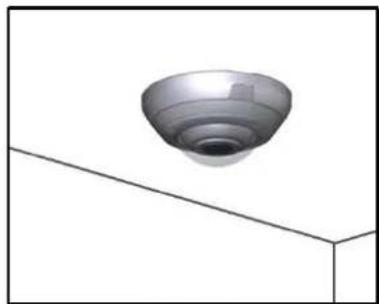
Ceiling
Procedure 5-2 Set Mounting Position for the camera
Step Action
1 Select Setup on the Web User Interface banner to display the setup menus.
2 Select Camera from the Video menu.
The Mounting tab displays.
3 Select the required Mounting by selecting the radio buttons:
- Wall
- Ceiling
The default setting is 'Ceiling'.
You will be prompted to confirm the update.
4 Select OK to save the change and reboot the camera. When the camera is restarted it will take 2 - 3 minutes until it is online and ready to be accessed and controlled.
Refer to Procedure 3-1 Log in to the Camera to access the camera Web User Interface.
Or
Select Cancel.
Note
The Pro LT 5MP model does not require a reboot after the Mounting selection is changed.
- End -
Camera Name
The camera name is displayed on the Web User Interface banner and the on-screen display for the camera.
Note
Refer to Procedure 5-15 Display or Hide the Camera Name for information on how to display the camera name on the OSD.
Procedure 5-3 Edit the camera name
Step Action
1 Select Setup on the GUI banner to display the setup menus.
2 Select Camera from the Video menu.
3 Select the Camera Name tab.
The Camera Name tab displays.
4 Enter the name of the camera in the Camera Friendly Name text box.
The default setting is 'i825Fisheye-serial number'.
5 Select Apply to save the changes.
- End -
Privacy Zones
Note
A privacy zone can only be created when using a Fisheye image source. Refer to Procedure 5-1 Configure the Video Stream settings to change settings for the video stream.
Privacy Zones are “masked” sections of the camera’s viewing area. These masks prevent operators of the surveillance system who do not have access to the camera password from viewing these designated zones. Each zone has four sides, and the zones may overlap to form irregular shapes. The Privacy Zones move in relation to the camera pan/tilt position.
In addition, the apparent size of the Privacy Zone adjusts automatically as the zoom level is adjusted. Privacy Zones are useful for high security areas. For example, you might establish a privacy Zone around a safe's combination, but still view people approaching or opening the safe.
Up to 4 rectangular privacy zones can be used on the camera.
Note
Areas of the Privacy Zone may be exposed during rapid pan / tilt movements of the camera. To compensate for this limitation, you may want to program the Privacy Zone to be 20 to 25% larger than the area you want to mask.
Defining a Privacy Zone
Create a privacy zone on the camera.
Note
A privacy zone can only be created when using a Fisheye image source. Refer to Procedure 5-1 Configure the Video Stream settings to change settings for the video stream.
Procedure 5-4 Define a privacy zone
Step Action
1 Select Setup on the GUI banner to display the setup menus.
2 Select Privacy Zones from the Video menu.
3 Select the Add Zone tab.
The Add Zone tab displays.
4 Select 📋 to start the video stream if it is not already active. The video pane will display the current camera view.
5 Enter the privacy zone name in the Privacy Zone Name text box.
6 Select Draw.
The image will freeze and a still image will be displayed. The Add page updates to display an Add and Cancel button.
7 Using the cursor locate the start point for the privacy zone, click and drag on the still image to define the privacy zone area. As the cursor is moved a red shape will appear on the image which highlights the privacy zone.
8 Release the mouse button.
The selected privacy area will turn red.
9 To reselect an alternative area for the privacy zone repeat steps 7 and 8.
10 Select Add to save the current privacy zone.
Or
Select Cancel.
Note
When a new privacy zone is created it is automatically enabled, refer to
Procedure 5-5 Enable/Disable a Privacy Zone to modify this setting.
- End -
Enabling or Disabling a privacy zone
Select a privacy zone to hide or display on the camera.
Procedure 5-5 Enable/Disable a Privacy Zone
Step Action
1 Select Setup on the GUI banner to display the setup menus.
2 Select Privacy Zones from the Video
menu. The Privacy Zones tab displays.
3 Select ▶ to start the video stream if it is not already
active. The video pane will display the current camera
view.
4 Select the corresponding Enabled check box to enable the privacy
zone. Or
Deselect the corresponding Enabled check box to disable the privacy zone.
5 Select ▶ to view the corresponding privacy zone.
Note
When an Active Image 1, 2, is displayed the video pane will update to display the activated privacy zone centered on the video pane.
- End -
Deleting a privacy zone
Delete a privacy zone from the camera.
Procedure 5-6 Delete a privacy zone
Step Action
1 Select Setup on the Web User Interface banner to display the setup menus.
2 Select Privacy Zones from the Video
menu. The Privacy zones tab displays.
3 Select the corresponding Delete check box to mark the privacy zone for deletion.
Note
More than one privacy zone can be deleted at a time. The Select All check box can also be used.
4 Select Delete to delete the selected privacy
zones. You are prompted to confirm the deletion.
5 Select OK to confirm the
deletion. Or
Select Cancel.
- End -
Picture settings
Adjust settings for White Balance, Picture Balance, WDR and save and restore Picture settings.
White Balance
White balance (the ability to keep whites looking white) is normally compensated for automatically using the default Auto White Balance (AWB) setting.
Manual White Balance (MWB) is available when specific color temperature settings want to be set and preserved. This can be done using the red and blue slider adjustments set for optimal viewing.
Configuring White Balance
Adjust the white balance.
Procedure 5-7 Configure Auto White Balance
Step Action
1 Select Setup on the Web User Interface banner to display the setup menus.
2 Select Picture Settings from the Video menu. The White Balance tab displays.
3 Select ▶ to start the video stream if it is not already active.
4 The video pane displays the current camera view.
5 Select the required White Balance from the drop-down menu:
- Auto Normal
- Auto Wide
- Manual
The default setting is 'Auto Normal'.
If Manual is selected refer to Procedure 5-8 Manually Select White Balance on page 56.
- End -
Manually select White Balance
Adjust the white balance manually.
Procedure 5-8 Manually select White Balance
Step Action
1 Select Setup on the Web User Interface banner to display the setup menus.
2 Select Picture Settings from the Video
menu. The White Balance tab displays.
3 Select ▶ to start the video stream if it is not already
active. The video pane displays the current camera view.
4 Select Manual from the White Balance drop-down menu. The Red and Blue slider bars will be displayed.
5 Use the slider bars to adjust the Red and Blue balance. The live video pane will update to display the new settings.
The red and blue values range from 1% to 100%.
The default settings are Red 30% and Blue 30%.
- End -
Picture Balance
Adjust brightness, contrast and saturation of the image displayed in the video pane.
Adjusting Picture Balance
Configure brightness, contrast and saturation.
Procedure 5-9 Adjust the Brightness, Contrast and Saturation
Step Action
1 Select Setup on the Web User Interface banner to display the setup menus.
2 Select Picture Settings from the Video menu.
3 Select the Picture Balance tab.
The Picture Balance tab displays.
4 Select ▶ to start the video stream if it is not already
active. The video pane will display the current camera view.
5 Use the slider bars to adjust:
- Brightness
- Contrast
- Saturation (color level)
The video pane updates to display the new settings. The values range from 0% to 100%.
The default values are 50%.
- End -
Restoring Picture Balance defaults
Use this procedure to restore picture balance settings to factory default settings.
Procedure 5-10 Restore Picture Balance defaults
Step Action
1 Select Setup on the Web User Interface banner to display the setup menus.
2 Select Picture Settings from the Video menu.
3 Select the Picture Balance tab.
The Picture Balance tab displays.
4 Select Defaults to restore the default settings.
The default settings are 50%.
- End -
Wide Dynamic Range
Configuring WDR
Wide Dynamic Range (WDR) is a feature that allows viewing of high contrast scenes that include both bright and low light areas in the same field of view (FOV).
WDR Level allows you to adjust the WDR level to favour an underexposed or overexposed image. By selecting the lower end of the control the image is underexposed which provides more detail in areas of bright but less details in areas of darkness. Selecting the higher end of the control the image is overexposed which provides more detail in the dark areas but less detail in the bright areas.
A typical use for this feature would be viewing a scene with both indoor and outdoor lighting
conditions simultaneously, for example, in a warehouse area with an open bay door.
Procedure 5-11 Disable/Enable Wide Dynamic Range (WDR)
Step Action
1 Select Setup on the Web User Interface banner to display the setup menus.
2 Select Picture Settings from the Video menu.
3 Select the WDR tab.
The WDR tab displays.
4 Select the WDR check box to enable WDR.
Or
Deselect the WDR check box to disable WDR.
The default setting is 'Disabled'.
5 Use the slider bar to adjust the WDR Level.
The video pane will update to display the new settings.
The values range from 0% to 100%.
The default value is 50%.
- End -
Procedure 5-12 Configure Exposure Settings
Step Action
1 Select Setup on the Web User Interface banner to display the setup menus.
2 Select Picture Settings from the Video menu.
3 Select the Flicker Control tab.
4 Select the Frequency radio button for either 50Hz or 60 Hz.
The default setting is 60Hz.
5 Select or clear the check for Flickerless Mode.
This feature is not selected by default.
- When you select Flickerless Mode, the minimum and maximum exposure times are locked to 1/100 and 1/50 respectively (PAL) or 1/120 and 1/60 respectively (NTSC). This applies to all cameras referenced in this guide.
- End -
Picture settings
The picture options allow you to save the current settings, restore saved settings or restore to factory default settings.
Saving picture settings
Save the current picture settings to the camera.
Note
If the camera is rebooted or powered off, upon restart the picture settings return to the last saved settings. If picture settings have not been saved, upon restart the camera uses the default picture settings.
Procedure 5-13 Save current picture settings
| Step | Action |
| 1 | Select Setup on the Web User Interface banner to display the setup menus. |
| 2 | Select Picture Settings from the Video menu. |
| 3 | Select the Picture Settings tab.The Picture Settings tab displays. |
| 4 | Select Save to save and retain the current picture settings. |
| - End - | |
Restoring saved picture settings
Restore previously saved picture settings.
Procedure 5-14 Restore saved picture settings
| Step | Action |
| 1 | Select Setup on the Web User Interface banner to display the setup menus. |
| 2 | Select Picture Settings from the Video menu. |
| 3 | Select the Picture Settings tab.The Picture Settings tab displays. |
| 4 | Select Restore to restore the previously saved picture settings. |
| Note | |
| Restore will only be enabled if picture settings have been previously saved. |
5 You will be prompted to confirm the overwrite of the current camera settings.
6 Select OK to confirm the overwrite.
OR
Select Cancel.
- End -
Restoring factory default picture settings
Restore the factory default picture settings.
Procedure 5-15 Restore factory picture settings
Step Action
1 Select Setup on the Web User Interface banner to display the setup menus.
2 Select Picture Settings from the Video menu.
3 Select the Picture Settings tab.
The Picture Settings tab displays.
4 Select Defaults to restore the factory picture settings.
5 You will be prompted to confirm the overwrite of the current camera settings with the factory defaults.
6 Select OK to confirm the overwrite.
OR
Select Cancel.
- End -
On-Screen Display (OSD)
Within OSD you can set the display options for camera name and time.
Displaying the camera name
The camera name will be shown on the on-screen display (OSD) if the option is enabled.
Procedure 5-16 Display or hide the camera name
Step Action
1 Select Setup on the Web User Interface banner to display the setup menus.
2 Select OSD from the Video menu.
The name tab displays.
3 Select the Camera Name check box to display the camera name in the OSD.
Or
Deselect the Camera Name check box to hide the camera name in the OSD.
- End -
Displaying the camera time
The camera time will be shown on the on-screen display (OSD) if the option is enabled.
Procedure 5-17 Display or hide the Camera Time
Step Action
1 Select Setup on the Web User Interface banner to display the setup menus.
2 Select OSD from the Video menu.
3 Select the Time tab.
The Time tab displays.
4 Select the Time check box to display the camera name in the OSD.
Or
Deselect the Time check box to hide the camera name in the OSD.
The default setting is 'Disabled'.
- End -
This section in only applicable to the Pro 5MP Fisheye camera. When the view menu is selected Figure 6-1 View Menu will be displayed.
Figure 6-1 View Menu

The PTZ Menu provides access to the following camera settings and functions:
- Presets
- Sequences
- Patterns
- Scans
Note
1 The selected stream must use an Active Image source (either Active Image 1, 2, 3 or 4) to complete functions in the PTZ section. Refer to Procedure 5-1 Configure the Video Stream settings to change settings for the video stream.
2 Patterns, Sequences and Scans can only be run on one Active Image source at a time. Other Active Image sources configured on the camera can utilize vPTZ if required.
3 Preset, Patterns and Sequences are unique to the Active Image source (either Active Image 1, 2, 3 or 4) on which they are defined.
Presets
A Preset is a pre-positioned camera scene that you program using the pan, tilt and zoom options. A Preset is unique to the Active Image source (either Active Image 1, 2, 3 or 4) on which it is defined. Up to 96 presets can be programmed for each active image source on the camera.
Adding a new Preset
Create a new preset position on the camera.
Note
1 The selected stream must use an Active Image source (either Active Image 1, 2, 3 or 4) to use the preset function. Refer to Procedure 5-1 Configure the Video Stream settings to change settings for the video stream.
2 A preset is unique to the Active Image source (either Active Image 1, 2, 3 or 4) on which it is defined. Up to 96 presets can be programmed for each Active Image source on the camera.
Procedure 6-1 Add a Preset
| Step | Action |
| 1 | Select Setup on the Web User Interface banner to display the setup menus. |
| 2 | Select Presets from the PTZ menu.The Preset tab displays. |
| 3 | Select [IMAGE] to start the video stream if it is not already active.The video pane will display the current camera view. |
| 4 | Adjust the camera view as required.• Pan, Tilt and Zoom.Refer to Procedure 3-8 Controlling the Camera via the Video Pane on page 15 to make the required adjustments. |
| 5 | The following camera controls can be modified and saved as part of the preset and accessed via the Picture Settings menu:• White Balance• Picture Balance• Wide Dynamic Range (WDR) |
| 6 | In a numbered slot on the preset table, select [IMAGE] to add the new preset. |
| 7 | Enter the preset name in the Preset Name text box. |
| 8 | Select Add to save the preset.OrSelect Cancel. |
- End -
Viewing a Preset
View an existing preset position.
Note
1 The selected stream must use an Active Image source (either Active Image 1, 2, 3 or 4) to use the preset function. Refer to Procedure 5-1 Configure the Video Stream settings on to change settings for the video stream.
2 A preset is unique to the Active Image source (either Active Image 1, 2, 3 or 4) on which it was defined.
Procedure 6-2 View a Preset
Step Action
1 Select Setup on the Web User Interface banner to display the setup menus.
2 Select Presets from the PTZ menu.
The Preset tab displays.
3 Select ▶ to start the video stream if it is not already active.
The video pane displays the current camera view.
4 Select ▶ to activate the corresponding preset.
The video pane updates to display the selected preset. The preset displays until interrupted by a camera command, pattern or scan.
- End -
Editing a Preset
Edit an existing preset position.
Note
1 The selected stream must use an Active Image source (either Active Image 1, 2, 3 or 4) to use the preset function. Refer to Procedure 5-1 Configure the Video Stream settings to change settings for the video stream.
2 A preset is unique to the Active Image source (either Active Image 1, 2, 3 or 4) on which it was defined.
Procedure 6-3 Edit an existing Preset
Step Action
1 Select Setup on the Web User Interface banner to display the setup menus.
2 Select Presets from the PTZ menu.
The Preset tab displays.
3 Select ▶ to start the video stream if it is not already active.
The video pane displays the current camera view.
4 Select ☐ to activate the corresponding preset.
The video pane update to display the selected preset.
5 Select to edit the corresponding preset.
6 Edit the preset name in the Preset Name text box if required.
7 Adjust the camera view as required.
- Pan, Tilt and Zoom.
Refer to Controlling the Camera via PTZ on page 19 to make the required adjustments.
8 The following camera controls can be saved as part of the preset and accessed via the Picture Settings menu:
- White Balance
- Picture Balance
- Wide Dynamic Range (WDR)
9 Select Add to save the updated preset.
You will be prompted to confirm the update.
10 Select OK to save the changes.
Or
Select Cancel.
- End -
Deleting a Preset
Delete an existing preset position from the camera.
Procedure 6-4 Delete a Preset
Step Action
1 Select Setup on the Web User Interface banner to display the setup menus.
2 Select Presets from the PTZ menu.
The Preset tab displays.
3 Select ☐ to delete the corresponding preset.
You are prompted to confirm the deletion.
Note
You cannot delete a preset while it is associated with another camera function. To remove the preset refer to the associated camera function.
4 Select OK to confirm the deletion.
- End -
Sequences
A Sequence is a sequential display of multiple camera Presets. Sequences provide a methodical and effective way to monitor multiple areas of interest by switching to different Presets automatically.
Sequences are created by identifying Preset views to include in the Sequence and specifying a dwell time that controls how long each Preset remains on-screen before switching to another Preset.
Up to 16 Sequences can be created.
Adding a sequence
Create a new sequence on the camera using defined presets. Refer to Procedure 6-1 Add a Preset if no presets have yet been added to the camera.
Note
1 The selected stream must use an Active Image source (either Active Image 1, 2, 3 or 4) to use the sequence function. Refer to Procedure 5-1 Configure the Video Stream settings, to change settings for the video stream.
2 Patterns, Sequences and Scans can only be run on one Active Image source at a time. Other Active Image sources configured on the camera can utilize vPTZ if required.
3 A Sequence is unique to the Active Image source (either Active Image 1, 2, 3 or 4) on which it is defined.
Procedure 6-5 Add a Sequence
Step Action
1 Select Setup on the Web User Interface banner to display the setup menus.
2 If no presets have been created refer to Procedure 6-1 Add a Preset before continuing to step 2.
3 Select Sequences from the PTZ menu.
4 Select the Add Sequence tab.
The Add Sequence tab displays.
5 Enter the sequence name in the Sequence Name text box.
6 Select a preset from the Preset Name drop-down menu.
7 Enter a dwell time in seconds in the Dwell Time (sec) text box.
8 Select Add. The preset is now listed as part of the sequence.
9 Repeat steps 5 to 7 to add further presets to the sequence.
Note
Up to 16 presets can be added to a sequence.
10 Select Apply to save the sequence.
- End -
Activating a sequence
Activate a selected sequence.
Note
1 The selected stream must use an Active Image source (either Active Image 1, 2, 3 or 4) to use the preset function. Refer to Procedure 5-1 Configure the Video Stream settings, to change settings for the video stream.
2 Patterns, Sequences and Scans can only be run on one Active Image source at a time. Other Active Image sources configured on the camera can utilize vPTZ if required.
3 A Sequence is unique to the Active Image source (either Active Image 1, 2, 3 or 4) on which it is defined.
Procedure 6-6 Activate a Sequence
Step Action
1 Select Setup on the Web User Interface banner to display the setup menus.
2 Select Sequences from the PTZ menu.
The Sequences tab displays.
3 Select ▶ to start the video stream if it is not already active.
The video pane displays the current camera view.
4 Select ▶ to activate the corresponding sequence.
The video pane updates to display the selected sequence. The sequence will run continuously until interrupted by a camera command, pattern, preset, scan or alarm.
- End -
Editing a Sequence
Edit an existing sequence.
Note
1 The selected stream must use an Active Image source (either Active Image 1, 2, 3 or 4) to use the preset function. Refer to Procedure 5-1 Configure the Video Stream settings, to change settings for the video stream.
2 Patterns, Sequences and Scans can only be run on one Active Image source at a time. Other Active Image sources configured on the camera can utilize vPTZ if required.
Procedure 6-7 Edit a sequence
Step Action
1 Select Setup on the Web User Interface banner to display the setup menus.
2 Select Sequences from the PTZ menu.
The Sequences tab displays.
3 Select □ to edit the corresponding sequence.
The sequence will open in the Edit Sequence tab.
4 Edit the sequence name in the Sequence Name text box if required.
5 Select ☐ to edit the corresponding preset, the following can be edited: Preset Name
To add a new preset to the sequence, move to the next available free slot and select a preset from the Preset Name drop-down menu.
- Dwell time
6 If required, select 📄 to remove the corresponding preset from the sequence.
7 Select Add to save the changes
Or
Select Cancel.
8 Select Apply to save the changes.
- End -
Deleting a Sequence
Delete an existing sequence.
Procedure 6-8 Delete a sequence
Step Action
1 Select Setup on the Web User Interface banner to display the setup menus.
2 Select Sequences from the PTZ menu.
The Sequences tab displays.
3 Select □ to delete the corresponding sequence.
You will be prompted to confirm the deletion.
4 Select OK to delete the sequence.
Or
Select Cancel.
- End -
Patterns
A pattern is a series of pan, tilt and zoom movements which can be saved to the camera. A maximum of 16 patterns can be programmed for the camera with an unlimited duration.
Adding a Pattern
Create a new pattern.
Note
1 A 15 minute time out period is implemented when adding a pattern. If no command is received within the time out period the Add a Pattern procedure will automatically terminate.
2 The selected stream must use an Active Image source (either Active Image 1, 2, 3 or 4) to use the patterns function. Refer to Procedure 5-1 Configure the Video Stream settings on page 5-40 to change settings for the video stream.
3 A Pattern is unique to the Active Image source (either Active Image 1, 2, 3 or 4) on which it is defined.
4 Patterns, Sequences and Scans can only be run on one Active Image source at a time. Other Active Image sources configured on the camera can utilize vPTZ if required.
Procedure 6-9 Add a Pattern
Step Action
1 Select Setup on the Web User Interface banner to display the setup menus.
2 Select Patterns from the PTZ menu.
3 Select the Record tab.
The Record tab displays.
4 Select ▶ to start the video stream if it is not already active.
The video pane will display the current camera view.
5 Enter the pattern name in the Pattern Name text box.
6 Select Start.
The Record page will update with an Add and Cancel button.
7 Adjust the camera view as required.
- Pan, Tilt and Zoom.
Refer to Controlling the Camera via PTZ on page 19 to make the required adjustments.
8 Select Add to save the pattern.
Or
Select Cancel.
- End -
Running a Pattern
Activate an existing pattern.
Note
1 The selected stream must use an Active Image source (either Active Image 1, 2, 3 or 4) to use the preset function. Refer to Procedure 5-1 Configure the Video Stream settings, to change settings for the video stream.
2 Patterns, Sequences and Scans can only be run on one Active Image source at a time. Other Active Image sources configured on the camera can utilize vPTZ if required.
Procedure 6-10 Run a Pattern
Step Action
1 Select Setup on the Web User Interface banner to display the setup menus.
2 Select Patterns from the PTZ menu.
The Patterns tab displays.
3 Select ▶ to start the video stream if it is not already active.
The video pane will display the current camera view.
4 Select ▶ to activate the corresponding pattern.
The video pane will update to display the selected pattern. The pattern will run continuously until interrupted by a camera command, pattern, scan or alarm.
- End -
Deleting a Pattern
Delete an existing pattern.
Procedure 6-11 Delete a Pattern
Step Action
1 Select Setup on the Web User Interface banner to display the setup menus.
2 Select Patterns from the PTZ menu.
The Patterns tab displays.
3 Select □ to delete the corresponding pattern.
You will be prompted to confirm the deletion.
Note
You cannot delete a pattern while it is associated with another camera function. To remove the pattern, refer to the associated camera function.
4 Select OK to confirm the deletion.
Or
- End -
Repeating a Pattern
Use this procedure to have a pattern repeat until interrupted by a camera command.
Procedure 6-12 Enable/Disable Repeat a Pattern
Step Action
1 Select Setup on the Web User Interface banner to display the setup menus.
2 Select Patterns from the PTZ menu.
3 Select the Repeat tab.
The Repeat tab displays.
4 Select the Repeat Pattern check box to allow the selected pattern to repeat continuously. Or
Deselect the Repeat Pattern check box to allow selected pattern to run only once.
The default setting is 'Enabled'.
- End -
Scans
A scan allows you to program left and right scan limits to automate surveillance activities. Once these scan limits are programmed you can choose to run a smooth scan, stepped scan, or random scan. When active, the scan repeats until interrupted by a camera command, preset, pattern or alarm.
Setting Scan Limits
Set left and right scan limits on the camera.
Note
1 The selected stream must use an Active Image source (either Active Image 1, 2, 3 or 4) to use the scans function. Refer to Procedure 5-1 Configure the Video Stream settings, to change settings for the video stream.
2 Patterns, Sequences and Scans can only be run on one Active Image source at a time. Other Active Image sources configured on the camera can utilize vPTZ if required.
Procedure 6-13 Set Scan Limits
Step Action
1 Select Setup on the Web User Interface banner to display the setup menus.
2 Select Scans from the PTZ menu.
3 Select the Scan Limits tab. The Scans Limits tab displays.
4 Select ▶ to start the video stream if it is not already active.
The video pane will display the current camera view.
5 Adjust the camera view as required to locate the left scan limit.
Refer to Controlling the Camera via PTZ on page 19 to make the necessary adjustments.
6 Select Set Left to set the displayed position as the left limit.
7 Adjust the camera view as required to locate the right scan limit.
8 Select Set Right to set the displayed position as the right limit.
The scan limits have been set and the selected scan will now run within the scan limits set.
- End -
Set Scan Limits to default settings
Return the camera to the default scan settings.
Note
1 The selected stream must use an Active Image source (either Active Image 1, 2, 3 or 4) to use the scans function. Refer to Procedure 5-1 Configure the Video Stream settings, to change settings for the video stream.
2 Patterns, Sequences and Scans can only be run on one Active Image source at a time. Other Active Image sources configured on the camera can utilize vPTZ if required.
Procedure 6-14 Set Scan Limits to default settings
Step Action
1 Select Setup on the Web User Interface banner to display the setup menus.
2 Select Scans from the PTZ menu.
3 Select the Scan Limits tab.
The Scans Limits tab displays.
4 Select Defaults.
The scan limits will default to Left: 0 and Right: 359.
- End -
Activating a scan
Activate a scan on the camera, this will run using the scan limits saved in Setting Scan Limits.
Note
1 The selected stream must use an Active Image source (either Active Image 1, 2, 3 or 4) to use the scans function. Refer to Procedure 5-1 Configure the Video Stream settings, to change settings for the video stream.
2 Patterns, Sequences and Scans can only be run on one Active Image source at a time. Other Active Image sources configured on the camera can utilize vPTZ if required.
Procedure 6-15 Activate a scan
| Step | Action |
| 1 | Select Setup on the Web User Interface banner to display the setup menus. |
| 2 | Refer to Procedure 6-13 Set Scan Limits on page 6-68 before activating a scan. |
| 3 | Select Scans from the PTZ menu.The Scans tab displays. |
| 4 | Select ▶ to start the video stream if it is not already active.The video pane will display the current camera view. |
| 5 | Select ▶ to activate the corresponding scan.smooth - slowly pans between the left and right scan limits, starting at the left scan limit. When the right scan limit is reached, the scan reversesstepped - pans slowly, pausing briefly every 10° between the left and right scan limits. Once the right scan limit is reached, the scan reverses.random - pans randomly between the left and right scan limits. For example, the scan may start at 10° , then pan right 40° and pause, pan right 20° and pause, pan left 30° and pause, and pan right until it reaches the right scan limit. |
| 6 | The video pane will update to display the selected scan.The scan will run continuously until interrupted by a camera command, pattern, preset or alarm. |
- End -
When the Event Menu is selected Figure 7-1 Events Menu will be displayed
Figure 7-1 Events Menu

The Event Menu provides access to the following camera settings and functions:
- Fault Settings
- Fault Actions
- Motion Detection
- Scheduled Tasks
Fault Settings
Configure the Record Settings, SMTP, FTP and CIFs details which are required when setting Fault Actions for Motion Detection alerts.
SMTP
Configure the SMTP FTP settings to allow e-mail alerts to be sent from the camera when a motion detection alert is triggered.
Configure SMTP
SMTP settings must be configured to enable email alerts when using motion alerts.
Note
SMTP settings can also be configured through the Network menu.
Procedure 7-2 Configure SMTP settings
Step Action
1 Select Setup on the Web User Interface banner to display the setup menus.
2 Select Fault Settings from the Events menu.
3 Select the SMTP tab.
The SMTP tab displays.
4 Enter the IP Address of the mail server in the Mail Server text box.
5 Enter the server port in the Server Port text box.
The default setting is '25'.
6 Enter the from email address in the From Address text box.
7 Enter the email address to send email alerts to in the Send Email to text box.
8 Select the Use authentication to log on to server check box to allow authentication details to be entered.
Or
Deselect the Use authentication to log on to server to disable authentication.
The default setting is 'Disabled'.
Note:
When in Enhanced Security mode, enabling SMTP requires the admin account password.
9 If 'Use authentication to log on to server' check box has been selected:
a Enter the username for the SMTP account in the Username text box.
b Enter the password for the SMTP account in the Password text box.
10 Select Apply to save the settings.
Note
Refer to Procedure 7-3 Test the SMTP Settings, to confirm that the SMTP settings are working as expected.
- End -
Test SMTP Settings
Test the SMTP settings that have been configured in Procedure 7-2 Configure SMTP Settings.
Procedure 7-3 Test the SMTP Settings
Step Action
1 Select Setup on the Web User Interface banner to display the setup menus.
2 Select Fault Settings from the Events menu.
3 Select the SMTP tab. The SMTP
tab displays.
If Procedure 7-2 Configure SMTP Settings have been configured a Test button will be displayed.
4 Select Test.
A test email will be sent to the specified email address to confirm that SMTP settings are correct. The camera will display a message confirming that the transfer was either successful or failed.
- End -
FTP
Configure the FTP settings for the FTP server. This is required to send video files from triggered motion detection alerts.
Configuring FTP Server Settings
FTP must be configured to enable FTP video alerts when using motion detection.
Note
FTP settings can also be configured through the Network menu.
Procedure 7-4 Configure FTP Server Settings
Step Action
1 Select Setup on the Web User Interface banner to display the setup menus.
2 Select Fault Settings from the Events menu.
3 Select the FTP tab.
The FTP tab displays.
4 Enter the IP address of the FTP Server in the FTP Server text box.
5 Enter the FTP port in the FTP Port text box.
The default setting is 21.
6 Select the Use authentication to log on to server check box to allow authentication details to be entered.
Or
Deselect the Use authentication to log on to server to disable authentication.
The default setting is 'Disabled'.
Note:
When in Enhanced Security mode, enabling FTP requires the admin account password.
7 If Use authentication to log on to server check box has been selected:
a Enter the FTP username in the Username text box.
b Enter the FTP password in the Password text box.
8 Select Apply to save the settings.
Note
Refer to Procedure 7-5 Test the FTP Settings, to confirm that the FTP settings are working as expected.
- End -
Test FTP Settings
Test the SMTP settings that have been configured in Procedure 7-4 Configure FTP Server Settings.
Procedure 7-5 Test the FTP Settings
Step Action
1 Select Setup on the Web User Interface banner to display the setup menus.
2 Select Fault Settings from the Events menu.
3 Select the FTP tab. The FTP tab
displays.
If Procedure 7-4 Configure FTP Server Settings have been configured a Test button will be displayed.
4 Select Test.
A sample text file will be sent to the specified FTP destination to confirm that FTP settings are correct.
- End -
CIFS
The CIFs feature permits files generated from the camera such as alarm related video to be
directed to network attached file storage using the Common Internet File System protocol. This supplements existing distribution methods such as FTP, SFTP and email.
Procedure 7-4 Configure CIFS server settings
Step Action
1 Select Setup on the Web User Interface banner to display the setup menus.
2 Select Event Settings from the Events and Actions menu.
3 Select the CIFS tab.
4 Select the Enable check box to enable CIFS OR
Deselect the Enable check box to disable CIFS.
The default setting is 'Enabled'.
Note:
When in Enhanced Security mode, enabling CIFS requires the admin account password.
5 Enter the network path in the Network Path text box.
6 Enter the domain name in the Domain Name text box.
7 Enter the username in the Username text box.
8 Enter the password in the Password text box.
- End -
Fault Actions
The camera can be commanded to carry out a specified operation when a motion detection alert is triggered these triggers are defined using fault actions. Up to 5 fault actions can be configured on the camera.
Note
Scheduled tasks, alarms and manual camera control will always begin when they are selected or scheduled to start. None of these camera actions have a priority over the other.
Fault Actions
The fault action can be used to configure any combination of the following actions:
- Record a clip to microSD Card.
- Send an external alarm via email that includes alarm detail, where to retrieve the AVI video file and one JPEG picture of the event if recording MJPEG to microSD Card. If MJPEG is not being recorded on microSD Card, then no JPEG picture will be sent.
- Send an AVI video file to a pre-configured external FTP server. The video file will contain pre and post alarm video buffer.
Note
A microSD Card must be inserted to send an SMTP email, video files and images from triggered motion detection alerts.
Creating a Fault Action
Configure a fault action which can be triggered by a motion detection alert.
Procedure 7-6 Create a Fault Action
Step Action
1 Select Setup on the Web User Interface banner to display the setup menus.
2 Select Fault Actions from the Events menu.
The Fault Actions tab displays.
3 Select an entry on the fault action list and enter a fault action name in the Name text box.
4 Select the Record check box to enable the Record Settings configured in Procedure 7-1 Configure Record Settings.
5 Select the Email check box to send an e-mail to the email address configured in Procedure 7-2 Configure SMTP Settings.
6 Select the FTP check box to send a video file to the FTP details configured in Procedure 7-4 Configure FTP Server Settings.
7 Select the CIFS check box to send a video file to the SFTP details configured in the Configure CIFS Server Settings procedure.
Note
1 If Record is selected, the AVI clip will be saved to the microSD card and it will have to be removed from the camera to view the video file.
2 AVI clips can only be sent via FTP if a microSD card has been installed and FTP has been selected.
3 The selected pre and post event duration buffer will be included in any video clips sent via FTP.
- End -
Editing a Fault Action
Modify the details of an existing fault action.
Procedure 7-7 Edit an Alarm
Step Action
1 Select Setup on the Web User Interface banner to display the setup menus.
2 Select Fault Actions from the Events menu.
The Fault Actions tab displays.
3 Select an entry on the fault action list, the following can be edited:
- Name
- Record - Enable/Disable
- Email - Enable/Disable
- FTP - Enable/Disable
• CIFS - Enable/Disable
- End -
Motion Detection
Motion detection will allow you to define a region of interest in the camera's field of view which can be used to trigger a Fault Action. Multiple areas of interest can be selected in the field of view but only one Fault Action may be triggered.
Motion Detection Best Practices
To ensure you get the highest quality results when using Motion Detection on the camera it is recommended that you adhere to the following:
- An object exhibiting motion needs to be at least 8x8 pixels in size to be detected.
- The color of the object (in grayscale) should be approximately 10-15% different than the background.
- The frame rate of the video should be high enough to capture the object in one or more captured frames.
- Exclude the Time Stamp region from motion detection, because the time stamp changes constantly and could register as motion.
- Try not to point cameras into sunlight, because high brightness will prevent detection of movement of bright objects such as a person with a white shirt.
- Avoid areas with persistent motion, such as trees, blinking lights, or spinning signs, by using an appropriate region of interest.
- The Frames per Second rate for recordings must be 7fps or higher.
Motion Detection Configuration Pane
The regions of interest within the camera's field of view are defined using the Motion Detection Configuration Pane. The regions of interest are set by drawing/highlighting an area on the pane. This is done by using the drawing tools on the Motion Detection Configuration Pane as seen in Figure 7.2 Motion Detection Configuration Pane
Figure 7-2 Motion Detection Configuration Pane
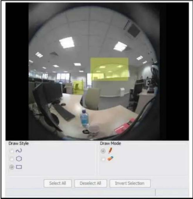
| Draw using free draw by clicking on the window and dragging to draw a shape. The area of detection is highlighted in yellow. | |
| Draw a polygon by clicking once in the window, and use the lines to form the region of interest. Click again to confirm the line. Double click when the shape is complete to finalise the detection area. The detection area is highlighted in yellow. | |
| Draw a rectangle by clicking once in the window and dragging the cursor over the camera view to highlight the area of interest. The detection area is highlighted in yellow when the mouse button is released. | |
| Select Draw when you want the draw style to draw a detection area. | |
| Select Erase when you want the draw style to erase sections of a detection area. | |
| Select when you want to select end entire camera view. | |
| Deselect All | This will remove the active selections. |
| Invert Selection | This will invert the current active selection. |
Creating a Motion Detection Alert
Create a motion detection alert on the camera.
Note
1 If the motion detection video stream is changed after the region of interest has been drawn it will be necessary to re-draw a new region.
2 If the stream settings are modified the motion detection will be disabled and it will be necessary to enable motion detection again if required.
3 Motion detection can only be enabled on a video stream that uses H.264.
Procedure 7-8 Create a Motion Detection Alert
Step Action
1 Select Setup on the Web User Interface banner to display the setup menus.
2 Select Motion Detection from the Events menu. The Fault
Actions tab displays.
3 On FW 1.04 or older When this tab is accessed you will be prompted to authorise the Motion Detection Configuration Pane applet, a Security Warning window will display as seen in Figure 7-3 Security Warning for Motion Detection.
Figure 7-3 Security Warning for Motion Detection

4 Select the I accept the risk and want to run this app check box.
Note
To prevent this applet appearing for future motion detection, change security settings in the browser.
5 Select Run.
The Motion Detection Configuration pane will be displayed.
6 Select Enable motion detection to enable Motion Detection on the camera. OR
Deselect Enable motion detection to disable Motion Detection on the camera.
7 Select the video stream to set the motion detection alert on from the Stream drop-down menu. The Motion Detection Configuration Pane will update to display the selected stream.
Refer to Procedure 5-1 Configure the video stream settings, to change settings for the video stream.
Note
If the motion detection video stream is changed after the region of interest has been drawn it will necessary to re-draw a new region on the new stream.
8 Select Edit to enable the drawing tools on the Motion Detection Configuration Pane.
9 Use the drawing tools as described in Motion Detection Configuration Pane to draw the region of interest on the pane. Multiple selections can be made.
Note
If the motion detection video stream is changed after the region of interest has been drawn it will be necessary to re-draw a new region on the new stream.
10 Select the fault action from the Action drop-down menu.
This fault action will be activated when motion is detected in the selected region of interest.
Refer to Procedure 7-6 Create a Fault Action, if a fault action has not yet been defined.
11 Select the sensitivity from the Sensitivity drop-down menu:
- Highest
- High
- Medium
- Low
- Lowest
12 Select Apply to save the changes.
- End -
Enable or Disable a Motion Detection Alert
Motion detection can be turned on and turned off when required.
Procedure 7-9 Enable or Disable a Motion Detection Alert
Step Action
1 Select Setup on the Web User Interface banner to display the setup menus.
2 Select Motion Detection from the Events menu. The Fault
Actions tab displays.
3 When this tab is accessed you will be prompted to authorize the Motion Detection Configuration Pane applet, a Security Warning window will display as seen in Figure 7-3 Security Warning for Motion Detection.
4 Select the I accept the risk and want to run this app check box.
5 Select Run.
The Motion Detection Configuration pane will be displayed.
6 Select Enable motion detection to enable Motion Detection on the camera. OR
Deselect Enable motion detection to disable Motion Detection on the camera.
7 Select Apply to save.
- End -
Scheduled Tasks
This section is only applicable to the Pro 5MP Fisheye camera. Schedule tasks to include specific situations or events; you can set up a regular schedule or a custom schedule. Schedules could be set for the camera to perform a task, Monday to Friday with a different task for weekend or holiday operation.
Note
1 Scheduled Tasks must use an Active Image source either Active Image 1, 2, 3 or 4. Refer to Procedure 5-1 Configure the video stream settings, to change settings for the video stream.
2 Scheduled tasks, alarms and manual camera control will always begin when they are selected or scheduled to start. None of these camera actions have a priority over the other.
Creating a Scheduled Task
Create a new scheduled task.
Note
Scheduled Tasks must use an Active Image source either Active Image 1, 2, 3 or 4. Refer to Procedure 5-1 Configure the video stream settings, to change settings for the video stream.
Procedure 7-10 Create a Scheduled Task
Step Action
1 Select Setup on the Web User Interface banner to display the setup menus.
2 Select Scheduled Tasks from the Events menu.
3 Select the Add Task tab. The Add
Task tab displays.
4 Enter a task name in the Name text box.
5 Select a start time from the Start Time (HH:MM) drop-down menu. Use 24hr clock.
6 Select the Task Frequency:
- Every day
- Week days
- Days of Month
If week days is selected you will be required to choose the days on which days the task will run. Select the check box beside the day to add that day to the task frequency.
If days of month is selected you will be required to enter the numerical value for the day separated by a comma. For example, to run on the 4th, 10th, 21st and 25th days of the month enter 4,10,21,25.
7 Select the pre-configured active image source from the Image Source drop-down menu. Refer to Streams on page 5-36 for further information.
8 Select the required Action:
- Preset
- Pattern
- Sequence
- Scan
- None
Note
Preset, Pattern, Sequence and Scans will only be available if the selected image source is an Active Image.
9 If an action is selected choose type of action to perform from the Action Parameter drop-down menu.
10 Select Apply.
Select the Scheduled Tasks tab to display a list of tasks currently set on the camera.
- End -
Editing a Scheduled Task
Edit the details for an existing scheduled task.
Procedure 7-11 Edit a Scheduled Task
Step Action
1 Select Setup on the Web User Interface banner to display the setup menus.
2 Select Scheduled Tasks from the Events menu. The Scheduled
Tasks tab displays.
3 Select ☐ to edit the corresponding task. The task will open in the Edit Task tab.
4 Changes can be made to the following:
- Task Name
- Start Time (HH:MM)
- Task Frequency
- Action
5 Select Apply to save the changes.
- End -
Deleting a Scheduled Task
Delete an existing scheduled task.
Procedure 7-12 Delete a Scheduled Task
Step Action
1 Select Setup on the Web User Interface banner to display the setup menus.
2 Select Scheduled Tasks from the Events menu. The
Scheduled Tasks tab displays.
3 Select the corresponding Delete check box to mark the scheduled task for deletion. Or Clear the corresponding Delete check box to keep the scheduled task.
Note
Select the Select All check box to mark all tasks for deletion.
4 Select Delete to delete the selected scheduled tasks. You will be prompted to confirm the deletion.
5 Select OK to confirm the deletion. Or Select Cancel.
- End -
Applications support allow for the upload of binary files that add custom functionality and value to the camera. Applications are uploaded through the Web User Interface. These applications are licensed by Tyco Security Products using a licensing facility.
Applications
Procedures relating to applications are included below.
Procedure 8-1 Upload an Application
Step Action
1 Select Setup on the Web User Interface banner to display the setup menus.
2 Select the Applications menu.
The Application tab displays.
3 Select Browse.
The Choose file dialog displays.
4 Navigate to the location where the application is saved.
5 Select the application file, then select Open.
6 Select Upload.
The upload process begins.
- End -
Available Applications
A list of applications currently installed and running are displayed. Each can be started, stopped and removed.
Procedure 8-2 Start, stop, or remove an application
Step Action
1 Select Setup on the Web User Interface banner to display the setup menus.
2 Select the Applications menu.
The Applications tab displays.
3 Select the corresponding Application check box to start, stop, or remove an application.
4 Select one of the following options:
a. Start to start the application running.
b. Stop to stop the application running.
c. Remove to remove the application.
- End -
License
License files for applications are uploaded using the licensing webpage. Available licenses are listed displaying their application ID and their license expiry date.
Procedure 8-3 Upload a license file
Step Action
1 Select Setup on the Web User Interface banner to display the setup menus.
2 Select License from the Applications menu.
3 Select Browse.
The Choose file dialog displays.
4 Navigate to the location where the license file is saved.
5 Select the license file, and then select Open.
6 Select Upload.
The upload process begins.
- End -
When the Security menu is selected Figure 9-1 Security Menu will be displayed.

Figure 9-1 Security Menu
The Security Menu provides access to the following camera settings and functions:
- Security Status
- Users
- HTTP/HTTPS
- IEEE 802.1x
- Firewall
- Remote Access
- Session Timeout
Security Status
This section explains how to configure security features for the camera and modify the communication protocols that are used.
Enhanced Security
Admin users can change the Security Mode of the camera from Standard Security to Enhanced Security.
Procedure 9-1 Enable Enhanced Security
Step Action
1 Select Setup on the Web User Interface banner to display the setup menus.
2 Select Security Status from the Security menu.
3 Select the Security Overview tab.
4 Check the Enable Enhanced Security check box to enable enhanced security
OR
Clear the Enable Enhanced Security check box to disable enhanced security.
Enhanced Security is disabled by default.
The Security Warning dialog appears.
5 Enter the current password in the Current Password text box.
6 Enter the new password in the New Password text box.
Note:
The password for enhanced security must meet the following requirements:
a. Be a minimum of seven characters long
b. Have at least one character from at least three of the following character groups:
i. Upper-case letters
ii. Lower-case letters
iii. Numeric characters
iv. Special characters
7 Re-enter the new password in the Confirm Password text box.
8 Click Apply.
- End -
Procedure 9-2 Disable Enhanced Security Mode
| Step | Action |
| 1 | Select Setup on the Web User Interface banner to display the setup menus. |
| 2 | Select Security Status from the Security menu. |
| 3 | Select the Security Overview tab. |
| 4 | Clear the Enable Enhanced Security check box to disable enhanced security.Note: |
| When in Enhanced Security mode, changing the security mode requires the admin account password. | |
| 5 | Click Apply. |
- End -
Setting Communication Protocols
This section explains how to modify the communication protocols that are used. The following communication protocols can be enabled: HTTP, FTP, CIFS, Dyn DNS, SMTP, HTTPS, SNMP V3, and SFTP.
Procedure 9-3 Enable/Disable Communication Protocols
| Step | Action |
| 1 | Select Setup on the Web User Interface banner to display the setup menus. |
| 2 | Select Security Status from the Security menu. |
| 3 | Select the Security Overview tab. |
| 4 | Click Edit on the Communication Protocol you want to modify. You are redirected to the individual protocol page to enable or disable the Communication Protocol.Note:When in Enhanced Security, enabling/disabling individual protocols requires the admin account password. |
- End -
Users
In this section you are able to add, change passwords and delete user accounts. There are three levels of access: admin, operator and user.
Refer to Appendix A: User Account Access for details on the features which are available to each role.
Add User
Add a new user account to allow access to the camera.
Procedure 9-4 Add a User
Step Action
1 Select Setup on the Web User Interface banner to display the setup menus.
2 Select Users from the Network menu.
3 Select the Add User tab.
The Add User tab displays.
4 Enter a User Name in the Name text box.
The username must start with a letter and can be followed by any alphanumeric values (a-z, A-Z, 0-9) and the following special characters, underscore (_), dash (-), or dot(.)
5 Select a Role:
- admin
- operator
- user
Refer to Appendix A: User Account Access for details on access areas for each role.
6 Enter a password in the Password text box.
The password must start with an alphanumeric character and is case sensitive; it can contain alphanumeric characters with a length of between 4 and 32 characters.
Note:
The password for enhanced security must meet the following requirements:
- Be a minimum of seven characters long
- Have at least one character from at least three of the following character groups:
• Upper-case letters
- Lower-case letters
- Numeric characters
- Special characters
7 Enter the same password in the Confirm Password text box.
8 Select Apply to save the settings.
- End -
Changing the User Accounts Password
Change the password of an existing user account.
Procedure 9-5 Change User Password
Step Action
1 Select Setup on the Web User Interface banner to display the setup menus.
2 Select Users from the Security menu.
3 Select the Change Password tab.
The Change Password tab displays.
4 Select the user account from the Name drop-down menu.
5 Enter the current password for the user account in the Current Password text box.
6 Enter the new password for the user account in the New Password text box.
The password is case sensitive and can contain alphanumeric characters with a length of between 4 and 32 characters.
7 Enter the same new password in the Confirm New Password text box.
8 Select Apply to save the settings.
- End -
View Current User Accounts
View a list of the current user accounts assigned to the camera.
Procedure 9-6 View User Accounts
Step Action
1 Select Setup on the Web User Interface banner to display the setup menus.
2 Select Users from the Security menu.
The Users tab displays.
3 The current user accounts assigned to the camera will be displayed.
- End -
Delete a User Account
Delete a user account from the camera.
Note
The default 'admin' account cannot be deleted.
Procedure 9-7 Delete a User Account
Step Action
1 Select Setup on the Web User Interface banner to display the setup menus.
2 Select Users from the Security menu.
The Users tab displays.
3 Select ☐ to delete the corresponding user account.
You will be prompted to confirm the deletion.
4 Select OK to delete.
Or
Select Cancel.
- End -
HTTP/HTTPS
Upload a HTTP/HTTPS Certificate
The camera will automatically create an SSL certificate file to use for HTTPS. It is possible to upload a custom SSL certificate if validation is required.
Procedure 9-8 Add a HTTP/HTTPS Certificate
Step Action
1 Select Setup on the Web User Interface banner to display the setup menus.
2 Select HTTP/HTTPS from the Security menu.
3 Select the HTTPS Certificate tab. The HTTP/HTTPS Certificate tab displays.
4 Select Browse. The Choose file dialog will be displayed.
5 Navigate to the location where the HTTP/HTTPS certificate has been saved. Select the backup file then select the Open button.
Note
The certificate needs to match the camera 'host name'.
6 Select Upload.
You will be prompted to confirm that you would like to upload the HTTP/HTTPS certificate.
7 Select OK to confirm the upload.
- End -
Delete a Certificate
If you delete the existing certificate it will be replaced by a temporary substitute. The current browser session will be lost and you will be required to log back in to the camera Web User Interface.
Procedure 9-9 Delete a HTTP/HTTPS Certificate
Step Action
1 Select Setup on the Web User Interface banner to display the setup menus.
2 Select HTTP/HTTPS from the Security menu.
3 Select the HTTP/HTTPS tab.
The HTTP/HTTPS tab displays.
4 Select Delete.
The camera will display a “Restarting HTTPS Service” page with a progress bar showing the deletion progress.
5 When complete the camera will return to the log in page.
6 Refer to Procedure 3-1 Log in to the camera, for information on logging in to the camera.
- End -
IEEE 802.1x
The IEEE 802.1x security feature provides port based network access control i.e. securing corporate networks from the attachment of unauthorized devices.
Authentication is carried out through use of the Extensible Authentication Protocol or EAP. Both PEAP and TLS methods are supported.
Upload a HTTP/HTTPS Certificate
The camera will automatically create an SSL certificate file to use for HTTPS. It is possible to upload a custom SSL certificate if validation is required.
Procedure 9-10 Configure IEEE 802.1x Security
Step Action
1 Select Setup on the Web User Interface banner to display the setup menus.
2 Select IEEE 802.1x from the Security menu.
The General tab displays.
Security Status
3 Select the Enable IEEE 802.1x check box to enable IEEE802.1x security OR Clear the Enable IEEE 802.1x check box to disable IEEE802.1x security
4 Select the EAPOL Version from the drop-down menu.
5 Select the EAP Method using the radio buttons.
6 Enter the EAP Identity name in the EAP identity textbox.
7 Select Upload to navigate to the CA Certificate location. The Choose file dialog will be displayed.
8 Navigate to the location where the certificate has been saved. Select the file and select Open.
9 Select Upload. The upload process will start.
10 If PEAP is selected: Enter the required PEAP password. OR
If TLS is selected:
a Select Upload to navigate to the Client certificate location. The Choose file dialog will be displayed.
b Navigate to the location where the certificate has been saved.
c Select the file and select Open.
d Select Upload. The upload process will start.
e Enter the required Private Key Password.
- End -
Firewall
Configure the Basic Filtering and Address Filtering for the Firewall.
Basic Filtering
Enable or disable basic filtering for the camera this includes:
• ICMP (Internet Control Message Protocol) Blocking
- RP (Reverse Path) Filtering
• SYN Cookie Verification.
Procedure 9-11 Enable/Disable Basic Filtering
Step Action
1 Select Setup on the Web User Interface banner to display the setup menus.
2 Select Firewall from the Security menu.
The Basic Filtering tab displays.
3 Select the ICMP Blocking check box to enable ICMP blocking.
Or
Deselect the ICMP Blocking check box to disable ICMP blocking.
The default setting is 'Disabled'.
4 Select the RP Filtering check box to enable the RP filtering.
Or
Deselect the RP Filtering check box to disable.
The default setting is 'Disabled'.
5 Select SYN Cookie Certification check box to enable SYN cookie certification.
Or
Deselect the SYN Cookie Certification check box to disable.
The default setting is 'Disabled'.
- End -
Address Filtering
Configure the IP or MAC addresses which are denied access to the camera.
Procedure 9-12 Enable/Disable and configure Address Filtering
Step Action
1 Select Setup on the Web User Interface banner to display the setup menus.
2 Select Firewall from the Security menu.
3 Select the Address Filtering tab.
The Address Filtering tab displays.
4 Select the Address Filtering check box to enable address filtering.
Or
Deselect the Address Filtering check box to disable address filtering.
The default setting is 'Disabled'.
5 If address filtering has been enabled:
a Enter an IP or MAC Address to deny in the IP or MAC Address text box in the following format xxx.xxx.xxx.xxx.
Note
CIDR (Classless Inter-Domain Routing) is supported when using address filtering.
If using a CIDR address use the following format xxx.xxx.xxx.xxx/xx.
b Select Add.
6 Select Apply to save the settings.
- End -
Editing an Address Filter
Edit an existing address filter.
Procedure 9-13 Edit an Address Filter
Step Action
1 Select Setup on the Web User Interface banner to display the setup menus.
2 Select Firewall from the Security menu.
3 Select the Address Filtering tab.
The Address Filtering tab displays.
4 Select □ to edit the corresponding address filter.
5 Select Apply to save the changes to the address filter.
6 Edit the IP or MAC Address in the IP or MAC Address text box.
7 Select Add to save the changes.
Or
Select Cancel.
- End -
Deleting an Address Filter
Delete an existing address filter.
Procedure 9-14 Delete an Address Filter
Step Action
1 Select Setup on the Web User Interface banner to display the setup menus.
2 Select Firewall from the Security menu.
3 Select the Address Filtering tab.
The Address Filtering tab displays.
4 Select ☐ to delete the corresponding address filter.
- End
Remote Access
SSH Enable
Enables Secure Shell access into the camera, if remote access is permitted by the camera network. This will also enable American Dynamics Level 3 Technical Support to diagnose any problems on the camera.
Note
It is recommended to keep SSH Enable disabled. This function should only be enabled this when it is requested by American Dynamics Level 3 Technical Support.
Procedure 9-15 Configure SSH
Step Action
1 Select Setup on the Web User Interface banner to display the setup menus.
2 Select Security, and then select Remote Access.
The Remote Access tab displays.
3 Select the SSH Enable check box to enable SSH.
Or
Deselect SSH Enable check box to disable SSH.
The default setting is 'Disabled'.
- End -
ONVIF
The Web User Interface allows ONVIF functionality to be managed at a high level. ONVIF Discovery Mode and User Authentication can be enabled or disabled.
- ONVIF Discovery Mode allows enabling or disabling discovery of the camera via ONVIF.
- ONVIF User Authentication allows the camera to accept ONVIF commands from all users or only authenticated users. Enabling User Authentication ensures the camera will only execute commands from authenticated users.
The separation of Discovery Mode and User Authentication allows the camera to be set up in a configuration that suits requirements for the network and users. The preferred discovery method for the camera is Illustra Connect, and this utilizes ONVIF discovery. It is therefore recommended that ONVIF Discovery Mode is always enabled.
ONVIF Discovery Mode
Enable or disable ONVIF discovery on the camera.
Procedure 9-16 Enable/Disable ONVIF Discovery Mode
Step Action
1 Select Setup on the Web User Interface banner to display the setup menus.
2 Select Remote Access from the Security menu.
The Remote Access tab displays.
3 Select the ONVIF Discovery Mode check box to enable ONVIF Discovery Mode.
Or
Deselect ONVIF Discovery Mode check box to disable ONVIF Discovery Mode.
The default setting is 'Enabled'.
- End -
ONVIF User Authentication
Note
To utilize ONVIF User Authentication, there must be at least one admin level user in the ONVIF service.
When in Enhanced Security mode, editing ONVIF User Authentication requires the admin account password.
Procedure 9-17 Enable/Disable ONVIF User Authentication
Step Action
1 Select Setup on the Web User Interface banner to display the setup menus.
2 Select Remote Access from the Security menu.
The Remote Access tab displays.
3 Select the ONVIF User Authentication check box to enable ONVIF User Authentication. Or
Deselect ONVIF User Authentication check box to disable ONVIF User Authentication.
The default setting is 'Enabled'.
- End -
Session Timeout
Session timeout specifies the number of minutes that a web session can remain idle before it is automatically terminated.
Procedure 9-18 Set a Session Timeout time
Step Action
1 Select Setup on the Web User Interface banner to display the setup menus.
2 Select Session Timeout from the Security menu.
The Session Timeout tab displays.
3 Use the slider bar to select the Session Timeout (mins).
The default setting is 60 minutes.
- End -
When the Network menu is selected Figure 10-1 Network Menu will be displayed.
Figure 10-1 Network Menu
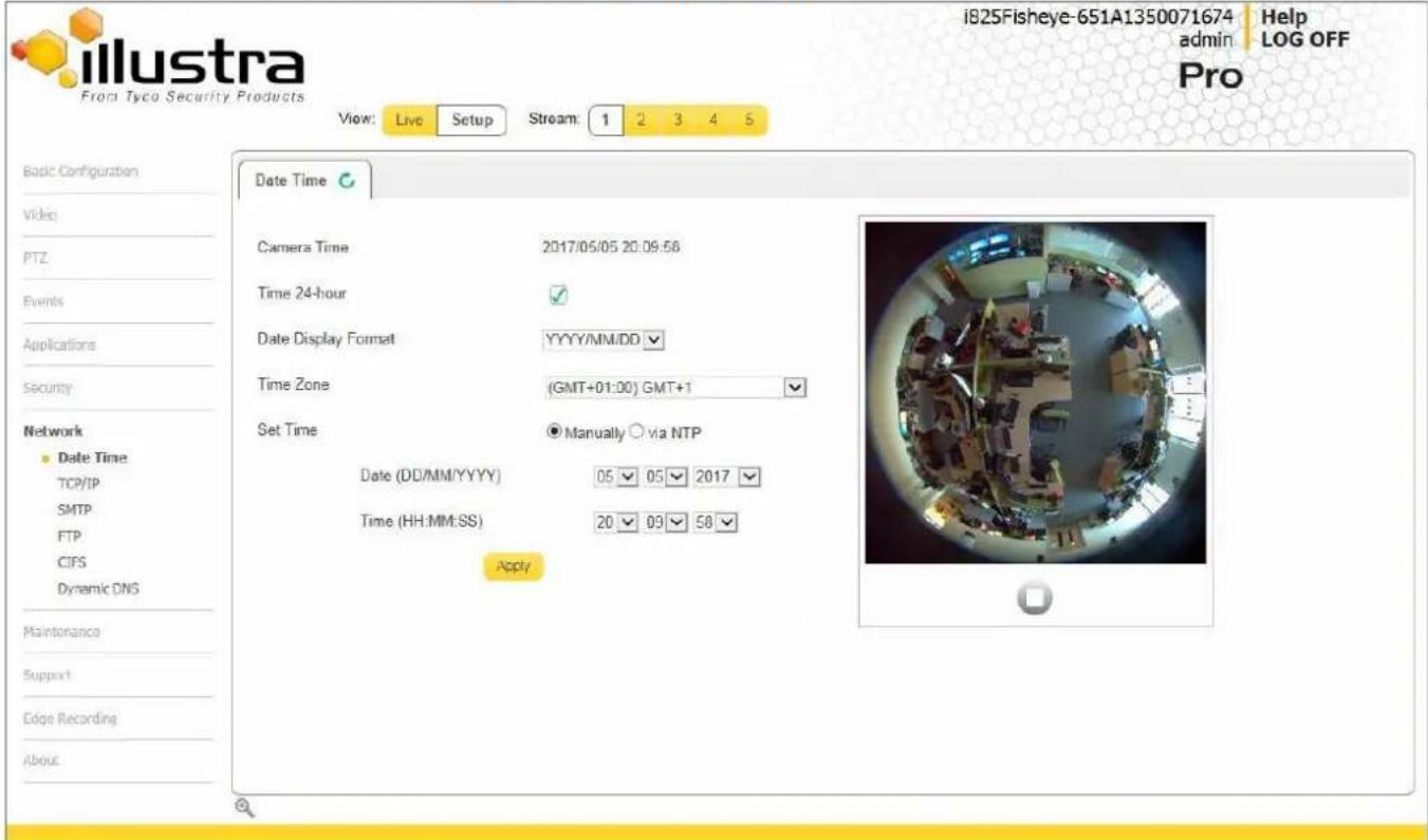
The Network Menu provides access to the following camera settings and functions:
- Date Time
- TCP/IP
- SMTP
- FTP
• CIFS - Dynamic DNS
Date Time
Set the date and time for the camera manually or via NTP.
Setting Date Time
Configure the date and time settings on the camera.
Procedure 10-1 Configuring the Date and Time
Step Action
1 Select Setup on the Web User Interface banner to display the setup menus.
2 Select Date Time from the Network menu.
The Date Time tab displays.
3 Select the Time 24-hour check box to enable the 24-hour clock.
Or
Deselect the Time 24-hour check box to enable the 12-hour clock.
The default setting is '24-hour'.
4 Select the Date Display Format from the drop-down menu:
- DD/MM/YYYY
- MM/DD/YYYY
- YYYY/MM/DD
The default setting is 'YYYY/MM/DD'.
5 Select the Time Zone from the drop-down menu.
The default setting is ‘(GMT-05:00) Eastern Time (US & Canada)
6 Select the Set Time setting by selecting the radio buttons:
- Manually
• via NTP
The default setting is 'Manually'.
7 If you select Manually in step 5:
a Select the Date (DD/MM/YYYY) using the drop-down menus.
b Select the Time (HH:MM:SS) using the drop-down menus.
8 If you select via NTP in step 5:
a Enter the NTP Server Name in the text box.
9 Select Apply to save the settings.
- End -
TCP/IP
Configure the IPv4 and IPv6 settings on the camera.
IPv4
Configure the IPv4 settings for the camera.
Procedure 10-2 Configure the IPv4 Settings
Step Action
1 Select Setup on the Web User Interface banner to display the setup menus.
2 Select TCP/IP from the Network menu. The IPv4 tab displays.
3 Select the Enable DHCP check box to enable DHCP and disable manual settings. Or
Deselect Enable DHCP to disable DHCP and allow manual settings to be entered. The default setting is 'Enabled'.
4 If Enable DHCP has been disabled:
a Enter the IPv4 Address in the IPv4 Address text box in the form xxx.xxx.xxx.xxx. The default setting is '192.168.1.168'
b Enter the Network Mask in the Network Mask text box xxx.xxx.xxx.xxx. The default setting is '255.255.255.0'
c Enter the Gateway IP address in Gateway text box xxx.xxx.xxx.xxx.
d Enter the Primary DNS Server in the Primary DNS Server text box xxx.xxx.xxx.xxx.
e Enter the Secondary DNS Server in the Secondary DNS Server text box xxx.xxx.xxx.xxx.
5 Select Apply to save the settings
- End -
IPv6
Enable IPv6 on the camera.
Procedure 10-3 Enable/Disable IPv6
Step Action
1 Select Setup on the Web User Interface banner to display the setup menus.
2 Select TCP/IP from the Network menu.
3 Select the IPv6 Enable check box to enable IPv6 on the camera.
Or
Deselect the IPv6 Enable check box to disable IPv6 on the camera.
The default setting is 'enabled'.
If IPv6 is enabled the Link Local and DHCP address will be displayed beside 'Current IPv6 Addresses' if available.
- End -
DHCP
On initial camera startup, and after a hardware factory reset, Dynamic Host Configuration Protocol (DHCP) is enabled by default and remains enabled until the camera receives until the camera receives either a DHCP address or is assigned a Static IP address.
Procedure 10-4 Enable DHCP
Step Action
1 Select Setup on the Web User Interface banner to display the setup menus.
2 Select the TCP/IP tab from the Network menu.
3 Select the Enable DHCP check box to enable DHCP and disable manual settings.
4 Select Apply to save the settings.
The camera will search for a DHCP server. If one is found it will connect to that server. If no connection is made to a DHCP server within two minutes, the camera goes to the default IP address 192.168.1.168, but continues to search for a DHCP address.
Select the Enable DHCP check box to enable DHCP and disable manual settings. Or
Deselect Enable DHCP to disable DHCP and allow manual settings to be entered. The default setting is 'Enabled'.
Note
If the camera is assigned a Static IP address prior to DHCP being enabled, the camera first reboots for approximately 30 seconds and then remains accessible at its Static IP until a connection is made to a DHCP server.
- End -
Procedure 10-5 Disable DHCP
Step Action
1 Select Setup on the Web User Interface banner to display the setup menus.
2 Select the TCP/IP tab from the Network menu.
3 Clear the Enable DHCP check box to disable DHCP and allow manual settings to be entered. The default setting is 'Enabled'.
4 If Enable DHCP has been disabled:
a. Enter the IPv4 Address in the IPv4 Address text box in the form
XXX.XXX.XXX.XXX.
The default setting is '192.168.1.168'
b. Enter the Network Mask in the network Mask text box xxx.xxx.xxx.xxx. The default setting is '255.255.255.0'
c. Enter the Gateway IP address in Gateway text box xxx.xxx.xxx.xxx.
d. Enter the Primary DNS Server in the Primary DNS Server text box xxx.xxx.xxx.xxx.
5 Select Apply to save the settings.
- End -
SMTP
Configure the SMTP settings to allow e-mail alerts to be sent from the camera when a motion detection alert is triggered.
Note
SMTP settings can also be configured through the Events > Fault Settings menu.
Configure SMTP
SMTP settings must be configured to enable email alerts when using motion alerts.
Procedure 10-6 Configure SMTP Settings
Step Action
1 Select Setup on the Web User Interface banner to display the setup menus.
2 Select SMTP from the Network menu.
The SMTP tab displays.
3 Enter the IP Address of the mail server in the Mail Server text box.
4 Enter the server port in the Server Port text box.
The default setting is '25'.
5 Enter the from email address in the From Address text box.
6 Enter the email address to send email alerts to in the Send Email to text box.
7 Select the Use authentication to log on to server check box to allow authentication details to be entered.
Or
Deselect the Use authentication to log on to server to disable authentication.
The default setting is 'Disabled'.
Note:
When in Enhanced Security mode, enabling SMTP requires the admin account password.
8 If 'Use authentication to log on to server' check box has been selected:
a Enter the username for the SMTP account in the Username text box.
b Enter the password for the SMTP account in the Password text box.
9 Select Apply to save the settings.
Note
Refer to Test SMTP Settings, to confirm that the SMTP settings are working as expected.
- End -
Test SMTP Settings
Test the SMTP settings that have been configured. For more information, see Procedure 10-6 Configure SMTP Settings.
Procedure 10-7 Test the SMTP Settings
Step Action
1 Select Setup on the Web User Interface banner to display the setup menus.
2 Select SMTP from the Network menu. The SMTP
tab displays.
If Procedure 10-6 Configure SMTP Settings have been configured, a Test button will be displayed.
3 Select Test.
A sample email will be sent to the specified email address to confirm that SMTP settings are correct.
The camera will display a message confirming that the transfer was either successful or failed.
- End -
FTP
Configure the FTP settings for the FTP server. This is required to send video files from triggered motion detection alerts.
Note
FTP settings can also be configured via the Events > Fault Settings menu.
Configuring FTP Server Settings
FTP must be configured to enable FTP video alerts when using motion detection.
Procedure 10-8 Configure FTP Server Settings
Step Action
1 Select Setup on the Web User Interface banner to display the setup menus.
2 Select FTP from the Network menu.
The FTP tab displays.
3 Enter the IP address of the FTP Server in the FTP Server text box.
4 Enter the FTP port in the FTP Port text box.
The default setting is 21.
5 Select the Use authentication to log on to server check box to allow authentication details to be entered.
Or
Deselect the Use authentication to log on to server to disable authentication.
The default setting is 'Disabled'.
Note:
When in Enhanced Security mode, enabling FTP requires the admin account password.
6 If Use authentication to log on to server check box has been selected:
a Enter the FTP username in the Username text box.
b Enter the FTP password in the Password text box.
7 Select Apply to save the settings.
Note
Refer to Procedure 10-7 Test the SMTP Settings to confirm that the FTP settings are working as expected.
- End -
Test FTP Settings
Test the FTP settings that have been configured.
Procedure 10-9 Test the FTP Settings
Step Action
1 Select Setup on the Web User Interface banner to display the setup menus.
2 Select FTP from the Network menu.
The FTP tab displays.
If Procedure 10-8 Configure FTP Server Settings have been configured a Test button will be displayed.
3 Select Test.
A sample text file will be sent to the specified FTP destination to confirm that FTP settings are correct.
- End -
Dynamic DNS
Dynamic DNS is supported for updating, in real time a changing IP address on the Internet to provide a persistent domain name for a resource that may change location on the network. RFC 2136 Dynamic Updates in the Domain Name System. In this situation the camera talks only to the DHCP server and the DHCP server is responsible for updating the DNS server. The camera sends its hostname to the DHCP server when requesting a new lease and the DHCP server updates the DNS records accordingly. This is suitable for an intranet style configuration where there is an internal DHCP and DNS service and the user wants only to access their camera within their own network.
By default, when making a DHCP request the camera will transmit its hostname as part of the DHCP request. This option is not user configurable. The cameras hostname matches the configurable parameter "camera name" on the web user interface. Any DHCP request will contain the cameras hostname for use of the DHCP server to forward to an appropriate DNS server.
Dynamic DNS
Configure the Dynamic DNS settings for the camera.
Procedure 10-10 Configure Dynamic DNS
Step Action
1 Select Setup on the Web User Interface banner to display the setup menus.
2 Select Dynamic DNS from the Network
menu. The Dynamic DNS tab displays.
3 Select the Service Enable check box to enable Dynamic DNS. Or Deselect Service
Enable check box to disable Dynamic DNS. The default setting is 'Disabled'.
4 If Service Enable has been enabled:
a Enter the Camera Alias in the text box.
b Select a Service Provider from the drop-down list:
•dyndns.org
•easydns.com
•no-ip.com
•zerigo.com
•dynsip.org
•tzo.com
c Enter a Username in the text box.
d Enter a Password in the text box.
e Enter Service Data in the text box.
Select Apply to save the settings.
- End -
When the Maintenance menu is selected Figure 11-1 Maintenance Menu will be displayed.
Figure 11-1 Maintenance Menu
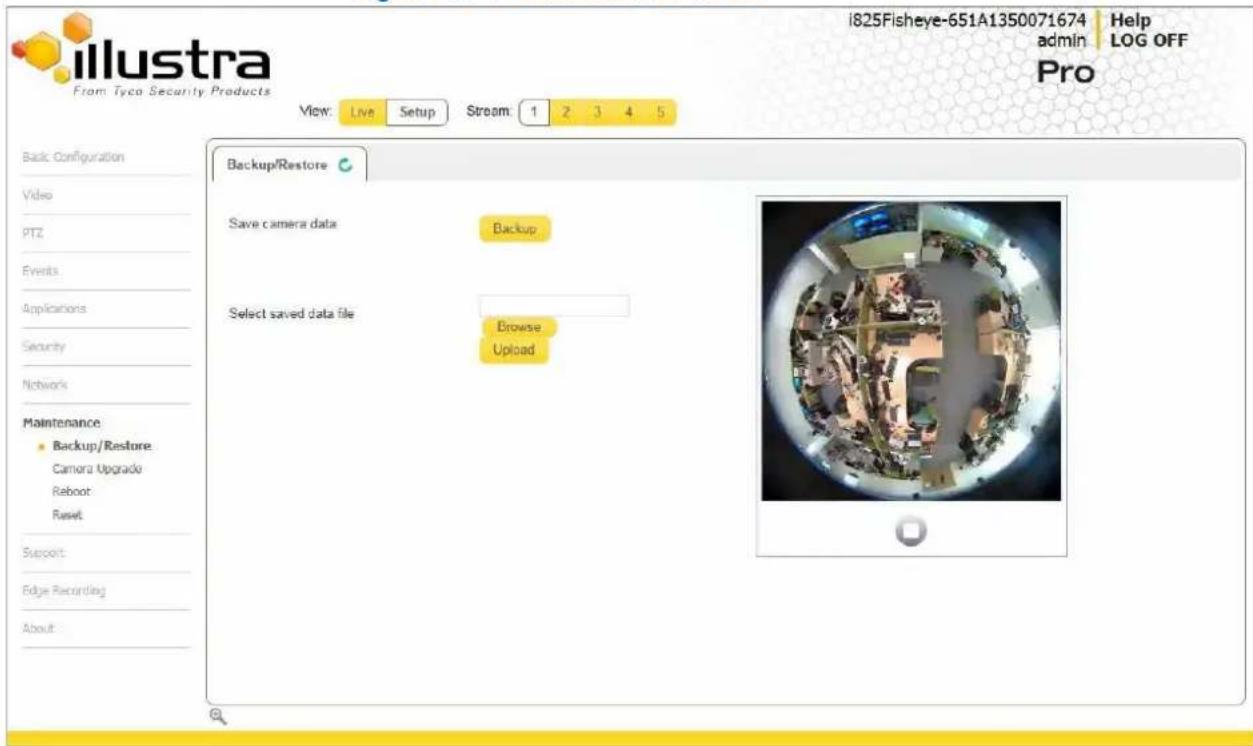
The Maintenance Menu provides access to the following camera settings and functions:
- Backup/Restore
- Camera Upgrade
- Reboot
- Reset
Backup/Restore
Backup camera data and restore from a previously saved data file.
Save Camera Data
The configuration settings of the camera can be saved to a data file. The data file can be saved to a specified location and used to restore the camera configuration.
Note
A saved backup data file created on a camera is camera specific and cannot be used to restore the settings on a different camera.
Procedure 11-1 Backup Camera Data
Step Action
1 Select Setup on the Web User Interface banner to display the setup menus.
2 Select Backup/Restore from the Maintenance menu.
The Backup/Restore tab displays.
3 Select Backup.
You will be prompted to save the backup file.
4 Select a location to save the backup file.
5 Select Save.
- End -
Restore Camera Data
The camera has the ability to restore its configuration from a previously saved configuration file.
Note
A saved backup data file created on a camera is camera specific and cannot be used to restore the settings on another camera.
1 Select Setup on the Web User Interface banner to display the setup menus.
2 Select Backup/Restore from the Maintenance menu.
The Backup/Restore tab displays.
3 Select Browse.
The Choose file dialog will be displayed.
4 Navigate to the location where the backup file has been saved.
Select the backup file then select the Open button.
5 Select Upload.
The file will transfer to the camera and a "Camera Restore" page with a progress bar will be displayed.
6 The Log in page will be displayed.
Refer to Procedure 3-1 Log in to the camera for information on logging back into the camera Web User Interface.
- End -
Camera Upgrade
Upgrade Camera Firmware
The camera can be upgraded using firmware provided by American Dynamics. Alternatively, the camera can also be upgraded using Illustra Connect. Refer to the Illustra Connect User Guide for further information.
Note
All existing camera settings are maintained when the firmware is upgraded.

Caution
You should only use firmware that has been provided by American Dynamics. Using any other firmware may cause a malfunction and damage the camera.
Procedure 11-3 Upgrade Camera Firmware
Step Action
1 Select Setup on the Web User Interface banner to display the setup menus.
2 Select Camera Upgrade from the Maintenance menu.
The Camera Upgrade tab displays.
3 Select Browse.
The Choose file to Upload dialog will be displayed.
4 Navigate to the location where the firmware file has been saved.
Select the backup file then select the Open button.
5 Select Upload.
The file transfer will begin. Do not disconnect power to the camera during the upgrade process. The camera restarts automatically after the updates have been completed, this can take from 1 to 10 minutes.
6 The Log in page will be displayed.
Refer to Procedure 3-1 Log in to the camera for information on logging back into the camera Web User Interface.
- End -
Reboot
To perform a physical reboot of the camera, refer to Procedure 16-1 Reboot the camera using the Reboot/Reset Switch.
Rebooting the Camera
Perform a reboot of the camera.
Procedure 11-4 Reboot the Camera
Step Action
1 Select Setup on the Web User Interface banner to display the setup menus.
2 Select Reboot from the Maintenance menu.
The Reboot tab displays.
3 Select Reboot.
You will be prompted to confirm the camera reboot.
4 Select OK to confirm. The Web User Interface will display a "Camera Rebooting" page with a progress bar showing the reboot progress.
When the camera is restarted it will take 2 - 3 minutes until it is online and ready to be accessed and controlled.
Or
Select Cancel.
5 The Log in page will be displayed.
Refer to Procedure 3-1 Log in to the camera for information on logging back into the camera Web User Interface.
- End -
Reset
To perform a physical reset of the camera, refer to Procedure 16-2 Reset the Camera to Factory Default Settings using the Reset/Reboot Switch.
Reset the Camera to Factory Default Settings
Restore the settings on the camera to factory default.
Note
Network settings, presets, patterns and sequences can be retained if required.
Procedure 11-5 Resetting the Camera
Step Action
1 Select Setup on the Web User Interface banner to display the setup menus.
2 Select Reset from the Maintenance menu.
The Reset tab displays.
3 Select the Preserve networking settings check box to retain the current network settings during the camera reset.
Or
Deselect the Preserve networking settings to restore the default networking settings.
The default setting is 'Enabled'.
4 Select the Preserve presets, patterns and sequences check box to retain the current presets, patterns and sequences during the camera reset.
Or
Deselect the Preserve presets, patterns and sequences to remove existing presets, patterns and sequences.
The default setting is 'Enabled'.
5 Select the Preserve applications check box to retain the current applications during the camera reset.
Or
Deselect the Preserve applications check box to remove applications during the camera reset.
The default setting is 'Enabled'.
6 Select Reset
You will be prompted to confirm the camera reset.
7 Select OK to confirm. The Web User Interface will display a "Camera Resetting" page with a progress bar showing the reboot progress.
When the camera is restarted it will take 2 - 3 minutes until it is online and ready to be accessed and controlled.
Or
Select Cancel.
8 The Log in page will be displayed.
Refer to Procedure 3-1 Log in to the camera for information on logging back into the camera Web User Interface.
- End -
When the Support menu is selected Figure 12-1 Support Menu will be displayed.
Figure 12-1 Support Menu
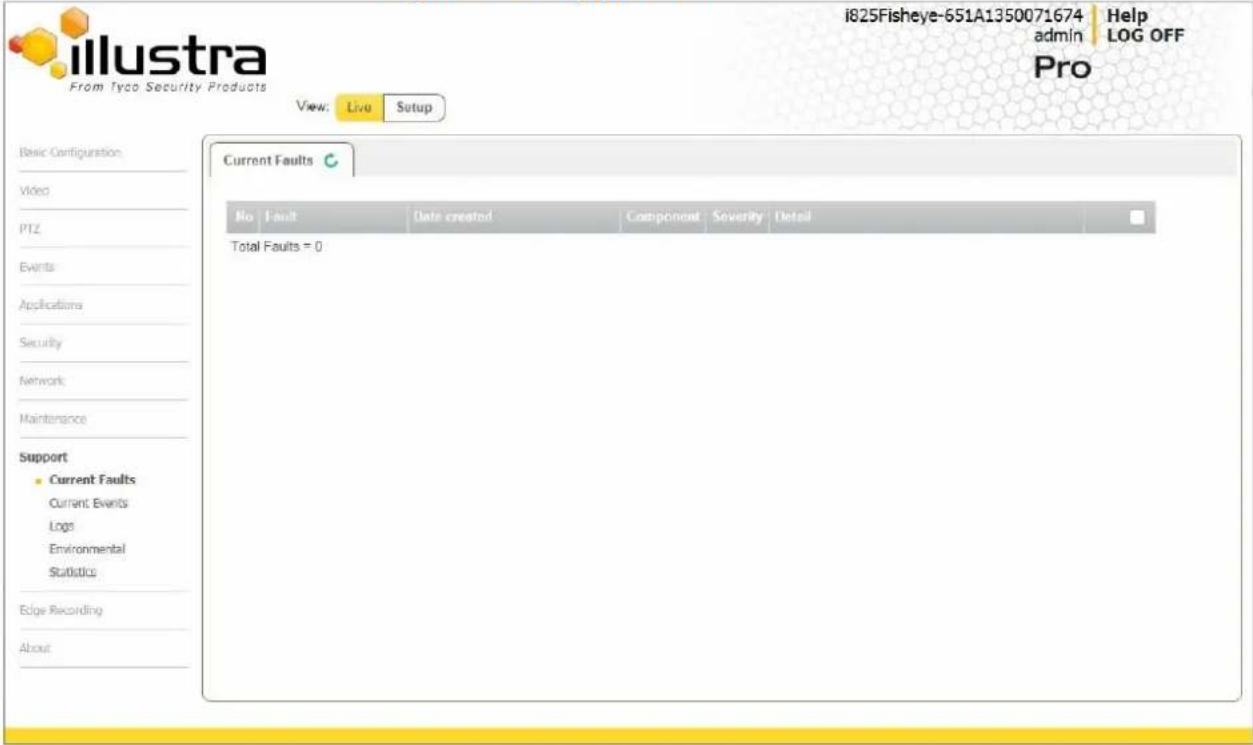
The Support Menu provides access to the following camera information:
- Current Faults
- Current Events
- Logs
- Environmental
• Statistics
Current Faults
Any system or environmental faults experienced by the camera are displayed in current faults.
Current Faults
When Current Faults is selected information will be displayed on the following:
-
- details the fault index.
- Fault - a description of the fault.
- Date created - the time and date when the fault occurred.
- Component - internal software component that raised the fault either DIOM (Digital Input Output Monitor) or ENVM (Environmental Monitor).
- Severity - indicates how serious the fault is. The following are supported, in increasing order of severity, Clear, Warning, Critical and Error.
• Detail - extra information that supplements the fault description. - Delete -remove the fault from the fault table.
Fault Details
System Faults
The following system faults may be raised:
- DiskUsage (Warning) - this warning is raised when the disk utilisation rises above the threshold value “threshold2” held in SYSM.conf. Once an alarm is generated and the disk utilization decreases 1% below the threshold value, the fault is then automatically cleared. The default threshold value is 80%.
- PowerSupplyAlarm (Error) - this fault is raised when one or more of the internal DC power supplies voltage level is either too high or too low. Once an alarm is generated and the DC power voltage goes back into the proper range, the fault is then automatically cleared.
ENVM (Environmental Monitor) Component
The following environmental faults can be raised by the ENVM (Environmental Monitor) component:
- TemperatureTooHigh (Warning) - this fault is raised when the internal temperature of the enclosure is equal to or exceeds the value MAX_TEMPERATURE held in ENVM.conf. Once an alarm is generated and the temperature drops to a level 1 degree below the MAX_TEMPERATURE value the fault is then automatically cleared. This is to avoid transient changes in temperature around the threshold.
- TemperatureTooLow (Warning) - a fault is raised when the internal temperature of the enclosure is equal to or is below the value MIN_TEMPERATURE held in ENVM.conf. Once an alarm is generated and the temperature drops to a level 1 degree above the MIN_TEMPERATURE value the fault is then automatically cleared. This is to avoid transient changes in temperature around the threshold.
Procedure 12-1 Display Current Faults
Step Action
1 Select Setup on the Web User Interface banner to display the setup menus.
2 Select Current Faults from the Support menu.
The current faults tab displays.
- End -
Procedure 12-2 Delete Current Faults
Step Action
1 Select Setup on the Web User Interface banner to display the setup menus.
2 Select Current Faults from the Support menu.
The current faults tab displays.
3 Select the corresponding Delete check box to mark the fault for deletion.
Or
Deselect the corresponding Delete check box to keep the fault.
Note
Select the Select All check box to mark all faults displayed in the list for deletion.
4 Select Delete to delete the selected faults.
You will be prompted to confirm the deletion.
5 Select OK to confirm the deletion.
Or
Select Cancel.
- End -
Current Events
When motion detection is enabled resulting alarms are displayed in current events. The following will be displayed:
-
- details the event index.
- Event - this will be listed as 'MotionDetected'.
- Date created - the time and date when the motion detection was triggered.
- Component - internal software component that raised the fault for a motion detection alert. This will be listed as ANALYTICS.
- Severity - indicates how serious the fault is. Motion detection alerts are listed as 'Warning'.
- Detail - extra information that supplements the motion detection alert.
- Delete -remove the motion detection alert notification from the fault table.
Procedure 12-3 Display Current Events
Step Action
1 Select Setup on the Web User Interface banner to display the setup menus.
2 Select Current Events from the Support menu.
The Current Events tab displays.
Triggered motion detection alerts will be displayed.
- End -
Procedure 12-4 Delete Current Events
Step Action
1 Select Setup on the Web User Interface banner to display the setup menus.
2 Select Current Events from the Support menu.
The current events tab displays.
3 Select the corresponding Delete check box to mark the motion detection alert for deletion. Or
Deselect the corresponding Delete check box to keep the motion detection alert.
Note
Select the Select All check box to mark all motion detection alerts displayed in the list for deletion.
4 Select Delete to delete the selected motion detection alerts.
You will be prompted to confirm the deletion.
5 Select OK to confirm the deletion. Or
- End -
Logs
Information is provided on system and boot logs created by the camera.
System Log
The system log gives the most recent messages from the unix /var/log/messages file. Information will include the following:
- Messages about system behavior such as process startup/shutdown.
- Warnings about recoverable problems that processes encounter.
- Error messages where processes encounter problems they cannot fix; note that this does not mean that the process will not continue to work; only that it encountered an issue it could do nothing about.
Procedure 12-5 Display System Log
Step Action
1 Select Setup on the Web User Interface banner to display the setup menus.
2 Select Logs from the Support menu.
The System Log tab displays.
3 Select Refresh to refresh the log for the most up-to-date information.
- End -
Procedure 12-6 System Log Filter
Step Action
1 Select Setup on the Web User Interface banner to display the setup menus.
2 Select Logs from the Support menu.
The System Log tab displays.
3 Enter the number of lines of the log file you would like to view in the Lines text box.
4 Enter the word or phrase that you would like to search for in the Filter text box.
5 Select Refresh to refresh the log for the most up-to-date information.
- End -
Boot Log
The Boot log is a log of the Linux operating system boot processes and will only be useful to American Dynamics support engineers who require additional information on the device.
Procedure 12-7 Display Boot Log
Step Action
1 Select Setup on the vbanner to display the setup menus.
2 Select Logs from the Support menu.
3 Select the Boot Log tab. The
Boot Log tab displays.
4 Select Refresh to refresh the log for the most up-to-date information.
- End -
Procedure 12-8 Boot Log Filter
Step Action
1 Select Setup on the Web User Interface banner to display the setup menus.
2 Select Logs from the Support menu.
3 Select the Boot Log tab. The
Boot Log tab displays.
4 Enter the number of lines of the log file you would like to view in the Lines text box.
5 Enter the word or phrase that you would like to search for in the Filter text box.
6 Select Refresh to refresh the log for the most up-to-date information.
- End -
Environmental
Environmental Information
When Environmental is selected information will be displayed on the following:
- Internal Temperature
Procedure 12-9 Display General Information
Step Action
1 Select Setup on the Web User Interface banner to display the setup menus.
2 Select Environmental from the Support menu.
The Environmental tab displays.
- End -
Statistics
This provides statistical information on the camera.
Statistics
When Statistics is selected information will be displayed on the following:
- Uptime (days-hrs:mins)
- User Resets
- Power Resets
- Total ROM (MByte)
- Total RAM (MByte)
- Free RAM (MByte)
- Operating Time (days-hrs:mins)
Procedure 12-10 Display General Information
Step Action
1 Select Setup on the Web User Interface banner to display the setup menus.
2 Select Statistics from the Information menu.
The general information tab displays.
- End -
When the Edge Recording menu is selected the Figure 13-1 Edge Recording Menu displays.
Figure 13-1 Edge Recording Menu

The Edge Recording Menu provides access to the following camera settings and functions:
• SD Card Management
- Record Settings
- Event Download
SD Card Management
Edge recording provides the ability to save recorded video to a SD card. Video can be configured to be recorded based on an event. Without a SD card, current faults display on camera if an alarm is triggered. When Model is selected information will be displayed on the following:
- Current fault notifications displayed on camera if an alarm is triggered
• Video/Audio and screenshots are saved to the SD card - SMTP notifications can be sent
- FTP uploads of video can be sent
- Audio can be played through the Audio out port
Inserting the SD Card
When inserting an SD card it is essential that the camera is rebooted. The camera is mounted and unmounted through the Web User Interface.
Note
Select the Select All check box to mark all motion detection alerts displayed in the list for deletion.
Procedure 13-1 Insert the SD Card by powering down the camera
Step Action
- Turn off the camera by disconnecting the power supply.
- Insert the SD card into the camera.
- Reconnect the power supply and power up the camera.
- End -
Procedure 13-2 Mount the SD Card using the Web User Interface to reboot the camera
Step Action
1 Insert the MicroSD card into the camera.
2 Select Setup on the Web User Interface banner to display the setup menus.
3 Select SD Card Management menu from the Edge Recording menu.
4 Select Mount.
- End -
Removing the MicroSD card
If at any stage you need to remove the MicroSD card from the camera, one of the following procedures should be used:
- Remove the SD Card by powering down the camera. Use this procedure if you don't have access to the Web User Interface and are unable to mount the microSD card before removal.
- Unmount the SD Card for removal. Use this procedure when you are unable to access the power supply to the camera.
Note
Refer to the Quick Reference Guide supplied with the product for details on how to remove the housing assembly and gain access to the camera.
Procedure 13-3 Remove the MicroSD card by powering down the camera
Step Action
- Turn off the camera by disconnecting the power supply.
Note
AVI clips are not available on the camera until the MicroSD Card has been inserted and the camera rebooted.
- Reconnect the power supply and power up the camera.
- End -
Procedure 13-4 Unmount the MicroSD Card for removal
Step Action
1 Select Setup on the Web User Interface banner to display the setup menus.
2 Select SD Card Management from the Edge Recording menu.
3 Select Unmount.
You are prompted to confirm the unmounting.
4 Select OK to confirm
OR
Select Cancel.
5 Remove the SD card from the camera.
AVI clips are not available on the camera until the SD card has been inserted and mounted.
- End -
Record settings
Select which video stream to use for alarm video and configure pre and post event durations for the playable video clip. The camera can record video generated from MD, face detection and DIO events.
Procedure 13-5 Configure record settings
Step Action
1 Select Setup on the Web User Interface banner to display the setup menus.
2 Select Record Settings from the Edge Recording menu.
3 Select Enable Record to allow the camera to create a playable video clip OR
Deselect Enable Record to disable the feature.
4 If Enable Record has been enabled:
a Select the required video stream from the Video list.
Refer to procedure 5-1 Configure the Video stream settings.
b Select the Pre Event (secs) in seconds from the list. Values range from 0 to 10. The default setting us 5 seconds.
c Select the Post Event (secs) in seconds from the list. Values range from 0 to 10. The default setting is 5 seconds.
5 Select Apply to save.
- End -
Event download
If an event action has record mode enabled, when triggered, the associated video is logged in the event download table where it can later be downloaded from a SD card using the specified upload protocol.
Note
An event action must have record mode enabled to be logged and downloaded. This is configured in Event Actions under the Events and Actions menu.
When the About Menu is selected Figure 14-1 About Menu will be displayed.
Figure 14-1 About Menu

The About Menu provides information on the camera model:
- Model
Model
Model Information
When Model is selected information will be displayed on the following:
- Camera Name
- Model
- Product Code
• Manufacturing Date - Serial Number
- MAC Address
- Firmware Version
- Hardware Version
Procedure 14-1 Display Model Information
Step Action
1 Select Setup on the Web User Interface banner to display the setup menus.
2 Select Model from the About menu. The model tab displays.
- End -
This section provides information on the technical, environmental and operating specifications for the Illustra Pro 5MP Fisheye Camera.
Technical Specifications
| Specification | Detail |
| Privacy Zones | 4 |
| Language Selection | English (default), Arabic, Czech, Danish, German, Spanish, French, Hungarian, Italian, Korean, Japanese, Netherlands, Polish, Portuguese, Swedish, Turkish, Chinese Traditional, Chinese Simplified. |
| Motion Detection | Yes |
Technical Details
| Category | Details |
| Discernible Resolution | 1936x1936 |
| Signal / Noise | 38.1db |
| Scanning System | Progressive |
| Sync System | Internal Sync |
| Image Sensor | Type 1/2" SMP CMOS Sensor |
| Optical Format | 1/2.5 inch (4:3) |
| Output Pixel Format | 2592(H) x 1944(V) 5.04 MP |
| Effective Pixels | 1944(H) x 1944(V) 3.78 MP |
| Pixel Size | 2.2 um square |
| Scanning Area | 5.70 (H) mm x 4.28 (V) mm, 7.13 9diagonal) mm |
| Dynamic Range | 82db |
| Shutter | Electronic rolling shutter (ERS) 1/100000s minimum to 1/30s maximum second |
| Lens Design | IR corrected, 1.37mm |
| Aperture Ratio | 2.0 |
| Lens Mount | 12 mm |
| FOV | 183° |
| Image Height | 4.15 mm |
| Max Frame Rate | up to 15 ips |
Video Compression
Fisheye Stream.
| Fisheye Stream Table | ||||
| Primary Stream | Secondary Stream | |||
| Resolution | Max Frame Rate | Codec | Resolution | Codec |
| 1936x1936 | 14 | H.264/MJPEG | 736x736 | MJPEG |
| 640x640 | MJPEG | |||
| 480x480 | MJPEG | |||
| 320x320 | MJPEG | |||
| 176x176 | MJPEG | |||
Note: The Primary and secondary streams are locked to the same frame rate.
Wall Mode.
In this mode, the camera can stream a wall panorama or 4 PTZ active images or quad image (4 x PTZ active images in the same stream).
| Wall Mode | ||||
| Wall Panorama | ||||
| Primary Stream | Secondary Stream | |||
| Resolution | Max Frame Rate | Codec | Resolution | Codec |
| 1920x1080 | 15 | H.264/MJPEG | 960x540 | MJPEG |
| 1600x900 | 15 | H.264/MJPEG | 800x450 | MJPEG |
| 1280x720 | 15 | H.264/MJPEG | 640x360 | MJPEG |
| 1024x576 | 15 | H.264/MJPEG | 480x270 | MJPEG |
| 960x540 | 15 | H.264/MJPEG | 320x180 | MJPEG |
| 800x450 | 15 | H.264/MJPEG | ||
| 640x260 | 15 | H.264/MJPEG | ||
| 480x270 | 15 | H.264/MJPEG | ||
| 320x180 | 15 | H.264/MJPEG | ||
| Wall Mode | ||||
| Active Image (1-4) | ||||
| Primary Stream | Secondary Stream | |||
| Resolution | Max Frame Rate | Codec | Resolution | Codec |
| 960x540 | 12 | H.264/MJPEG | 960x540 | MJPEG |
| 800x450 | 12 | H.264/MJPEG | 800x450 | MJPEG |
| 640x360 | 12 | H.264/MJPEG | 640x360 | MJPEG |
| 480x270 | 12 | H.264/MJPEG | 480x270 | MJPEG |
| 320x180 | 12 | H.264/MJPEG | 320x180 | MJPEG |
Technical Specifications
| Wall Mode | ||||
| Quad Image | ||||
| Primary Stream | Secondary Stream | |||
| Resolution | Max Frame Rate | Codec | Resolution | Codec |
| 960x540 | 12 | H.264/MJPEG | 960x540 | MJPEG |
| 800x450 | 12 | H.264/MJPEG | 800x450 | MJPEG |
| 640x360 | 12 | H.264/MJPEG | 640x360 | MJPEG |
| 480x270 | 12 | H.264/MJPEG | 480x270 | MJPEG |
| 320x180 | 12 | H.264/MJPEG | 320x180 | MJPEG |
- Primary Stream and Secondary Stream are locked to the same frame rate.
- Active Image Primary Stream and Active Image Secondary Stream are locked to the same resolution.
Ceiling Mode.
In this mode, the camera can stream a ceiling panorama or 4 PTZ active images or quad image (4 x PTZ active images in the same stream).
| Ceiling Mode | ||||
| Ceiling Panorama | ||||
| Primary Stream | Secondary Stream | |||
| Resolution | Max Frame Rate | Codec | Resolution | Codec |
| 1920x1080 | 15 | H.264/MJPEG | 960x540 | MJPEG |
| 1600x900 | 15 | H.264/MJPEG | 800x450 | MJPEG |
| 1280x720 | 15 | H.264/MJPEG | 640x360 | MJPEG |
| 1024x576 | 15 | H.264/MJPEG | 480x270 | MJPEG |
| 960x540 | 15 | H.264/MJPEG | 320x180 | MJPEG |
| 800x450 | 15 | H.264/MJPEG | ||
| 640x360 | 15 | H.264/MJPEG | ||
| 480x270 | 15 | H.264/MJPEG | ||
| 320x180 | 15 | H.264/MJPEG | ||
| Ceiling Mode | ||||
| Active Image (1-4) | ||||
| Primary Stream | Secondary Stream | |||
| Resolution | Max Frame Rate | Codec | Resolution | Codec |
| 960x540 | 12 | H.264/MJPEG | 960x540 | MJPEG |
| 800x450 | 12 | H.264/MJPEG | 800x450 | MJPEG |
| 640x360 | 12 | H.264/MJPEG | 640x360 | MJPEG |
| 480x270 | 12 | H.264/MJPEG | 480x270 | MJPEG |
| 320x180 | 12 | H.264/MJPEG | 320x180 | MJPEG |
Technical Specifications
| Ceiling Mode | ||||
| Quad Image | ||||
| Primary Stream | Secondary Stream | |||
| Resolution | Max Frame Rate | Codec | Resolution | Codec |
| 960x540 | 12 | H.264/MJPEG | 960x540 | MJPEG |
| 800x450 | 12 | H.264/MJPEG | 800x450 | MJPEG |
| 640x360 | 12 | H.264/MJPEG | 640x360 | MJPEG |
| 480x270 | 12 | H.264/MJPEG | 480x270 | MJPEG |
| 320x180 | 12 | H.264/MJPEG | 320x180 | MJPEG |
- Primary Stream and Secondary Stream are locked to the same frame rate.
- Active Image Primary Stream and Active Image Secondary Stream are locked to the same resolution.
LT Model Streams.
The LT model camera has no Edge Dewarp capability. Two Fisheye streams are supported as shown in the table below:
| Stream 1 | Stream 2 | ||||
| Resolution | Max Frame Rate | Codec | Resolution | Max Frame Rate | Codec |
| 1936x1936 | 14 | H.264/MJPEG | 736x736 | 14 | H.264/MJPEG |
| 640x640 | |||||
| 480x480 | |||||
| 320x320 | |||||
| 176x176 | |||||
MJPEG/JPEG Compressor Key Functionality
The JPEG codec supports the JPEG baseline DCT encoding process with the following additional configuration option:
• Quality: 1-100
H.264 Compressor Key Functionality
The H.264 codec supports the JPEG baseline DCT encoding process with the following additional configuration options:
| Category | Details |
| Profile | High level 4.2 |
| GOP Length | 1-150 |
| Rate Control | CBRVBR |
| Frame Skip | With CBR |
| Bit Rate (CBR) | Selectable 16 kbps to - 10Mbps |
| Quality (VBR) | Highest, High, Medium, Low, Lowest. |
Network
This section covers the technical aspects and operation of all the core network related components.
| Category | Details |
| Base Protocol | TCP/IP - RPC4614 |
| Internet Layer Addressing | IPv4 - RFC791; IPv6 - RFC2460 |
| Transport Layer | TCP - RFC973UDP - RFC768 |
| Data Transmission | HTTP - RFC2616FTP - RFC959 |
| Network Address Configuration | DHCP - RFC2131Zeroconf - RFC3927Static IP address |
| Network Name Resolution | DNS - RFC5395DDNS - RFC 2136 |
| Time Synchronization | NTP - RFC1305IETF NTP Working Groupi minute poll rate |
| SMTP - RFC5321Authenticated SMTP - RFC4954 | |
| Authentication and Security | TLS - RFC5346HTTPS (HTTP over TLS) - RFC2818WS-Security |
| Discovery | WS-discovery - ws-discovery.pdf |
| Streaming | RTP - RFC3550RTSP - RFC2326Unicast StreamingMulticast RFC 1112 level 1 |
| Remote Shell Access | SSH - RFC2326 |
| External Interface Protocol | SOAP - SOAP 1.2ONVIF - 2.4WS-AddressingWS-Eventing |
Base Protocol and Underlying Layers
- The camera is an IP camera compatible with TCP/IP protocol.
- The camera supports both IPv4 and IPv6, running either in single stack mode or dual stack mode (supporting both IP versions at the same time).
- TCP is used for two way communication and UDP will be used for broadcasting security.
- HTTP is used for the ONVIF protocol as transport mechanism for SOAP calls.
- FTP can be used to push alarm buffer video clips to a specified remote FTP server. The camera can use anonymous FTP or a specified username and password. There is no incoming FTP service.
IP multicast RFC 1112 level 1 support for sending but not receiving multicast IP datagrams to a group of interested receivers in single transmissions is supported for audio, video and metadata stream types. The streams can be controlled using the two methods described below:
1 A client can request a multicast stream using RTSP. When the client requests a stream the server will respond with a multicast address in the 'c=' field of the describe response (RFC
4566). The client will then respond with a Setup request with the Transport Type set to multicast, the device shall stop sending packets for a multicast configuration when no more RTSP sessions are using the same multicast configuration.
2 An RTP multicast UDP stream can be started by an ONVIF 'StartMulticastStreaming' request with a specified media profile. Streaming continues until 'StopMulticastStreaming' is called for the same profile
Multicast RTSP sessions support the same authentication methods as unicast RTSP sessions.
Network Address Configuration
- DHCP (Dynamic Host Configuration Protocol) is enabled by default on the camera on initial camera startup, and after a hardware factory reset, and remains enabled until the camera receives either a DHCP address or is assigned a Static IP address. If no connection is made to a DHCP server within two minutes, the camera goes to the default IP address192.168.1.168, but continues to search for a DHCP address. If the camera is assigned a Static IP address, prior to DHCP being enabled, the camera first reboots for approximately 30 seconds and then remains accessible at its Static IP until a connection is made to a DHCP server.
- Static IP can be used if the camera cannot be found on the network using DHCP. In this mode, a static IP address, subnet mask, default router and a primary and secondary DNS server can be configured. This will be used by the camera when turned on. It is possible to assign a static IPv4 address while still allowing the IPv6 addressing to be Link Local (automatically assigned).
- Dynamic DNS or DDNS Dynamic Domain Name System is supported for updating, in real time a changing IP address on the Internet to provide a persistent domain name for a resource that may change location on the network. RFC 2136 Dynamic Updates in the Domain Name System. In this situation the camera talks only to the DHCP server and the DHCP server is responsible for updating the DNS server. The camera sends its hostname to the DHCP server when requesting a new lease and the DHCP server updates the DNS records accordingly. This is suitable for an intranet style configuration where there is an internal DHCP and DNS service and the user wants only to access their camera within their own network.
By default, when making a DHCP request the camera will transmit its hostname as part of the DHCP request. This option is not user configurable. The cameras hostname matches the configurable parameter "camera name" on the Web User Interface. Any DHCP request will contain the cameras hostname for use of the DHCP server to forward to an appropriate DNS server.
Network Name Resolution
The camera uses DNS protocol to resolve network names. DNS server address will be acquired through DHCP or manually set for static IP configuration. Camera configuration supports symbolic names for all remote end-points (except DNS servers) but in this mode will depend on a working and correctly configured remote DNS server.
The camera can send email alerts via SMTP to one specified mailbox using a specified SMTP server. Support is provided for basic authenticated SMTP using username and password for login on the SMTP server.
Time Synchronization and Configuration
The camera supports NTP for time synchronization. The NTP server will have to be configured by the user. Alternatively, time can be manually configured via the Web User Interface or ONVIF.
Remote Shell Access
For security reason, remote shell access is limited exclusively to American Dynamics Level 3 Technical Support. This function is not available to the end-user.
It is recommended to keep SSH Enable disabled. This function should only be enabled this when it is requested by American Dynamics Level 3 Technical Support.
Authentication and Security
- HTTPS (HTTP over TLS) is used for the Web User Interface. HTTP connections to the camera IP will automatically be redirected to the HTTPS login page.
- The camera will automatically create a SSL certificate file to use for HTTPS. It is possible to upload a custom SSL certificate if validation is desired.
- The ONVIF service uses WS-Security Username Token Digest.
Firewall
The camera will provide a firewall, which is disabled by default. The firewall will be able to block ICMP and allow RP filtering and SYN Cookie Verification. The firewall will offer the ability to block selected IP or MAC addresses and allow access exclusively to selected IP and MAC addresses.
Note: Using the "Deny all" mode, could result in a miss-configuration and require resetting the camera via the physical reset button.
Discovery
The product supports WS-Discovery for discovery purpose.
A copy of illustra Connect is supplied with the camera, this is a MS-Windows based discovery application, which will allow discovering any illustra camera on a network; OS Compatibility: MS-Windows XP, MS-Windows Vista, MS-Windows 7 & 8.
For each camera found on the network, the discovery tools will report:
- Serial number.
- Model Name.
• Product Code (HardwareID). - MAC address.
- Current IP address.
- Firmware version.
This tool will allow configuration of:
- DHCP.
- Static IP configuration.
- Select a number of cameras and push a firmware update via ONVIF.
ONVIF Video and Control Interface
The primary video and control interface to the camera is the Open Network Video Interface Forum global standard for the interface of network video products. This uses SOAP over HTTP. The camera provides ONVIF for integration to internal and external systems.
Interface Technical Specifications
| Category | Details |
| Description Language | WSDL |
| Web Services Specification | DPWS |
| Web Services Tool Kit | WS4D |
| Web Services Protocol | SOAP |
| Message Format | XML |
| Discovery | WS-Discovery |
| Security | WS-Security |
| Video Transport | RTP/RTSP |
| Audio Transport | RTP/RTSP |
| Event Handling (alarms) | WS-Eventing• WS-Base Notification• WS-Topics |
| Service Connection | WS-Addressing |
| Security Permissions | WS-Policy (ken to think about) |
| Data Object Exchange Spec. | WS-Transfer |
ONVIF Functions Supported
The following ONVIF functions are supported on the camera:
Device Management
Return List of Capabilities
Network Management
- Discovery
- DHCP hostname
• DNS
• NTP
System Management
- Device information
- Backup
- Restore
• Get/set system date and time - Set camera to factory defaults
- Get system logs
-
Get support information
-
Reboot
- Get/set/remove scope (assigns ID data)
- Fault codes
Security
Configure Video and Audio
- Video Source
- Snapshot JPEG
Event Handling Basic Notification Interface
ONVIF Extensions Supported
No ONVIF extensions are anticipated for the initial release.
ONVIF Functions Not Supported
The following ONVIF functions are not supported on the camera:
- Audio configuration
• Video compression standards other than H.264, and MJPEG. - PTZ control including ePTZ, presets and home position.
microSD Card
External access is provided for a microSD for video alarm storage and audio output pre-recorded clips. The maximum size of microSD card that can be used with the camera is 32GB.
Refer to the Quick Reference Guide provided with the camera for information on how to remove and install the microSD Card.
Dimensions
| ADCi825-F311 Vandal | ADCi825-F312 Non-Vandal | |
| Body Diameter | 5.85" (149mm) | 5.85" (149mm) |
| Height above Ceiling | 1.0" (25.4mm) | 1.0" (25.4mm) |
| Height below Ceiling | 2.91" (74mm) | 2.36" (60mm) |
Weight
| ADCi825-F311 Vandal | ADCi825-F312 Non-Vandal | |
| Weight | 0.750kg | 0.730kg |
Environmental
The product is designed to meet the following environmental conditions:
Operating temperature:
| Indoor | -10°C to 45°C (14°F to 113°F) |
| Storage Temperature | -20°C to 65°C (-4°F to 149°F) |
Power
Usable with PoE sources with up to 100m (300 feet) of cable; with compliance verification including power over Ethernet compliant to POE IEEE 802.3afTM and power over Ethernet Plus compliant to POE IEEE 802.3atTM. Type 1, Class 3 device. Ethernet 10/100 Base-T.
Power consumption is capped at 12.95Watts.
Surge Protection
The following applies:
| Category | Details |
| IP | TVS rated at 75V, 400A, 8/20us impulseGalvanic isolation transformer coupled, 1,500Vrms |
Regulatory Compliance
The Illustra Pro 5MP Fisheye Camera meets the following regulatory requirements:
| Emissions | FCC: Part 15 Class ACE: EN55022 Class AAS/NZS CISPR 22 Class AICES-003/NMB-003 Class A |
| Immunity | CE: EN50130-4 |
| Safety | USA (UL): UL 60950-1Canada (cUL): CAN/CSA-C22.2 No. 60950-1CB Scheme: IEC 60950-1European Union: EN 60950-1EMC:USA (FCC): CFR 47 Part 15Canada: ICES-003/NMB-003 Issue 5European Union: EN 55022:2010European Union: EN 61000-3-2:2006/A2:2009European Union: EN 61000-3-3:2008Australia/New Zealand: AS/NZS CISPR 22:2009Product Assurance Testing:IEC 62599-2EN55024EN50130-4:2011IEC 61000-6-1 |
| Vandal-Resistant | IK10 |
| Environmental | RoHS, EU Directive 2002/95/ECWEEE, EU Directive 2002/96/EC |
Appendix A: User Account Access
| Camera Menu | Tab | Function | Admin | Operator | User |
| Basic Configuration | |||||
| Camera | Mounting | X | X | ||
| Camera Name | List | X | X | ||
| Edit | X | X | |||
| Users | Users | List | X | X | |
| Delete | X | ||||
| Add User | X | ||||
| Change Password | X | X | X | ||
| Date Time | Date Time | X | - | ||
| TCP/IP | IPv4 | List | X | - | |
| Edit | X | - | |||
| IPv6 | List | X | - | ||
| Streams | Stream 1 | X | X | - | |
| Stream 2 | X | X | - | ||
| Stream 3 | X | X | - | ||
| Stream 4 | X | X | - | ||
| Stream 5 | X | X | - | ||
| Video | |||||
| Streams | Stream 1 | X | X | - | |
| Stream 2 | X | X | - | ||
| Stream 3 | X | X | - | ||
| Stream 4 | X | X | - | ||
| Stream 5 | X | X | - | ||
| Camera | Mounting | X | X | ||
| Camera Name | List | X | X | ||
| Edit | X | X | |||
| Privacy Zones | Privacy Zones | List | X | X | - |
| Enable/Disable | X | X | - | ||
| View | X | X | - | ||
| Delete | X | X | - | ||
| Add Zone | X | X | - | ||
| Picture Settings | White Balance | X | X | - | |
| Picture Balance | X | X | - | ||
| WDR | X | X | - | ||
| Flicker Control | X | X | |||
| Picture Settings | X | X | |||
| Date/Time/OSD | Date Time | X | - | ||
| Name | X | - | - | ||
| Time | X | - | - | ||
| PTZ (Pro 5MP Fisheye) | |||||
| Presets | Presets | List | X | X | X |
| View | X | X | |||
| Edit | X | X | |||
| Delete | X | X | |||
| Sequences | Sequences | List | X | X | X |
| View | X | X | X | ||
| Edit | X | X | |||
| Delete | X | X | |||
| Add Sequence | X | X | |||
| Patterns | Patterns | List | X | X | X |
| View | X | X | X | ||
| Edit | X | X | |||
| Delete | X | X | |||
| Record | X | X | |||
| Repeat | X | X | |||
| Scans | Scans | List | X | X | X |
| View | X | X | X | ||
| Scan Limits | Set | X | X | ||
| Events | |||||
| Fault Settings | SMPT | X | |||
| FTP | X | ||||
| CIFS | X | ||||
| Fault Actions | Fault Actions | List | X | ||
| Edit | X | ||||
| Motion Detection | Motion Detection | View | X | ||
| Edit | X | ||||
| Delete | X | ||||
| Scheduled Tasks | Scheduled Tasks | List | X | ||
| Add Task | X | ||||
| Applications | Applications | Upload Application | X | ||
| Available Applications | X | ||||
| License | Upload License | X | |||
| Available Licenses | X | ||||
| Security | |||||
| Security Status | Security Overview | X | |||
| Users | Users | List | X | ||
| Delete | X | ||||
| Add User | X | ||||
| Change Password | X | X | X | ||
| HTTP/HTTPS | |||||
| IEEE 802.1x | EAP Settings | X | |||
| Firewall | Basic Filtering | List | X | ||
| Edit | X | ||||
| Address Filtering | List | X | |||
| Edit | X | ||||
| Remote Access | Remote Access | X | |||
| Session Timeout | Session Timeout | X | |||
| Network | |||||
| Date Time | Date Time | List | X | ||
| Edit | X | ||||
| TCP/IP | IPv4 | List | X | ||
| Edit | X | ||||
| IPv6 | List | X | |||
| Edit | X | ||||
| SMTP | SMTP | List | X | ||
| Edit | X | ||||
| FTP | FTP | List | X | ||
| Edit | X | ||||
| Test | X | ||||
| CIFS | CIFS | List | X | ||
| Edit | X | ||||
| Dynamic DNS | Dynamic DNS | List | X | ||
| Maintenance | |||||
| Backup/Restore | Backup/Restore | X | |||
| Camera Upgrade | Camera Upgrade | X | |||
| Reboot | Reboot | X | |||
| Reset | Reset | X | |||
| Support | |||||
| Current Faults | Current Faults | List | X | X | |
| Delete | X | X | |||
| Current Events | Current Events | List | X | X | |
| Delete | X | X | |||
| Logs | System Log | X | |||
| Boot Log | X | ||||
| Environmental | Environmental | X | X | ||
| Statistics | General Information | X | X | ||
| Edge Recording | |||||
| SD Card Management | SD Card Management | X | |||
| X | |||||
| Record Settings | Record Settings | List | X | ||
| Edit | X | ||||
| Event Download | Event Download | List | X | ||
| Upload | X | ||||
| About | |||||
| Model | Model | X | X | X |
* Admin users are able to change passwords for any user but Operator and User accounts can only change their own password.
Appendix B: Using VLC Player to View RTSP Streaming
Note
1 This appendix is provided for user instruction only. American Dynamics will not support or be responsible for any error caused during the use of VLC software.
2 Other media players can be used for RTSP playback.
Viewing RTSP Stream via VLC Player
You can use VLC Player to view live video and audio in real time from the camera.
Procedure 15-1 View RTSP Streaming via VLC Player
Step Action
1 It will be necessary to install the latest version of VLC Player from the website.
Visit www.videolan.org/vlc/.
Select Download VLC. Run the installer and follow the directions on screen to install the software.
2 Launch VLC Player.
3 Select Media then Open Network Stream. The Open Media window will display.
4 Enter the IP address of the camera stream in the Network URL text box in the following format to view Stream 1 and 2:
- Stream 1: rtsp://
- Stream 2: rtsp://
For example: rtsp://192.168.1.168:554/StreamId=1
5 If steam 3, 4 and 5 have been configured. Enter the IP address of the camera stream in the Network URL text box in the following format:
- Stream 3: rtsp://
- Stream 4: rtsp://
- Stream 5: rtsp://
6 Select Play.
The live video stream will be displayed.
- End -
| Page | Field | Default Setting |
| Log in | Username | admin |
| Password | admin | |
| Language | English | |
| Live View | Stream | 1 |
| Scale | 25% | |
| Video | On | |
| Basic Configuration / 1. Camera / Mounting | Mounting | Ceiling |
| Basic Configuration / 1. Camera / Camera Name | Camera Friendly Name | i825Fisheye-serial# |
| Basic Configuration / 2. Users / Users | Logon Name | admin |
| Role | admin | |
| Basic Configuration / 2. Users / Add User | Role | admin |
| Basic Configuration / 2. Users / Change Password | Name | admin |
| Basic Configuration / 3. Date Time / Date Time | Time 24-hour | On |
| Date Display Format | YYYY/MM/DD | |
| Time Zone | (GMT-05:00)Eastern Time (US and Canada) | |
| Set Time | Manually | |
| Basic Configuration / 4. TCP/IP / IPv4 | Enable DHCP | On |
| IPv4 Address | 192.168.1.168 | |
| Network Mask | 255.255.255.0 | |
| Basic Configuration / 4. TCP/IP / IPv6 | IPv6 Enable | On |
| Basic Configuration / 5. Streams / Stream 1 | Image Source | Fisheye |
| Codec | H.264 | |
| Resolution | 1936x1936 | |
| Frame Rate | 14 | |
| Rate Control | VBR | |
| VBR Quality | High | |
| Basic Configuration / 5. Streams / Stream 2 | Image Source | Pro 5MP = PanoramicPro LT 5MP = Fisheye |
| Codec | H.264 | |
| Resolution | 1920x1080 (Pro 5MP)736x736 (Pro LT 5MP) | |
| Frame Rate | 15 | |
| Rate Control | VBR | |
| VBR Quality | High | |
| Basic Configuration / 5. Streams / Stream 3 | ||
| Basic Configuration / 5. Streams / Stream 4 | ||
| Basic Configuration / 5. Streams / Stream 5 | ||
| Video/Camera | Mounting | Ceiling |
| Video/Camera | Camera Friendly Name | i825Fisheye-serial# |
| Video/Streams/Stream 1 | Image Source | Fisheye |
| Codec | H.264 | |
| Resolution | 1936x1936 | |
| Frame Rate | 15 | |
| Rate Control | VBR | |
| VBR Quality | High | |
| Video/Streams/Stream 2 | Image Source | Pro 5MP = Panoramic Pro LT 5MP = Fisheye |
| Codec | H.264 | |
| Resolution | 1920x1080 | |
| Frame Rate | 15 | |
| Rate Control | VBR | |
| VBR Quality | High | |
| Video/Streams/Stream 3 | ||
| Video/Streams/Stream 4 | ||
| Video/Streams/Stream 5 | ||
| Video / Picture Settings / White Balance | Normal | On |
| Video / Picture Settings / Picture Balance | Brightness | 50 |
| Contrast | 50 | |
| Saturation | 65 | |
| Video / Picture Settings / WDR | WDR | Off |
| Video / OSD / Name | Camera Name | Off |
| Video / OSD / Time | Time | Off |
| PTZ/Presets | Preset | |
| PTZ/Sequences | Sequences | |
| PTZ/Patterns | Patterns | |
| PTZ/Scans | Scan Limits | 0-359 |
| Events/Fault Actions | Fault Actions | |
| Events/Motion Detection | Image Source | Fisheye (stream1) |
| Enable Motion Detection | Disabled | |
| Action | None | |
| Sensitivity | High | |
| Events/Scheduled Task | Schedule Task | |
| Network / Users /Users | Logon Name | admin |
| Role | admin | |
| Network / Users / Add User | Role | admin |
| Network / Users / Change Password | Name | admin |
| Network / Date Time / Date Time | Time 24-hour | On |
| Date Display Format | YYYY/MM/DD | |
| Time Zone | (GMT-05:00) Eastern Time (US and Canada) | |
| Set Time | Manually | |
| Network / TCP/IP / IPv4 | Enable DHCP | On |
| IPv4 Address | 192.168.1.168 | |
| Network Mask | 255.255.255.0 | |
| Network / TCP/IP / IPv6 | IPv6 Enable | On |
| Network / SMTP | Server Port | 25 |
| Use authentication... | Off | |
| Network / FTP | FTP Port | 21 |
| Use authentication... | Off | |
| Network / Firewall / Basic Filtering | ICMP Blocking | Off |
| RP Filtering | Off | |
| SYN Cookie Verification | Off | |
| Network / Advanced Settings | SSH Enable | On |
| ONVIF Discovery Mode | On | |
| ONVIF User Authentication | On | |
| Network/Advanced Settings/Session Timeout | Session Timeout | 60 |
| Network/Advanced Settings/Dynamic DNS | Service Enable | Off |
| Service Provider | dyndns.org | |
| Maintenance / Reset | Preserve network... | On |
| Preserve presets... | On |
Appendix D: Physical Reboot/Reset of theCamera
It is possible to perform a physical reboot or reset to factory defaults using the reset/reboot switch located on the camera, refer to Figure 16-1 Reset/Reboot Switch.
Figure 16-1 Reset/Reboot Switch
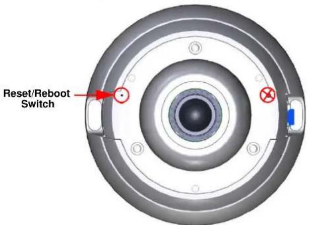
To access the reset switch the cover must be removed from the camera as seen in Figure 16-2 Removing the camera cover. Refer to the Quick Installation Guide supplied with the camera for details on how to remove the camera cover.
Figure 16-2 Removing the camera cover

Rebooting the Camera using the Reboot/Reset Switch
Perform a reboot of the camera using the reboot/reset switch.
Procedure 16-1 Reboot the camera using the Reboot/Reset Switch
Step Action
1 Locate the reset/reboot switch on the camera.
Refer to Figure 16-1 Reset/Reboot Switch.
2 Using the reset tool supplied with the camera, press and hold the reset/reboot switch for at least 5 seconds.
3 Release the reset switch.
4 When the camera is restarted it will take 2 - 3 minutes until it is online and ready to be accessed and controlled.
- End -
Resetting the Camera to Factory Default Settings using the Reset/Reboot Switch
The reset/reboot switch can be used to restore the camera to the factory default settings.
Note
It is not possible to retain network settings, presets, patterns or sequences when using this procedure. If you need to maintain these settings it is recommended to reset the camera using the Web User Interface. For more information, see Reset the Camera to Factory Default Settings.
Procedure 16-2 Reset the Camera to Factory Default Settings using the Reset/Reboot Switch
Step Action
1 Locate the reset/reboot switch on the camera.
Refer to Figure 16-1 Reset/Reboot Switch.
2 Using the reset tool supplied with the camera, press and hold the reset/reboot switch for 15 seconds or longer.
3 Release the reset switch.
When the camera is restarted it will take 2 - 3 minutes until it is online and ready to be accessed and controlled.
- End -
201113
Stream Combinations FW 1.00
| Stream 1 | Stream 2 | Stream 3 | Stream 4 | Stream 5 |
| Single Stream only | Single Stream only | Single Stream only | Single Stream only | Single Stream only |
| Fisheye | Fisheye | Not Available | Not Available | Not Available |
| Fisheye | Ceiling Panorama | Not Available | Not Available | Not Available |
| Fisheye | Wall Panorama | Not Available | Not Available | Not Available |
| Fisheye | Active Image X | Active Image X | Active Image X | Active Image X |
| Ceiling Panorama | Fisheye | Not Available | Not Available | Not Available |
| Ceiling Panorama | Ceiling Panorama | Not Available | Not Available | Not Available |
| Wall Panorama | Fisheye | Not Available | Not Available | Not Available |
| Wall Panorama | Wall Panorama | Not Available | Not Available | Not Available |
| Active Image X | Fisheye | Active Image X | Active Image X | Active Image X |
| Active Image X | Active Image X | Active Image X | Active Image X | Active Image X |
Stream Combinations – FW 1.03
| Stream 1 | Stream 2 | Stream 3 | Stream 4 | Stream 5 |
| Dual Stream (manual enabling required) | Dual Stream (manual enabling required) | Dual Stream (manual enabling required) | ||
| Fisheye | Ceiling Panorama | Not Available | Not Available | Not Available |
| Fisheye | Wall Panorama | Not Available | Not Available | Not Available |
| Fisheye | Active Image X | Active Image X | Not Available | Not Available |
| Ceiling Panorama | Fisheye | Not Available | Not Available | Not Available |
| Wall Panorama | Fisheye | Not Available | Not Available | Not Available |
Stream Combinations FW 3.00
| Stream 1 | Stream 2 | Stream 3 | Stream 4 | Stream 5 |
| Dual Stream | Dual Stream | Dual Stream | Dual Stream | Dual Stream |
| Fisheye | Fisheye | Not Available | Not Available | Not Available |
| Fisheye | Ceiling Panorama | Not Available | Not Available | Not Available |
| Fisheye | Wall Panorama | Not Available | Not Available | Not Available |
| Fisheye | Active Image X | Active Image X | Active Image X | Active Image X |
| Fisheye | Quad Image | Not Available | Not Available | Not Available |
| Ceiling Panorama | Fisheye | Not Available | Not Available | Not Available |
| Ceiling Panorama | Ceiling Panorama | Not Available | Not Available | Not Available |
| Wall Panorama | Fisheye | Not Available | Not Available | Not Available |
| Wall Panorama | Wall Panorama | Not Available | Not Available | Not Available |
| Active Image X | Fisheye | Active Image X | Active Image X | Active Image X |
| Active Image X | Active Image X | Active Image X | Active Image X | Active Image X |
| Quad Image | Quad Image | Not Available | Not Available | Not Available |
- ILLUSTRA
- CONFIGURATION AND USER
- GUIDE
- NOTICE
- COPYRIGHT
- CUSTOMER SERVICE
- TRADEMARKS
- LICENSE INFORMATION
- TABLE OF CONTENTS
- INTRODUCTION .... 1
- INSTALLATION 2
- WEBCONFIGURATION 6
- BASIC CONFIGURATION MENU....17
- VIDEO MENU 29
- PTZ MENU....51
- EVENTS MENU 63
- APPLICATIONS....76
- SECURITY....78
- NETWORK MENU....90
- MAINTENANCEMENU....99
- SUPPORT MENU....105
- EDGE RECORDING....112
- ABOUT MENU 116
- TECHNICALSPECIFICATIONS....118
- APPENDIX A: USER ACCOUNT ACCESS....128
- APPENDIX B: USING VLC PLAYER TO VIEW RTSP....132
- APPENDIX C: CAMERA DEFAULTS ....133
- APPENDIX D: PHYSICAL REBOOT/RESET OF THE CAMERA....136
- APPENDIX E: STREAM COMBINATIONS....138
- OVERVIEW
- CAMERA MOUNTS
- BROWSER SUPPORT
- NETWORK SETTINGS
- ILLUSTRA CONNECT
- KEY FUNCTIONS OF ILLUSTRA CONNECT ARE
- INSTALL AND DETECT THE ILLUSTRA PRO 5MP FISHEYE CAMERA
- INSTALLATION USING DHCP AND ILLUSTRA CONNECT
- NOTE
- PROCEDURE 2-1 INSTALLING THE ILLUSTRA PRO 5MP FISHEYE CAMERA USING ILLUSTRA CONNECT
- STEP ACTION
- END
- INSTALLING THE ILLUSTRA PRO 5MP FISHEYE CAMERA USING DHCP SERVER LOGS
- PROCEDURE 2-2 INSTALLING THE ILLUSTRA PRO 5MP FISHEYE CAMERA USING DHCP SERVER LOGS
- INSTALLATION WITHOUT A DHCP SERVER USING A STATIC IP ADDRESS
- PROCEDURE 2-3 INSTALLING THE ILLUSTRA PRO 5MP FISHEYE CAMERA WHEN A DHCP SERVER IS NOT AVAILABLE
- SECURITY MODE PROFILES FOR FIRST TIME CONNECTION
- ACCESSING THE ILLUSTRA PRO 5MP FISHEYE CAMERA WEB USER INTERFACE
- LOGGING IN TO THE CAMERA
- PROCEDURE 3-1 LOG IN TO THE CAMERA
- 7 SELECT LOG IN
- LOGGING OUT OF THE CAMERA
- PROCEDURE 3-2 LOG OFF THE CAMERA
- CHANGING THE CAMERA WEB USER INTERFACE LANGUAGE
- PROCEDURE 3-3 CHANGE THE CAMERA WEB USER INTERFACE LANGUAGE
- USER ACCOUNTS
- ADMINISTRATOR ACCESS
- OPERATOR ACCESS
- USER ACCESS
- THE CAMERA WEB USER INTERFACE
- ACCESSING THE SETUP MENUS FROM LIVE VIEW
- PROCEDURE 3-4 ACCESS SETUP MENUS FROM LIVE VIEW
- DISPLAYING THE LIVE VIEW PAGE
- OVERVIEW OF THE WEB USER INTERFACE
- WEB USER INTERFACE ICONS
- VIDEO PANE
- VIEWING LIVE STREAMS THROUGH THE VIDEO PANE
- PROCEDURE 3-6 VIEWING LIVE VIDEO THROUGH THE VIDEO PANE
- MAXIMIZE THE VIDEO PANE ON AN ACTIVE TAB
- PROCEDURE 3-7 MAXIMIZE OR MINIMIZE THE VIDEO PANE
- CONTROLLING THE PRO 5MP FISHEYE CAMERA USING PAN TILT ZOOM (PTZ)
- VPTZ CAMERA CONTROLS
- CONTROLLING THE CAMERA THROUGH CAMERA CONTROLS
- PROCEDURE 3-8 CONTROLLING THE CAMERA THROUGH THE VIDEO PANE
- CONTROLLING THE CAMERA USING KEYBOARD SHORTCUTS
- PROCEDURE 3-9 CONTROLLING THE CAMERA USING THE KEYBOARD SHORTCUTS
- BASIC CONFIGURATION MENU
- CAMERA
- MOUNTING
- PROCEDURE 4-1 SET MOUNTING POSITION FOR THE CAMERA
- CAMERA NAME
- PROCEDURE 4-2 EDIT THE CAMERA NAME
- USERS
- ADD USER
- PROCEDURE 4-3 ADD A USER
- CHANGING THE USER ACCOUNTS PASSWORD
- PROCEDURE 4-4 CHANGE USER PASSWORD
- VIEW CURRENT USER ACCOUNTS
- PROCEDURE 4-5 VIEW USER ACCOUNTS
- DELETE A USER ACCOUNT
- PROCEDURE 4-6 DELETE A USER ACCOUNT
- DATE TIME
- SETTING DATE TIME
- PROCEDURE 4-7 CONFIGURING THE DATE AND TIME
- TCP/IP
- IPV4
- DHCP
- IPV6
- STREAMS
- CONFIGURING THE WEB VIDEO STREAM
- WALL MODE
- CEILING MODE
- LT MODEL STREAMS
- PRO 5MP FISHEYE STREAMS
- DEFINING VIDEO STREAMS
- IMAGE SOURCE
- FISHEYE
- WALL PANORAMA
- CEILING PANORAMA
- ACTIVE IMAGE 1, 2, 3 AND 4
- QUAD VIEW
- PRO LT 5MP FISHEYE STREAMS
- ALARM VIDEO
- INTEGRATION WITH AMERICAN DYNAMICS NETWORK VIDEO RECORDERS
- INTEGRATION WITH OTHER ILLUSTRA API CLIENTS
- CONFIGURING THE VIDEO STREAM
- MOUNTING POSITION OF CAMERA
- PROCEDURE 5-2 SET MOUNTING POSITION FOR THE CAMERA
- PROCEDURE 5-3 EDIT THE CAMERA NAME
- PRIVACY ZONES
- DEFINING A PRIVACY ZONE
- PROCEDURE 5-4 DEFINE A PRIVACY ZONE
- ENABLING OR DISABLING A PRIVACY ZONE
- PROCEDURE 5-5 ENABLE/DISABLE A PRIVACY ZONE
- DELETING A PRIVACY ZONE
- PROCEDURE 5-6 DELETE A PRIVACY ZONE
- PICTURE SETTINGS
- WHITE BALANCE
- CONFIGURING WHITE BALANCE
- PROCEDURE 5-7 CONFIGURE AUTO WHITE BALANCE
- MANUALLY SELECT WHITE BALANCE
- PROCEDURE 5-8 MANUALLY SELECT WHITE BALANCE
- PICTURE BALANCE
- ADJUSTING PICTURE BALANCE
- PROCEDURE 5-9 ADJUST THE BRIGHTNESS, CONTRAST AND SATURATION
- RESTORING PICTURE BALANCE DEFAULTS
- PROCEDURE 5-10 RESTORE PICTURE BALANCE DEFAULTS
- WIDE DYNAMIC RANGE
- CONFIGURING WDR
- PROCEDURE 5-11 DISABLE/ENABLE WIDE DYNAMIC RANGE (WDR)
- PROCEDURE 5-12 CONFIGURE EXPOSURE SETTINGS
- SAVING PICTURE SETTINGS
- PROCEDURE 5-13 SAVE CURRENT PICTURE SETTINGS
- RESTORING SAVED PICTURE SETTINGS
- PROCEDURE 5-14 RESTORE SAVED PICTURE SETTINGS
- RESTORING FACTORY DEFAULT PICTURE SETTINGS
- PROCEDURE 5-15 RESTORE FACTORY PICTURE SETTINGS
- ON-SCREEN DISPLAY (OSD)
- DISPLAYING THE CAMERA NAME
- PROCEDURE 5-16 DISPLAY OR HIDE THE CAMERA NAME
- DISPLAYING THE CAMERA TIME
- PROCEDURE 5-17 DISPLAY OR HIDE THE CAMERA TIME
- PRESETS
- ADDING A NEW PRESET
- PROCEDURE 6-1 ADD A PRESET
- VIEWING A PRESET
- PROCEDURE 6-2 VIEW A PRESET
- EDITING A PRESET
- PROCEDURE 6-3 EDIT AN EXISTING PRESET
- DELETING A PRESET
- PROCEDURE 6-4 DELETE A PRESET
- SEQUENCES
- ADDING A SEQUENCE
- PROCEDURE 6-5 ADD A SEQUENCE
- ACTIVATING A SEQUENCE
- PROCEDURE 6-6 ACTIVATE A SEQUENCE
- EDITING A SEQUENCE
- PROCEDURE 6-7 EDIT A SEQUENCE
- DELETING A SEQUENCE
- PROCEDURE 6-8 DELETE A SEQUENCE
- PATTERNS
- ADDING A PATTERN
- PROCEDURE 6-9 ADD A PATTERN
- RUNNING A PATTERN
- PROCEDURE 6-10 RUN A PATTERN
- DELETING A PATTERN
- PROCEDURE 6-11 DELETE A PATTERN
- REPEATING A PATTERN
- PROCEDURE 6-12 ENABLE/DISABLE REPEAT A PATTERN
- SCANS
- SETTING SCAN LIMITS
- PROCEDURE 6-13 SET SCAN LIMITS
- SET SCAN LIMITS TO DEFAULT SETTINGS
- PROCEDURE 6-14 SET SCAN LIMITS TO DEFAULT SETTINGS
- ACTIVATING A SCAN
- PROCEDURE 6-15 ACTIVATE A SCAN
- FAULT SETTINGS
- SMTP
- CONFIGURE SMTP
- PROCEDURE 7-2 CONFIGURE SMTP SETTINGS
- TEST SMTP SETTINGS
- PROCEDURE 7-3 TEST THE SMTP SETTINGS
- FTP
- CONFIGURING FTP SERVER SETTINGS
- PROCEDURE 7-4 CONFIGURE FTP SERVER SETTINGS
- TEST FTP SETTINGS
- PROCEDURE 7-5 TEST THE FTP SETTINGS
- CIFS
- PROCEDURE 7-4 CONFIGURE CIFS SERVER SETTINGS
- FAULT ACTIONS
- CREATING A FAULT ACTION
- PROCEDURE 7-6 CREATE A FAULT ACTION
- EDITING A FAULT ACTION
- PROCEDURE 7-7 EDIT AN ALARM
- MOTION DETECTION
- MOTION DETECTION BEST PRACTICES
- MOTION DETECTION CONFIGURATION PANE
- CREATING A MOTION DETECTION ALERT
- PROCEDURE 7-8 CREATE A MOTION DETECTION ALERT
- ENABLE OR DISABLE A MOTION DETECTION ALERT
- PROCEDURE 7-9 ENABLE OR DISABLE A MOTION DETECTION ALERT
- SCHEDULED TASKS
- CREATING A SCHEDULED TASK
- PROCEDURE 7-10 CREATE A SCHEDULED TASK
- EDITING A SCHEDULED TASK
- PROCEDURE 7-11 EDIT A SCHEDULED TASK
- DELETING A SCHEDULED TASK
- PROCEDURE 7-12 DELETE A SCHEDULED TASK
- APPLICATIONS
- PROCEDURE 8-1 UPLOAD AN APPLICATION
- AVAILABLE APPLICATIONS
- PROCEDURE 8-2 START, STOP, OR REMOVE AN APPLICATION
- LICENSE
- PROCEDURE 8-3 UPLOAD A LICENSE FILE
- SECURITY STATUS
- ENHANCED SECURITY
- PROCEDURE 9-1 ENABLE ENHANCED SECURITY
- SETTING COMMUNICATION PROTOCOLS
- PROCEDURE 9-4 ADD A USER
- PROCEDURE 9-5 CHANGE USER PASSWORD
- PROCEDURE 9-6 VIEW USER ACCOUNTS
- PROCEDURE 9-7 DELETE A USER ACCOUNT
- HTTP/HTTPS
- UPLOAD A HTTP/HTTPS CERTIFICATE
- PROCEDURE 9-8 ADD A HTTP/HTTPS CERTIFICATE
- DELETE A CERTIFICATE
- PROCEDURE 9-9 DELETE A HTTP/HTTPS CERTIFICATE
- IEEE 802.1X
- PROCEDURE 9-10 CONFIGURE IEEE 802.1X SECURITY
- FIREWALL
- BASIC FILTERING
- PROCEDURE 9-11 ENABLE/DISABLE BASIC FILTERING
- ADDRESS FILTERING
- PROCEDURE 9-12 ENABLE/DISABLE AND CONFIGURE ADDRESS FILTERING
- EDITING AN ADDRESS FILTER
- PROCEDURE 9-13 EDIT AN ADDRESS FILTER
- DELETING AN ADDRESS FILTER
- PROCEDURE 9-14 DELETE AN ADDRESS FILTER
- REMOTE ACCESS
- SSH ENABLE
- PROCEDURE 9-15 CONFIGURE SSH
- ONVIF
- ONVIF DISCOVERY MODE
- PROCEDURE 9-16 ENABLE/DISABLE ONVIF DISCOVERY MODE
- ONVIF USER AUTHENTICATION
- PROCEDURE 9-17 ENABLE/DISABLE ONVIF USER AUTHENTICATION
- SESSION TIMEOUT
- PROCEDURE 9-18 SET A SESSION TIMEOUT TIME
- PROCEDURE 10-1 CONFIGURING THE DATE AND TIME
- PROCEDURE 10-2 CONFIGURE THE IPV4 SETTINGS
- PROCEDURE 10-3 ENABLE/DISABLE IPV6
- PROCEDURE 10-4 ENABLE DHCP
- PROCEDURE 10-5 DISABLE DHCP
- PROCEDURE 10-6 CONFIGURE SMTP SETTINGS
- PROCEDURE 10-7 TEST THE SMTP SETTINGS
- PROCEDURE 10-8 CONFIGURE FTP SERVER SETTINGS
- PROCEDURE 10-9 TEST THE FTP SETTINGS
- DYNAMIC DNS
- PROCEDURE 10-10 CONFIGURE DYNAMIC DNS
- 4 IF SERVICE ENABLE HAS BEEN ENABLED
- BACKUP/RESTORE
- SAVE CAMERA DATA
- PROCEDURE 11-1 BACKUP CAMERA DATA
- RESTORE CAMERA DATA
- CAMERA UPGRADE
- UPGRADE CAMERA FIRMWARE
- CAUTION
- PROCEDURE 11-3 UPGRADE CAMERA FIRMWARE
- REBOOT
- REBOOTING THE CAMERA
- PROCEDURE 11-4 REBOOT THE CAMERA
- RESET
- RESET THE CAMERA TO FACTORY DEFAULT SETTINGS
- PROCEDURE 11-5 RESETTING THE CAMERA
- CURRENT FAULTS
- DETAILS THE FAULT INDEX
- FAULT DETAILS
- SYSTEM FAULTS
- ENVM (ENVIRONMENTAL MONITOR) COMPONENT
- PROCEDURE 12-1 DISPLAY CURRENT FAULTS
- PROCEDURE 12-2 DELETE CURRENT FAULTS
- CURRENT EVENTS
- DETAILS THE EVENT INDEX
- PROCEDURE 12-3 DISPLAY CURRENT EVENTS
- PROCEDURE 12-4 DELETE CURRENT EVENTS
- LOGS
- SYSTEM LOG
- PROCEDURE 12-5 DISPLAY SYSTEM LOG
- PROCEDURE 12-6 SYSTEM LOG FILTER
- BOOT LOG
- PROCEDURE 12-7 DISPLAY BOOT LOG
- PROCEDURE 12-8 BOOT LOG FILTER
- ENVIRONMENTAL
- ENVIRONMENTAL INFORMATION
- PROCEDURE 12-9 DISPLAY GENERAL INFORMATION
- STATISTICS
- PROCEDURE 12-10 DISPLAY GENERAL INFORMATION
- SD CARD MANAGEMENT
- INSERTING THE SD CARD
- PROCEDURE 13-1 INSERT THE SD CARD BY POWERING DOWN THE CAMERA
- PROCEDURE 13-2 MOUNT THE SD CARD USING THE WEB USER INTERFACE TO REBOOT THE CAMERA
- REMOVING THE MICROSD CARD
- PROCEDURE 13-3 REMOVE THE MICROSD CARD BY POWERING DOWN THE CAMERA
- PROCEDURE 13-4 UNMOUNT THE MICROSD CARD FOR REMOVAL
- RECORD SETTINGS
- PROCEDURE 13-5 CONFIGURE RECORD SETTINGS
- 5 SELECT APPLY TO SAVE
- EVENT DOWNLOAD
- MODEL
- MODEL INFORMATION
- PROCEDURE 14-1 DISPLAY MODEL INFORMATION
- VIDEO COMPRESSION
- MJPEG/JPEG COMPRESSOR KEY FUNCTIONALITY
- H.264 COMPRESSOR KEY FUNCTIONALITY
- NETWORK
- BASE PROTOCOL AND UNDERLYING LAYERS
- NETWORK ADDRESS CONFIGURATION
- NETWORK NAME RESOLUTION
- TIME SYNCHRONIZATION AND CONFIGURATION
- REMOTE SHELL ACCESS
- AUTHENTICATION AND SECURITY
- DISCOVERY
- ONVIF VIDEO AND CONTROL INTERFACE
- ONVIF FUNCTIONS SUPPORTED
- DEVICE MANAGEMENT
- SYSTEM MANAGEMENT
- SECURITY
- CONFIGURE VIDEO AND AUDIO
- EVENT HANDLING BASIC NOTIFICATION INTERFACE
- ONVIF EXTENSIONS SUPPORTED
- ONVIF FUNCTIONS NOT SUPPORTED
- MICROSD CARD
- DIMENSIONS
- WEIGHT
- POWER
- SURGE PROTECTION
- REGULATORY COMPLIANCE
- APPENDIX B: USING VLC PLAYER TO VIEW RTSP STREAMING
- VIEWING RTSP STREAM VIA VLC PLAYER
- PROCEDURE 15-1 VIEW RTSP STREAMING VIA VLC PLAYER
- APPENDIX D: PHYSICAL REBOOT/RESET OF THECAMERA
- REBOOTING THE CAMERA USING THE REBOOT/RESET SWITCH
- PROCEDURE 16-1 REBOOT THE CAMERA USING THE REBOOT/RESET SWITCH
- RESETTING THE CAMERA TO FACTORY DEFAULT SETTINGS USING THE RESET/REBOOT SWITCH
- PROCEDURE 16-2 RESET THE CAMERA TO FACTORY DEFAULT SETTINGS USING THE RESET/REBOOT SWITCH
Brand : Illustra
Model : ADCI825LT-F311
Category : Security Camera